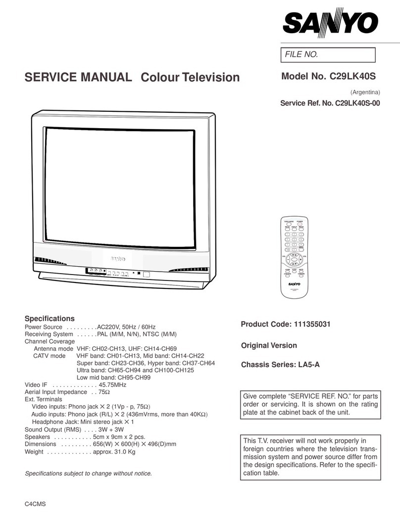
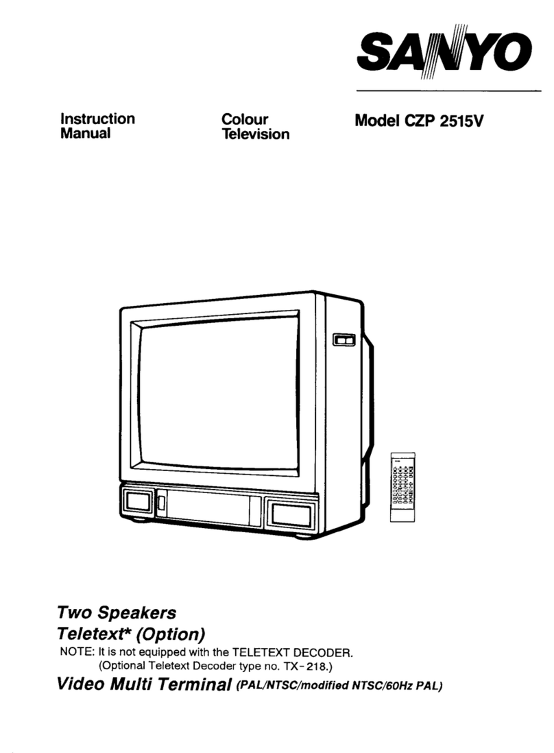
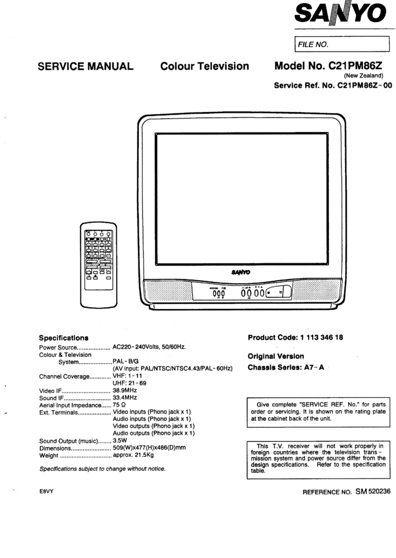
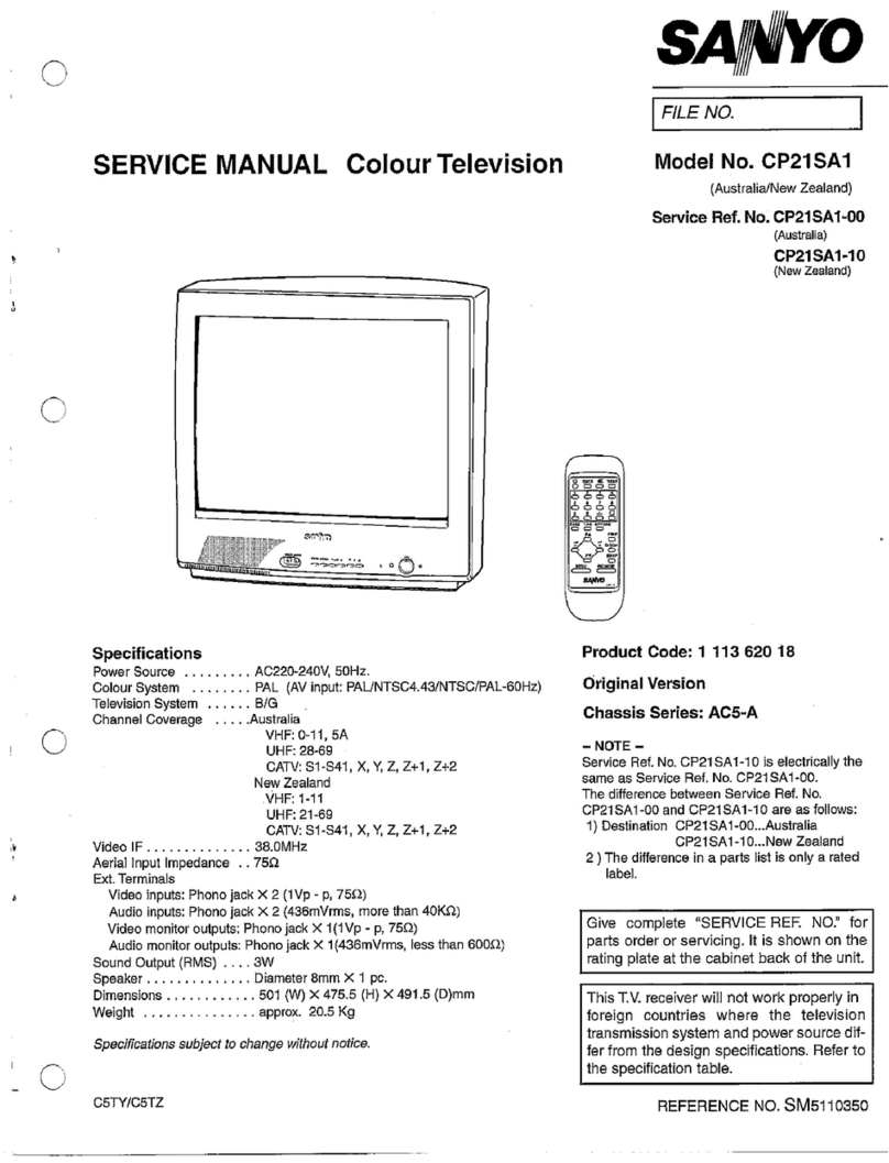
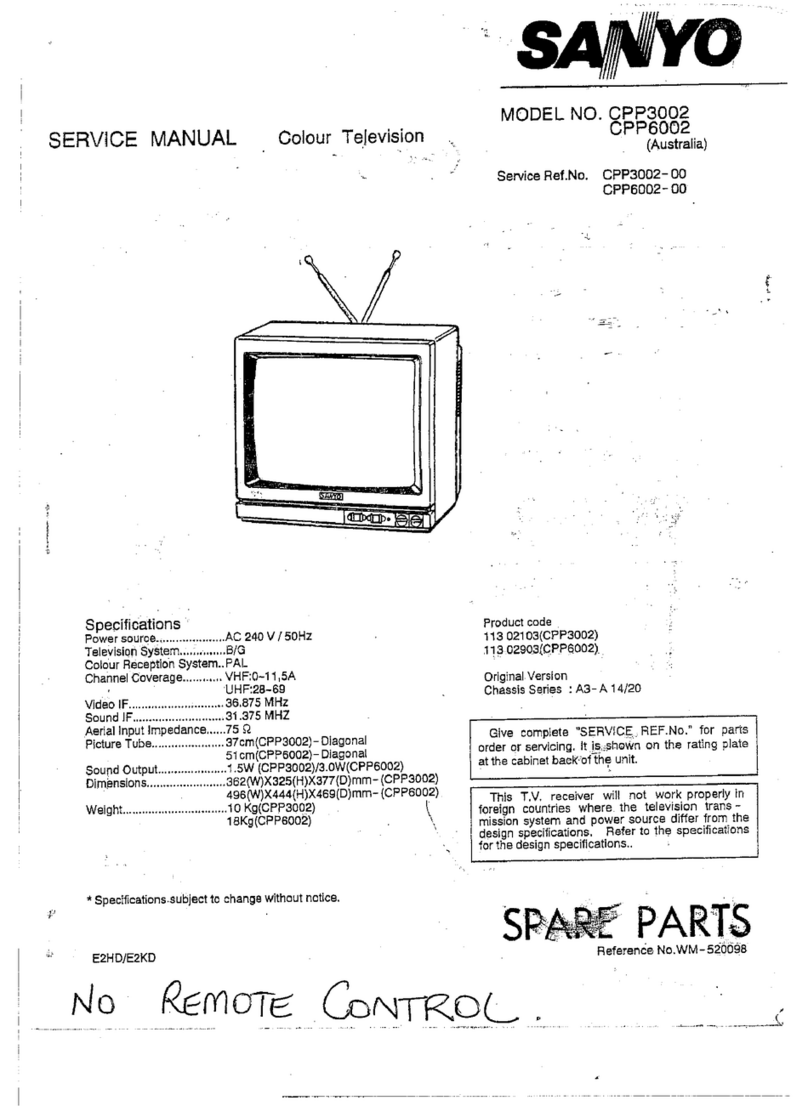
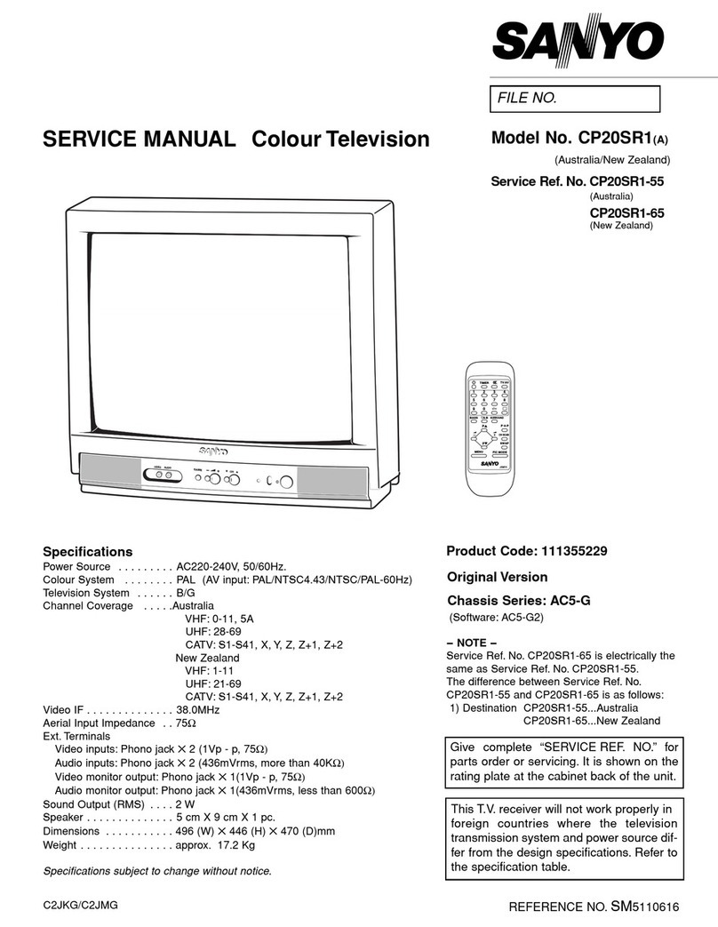
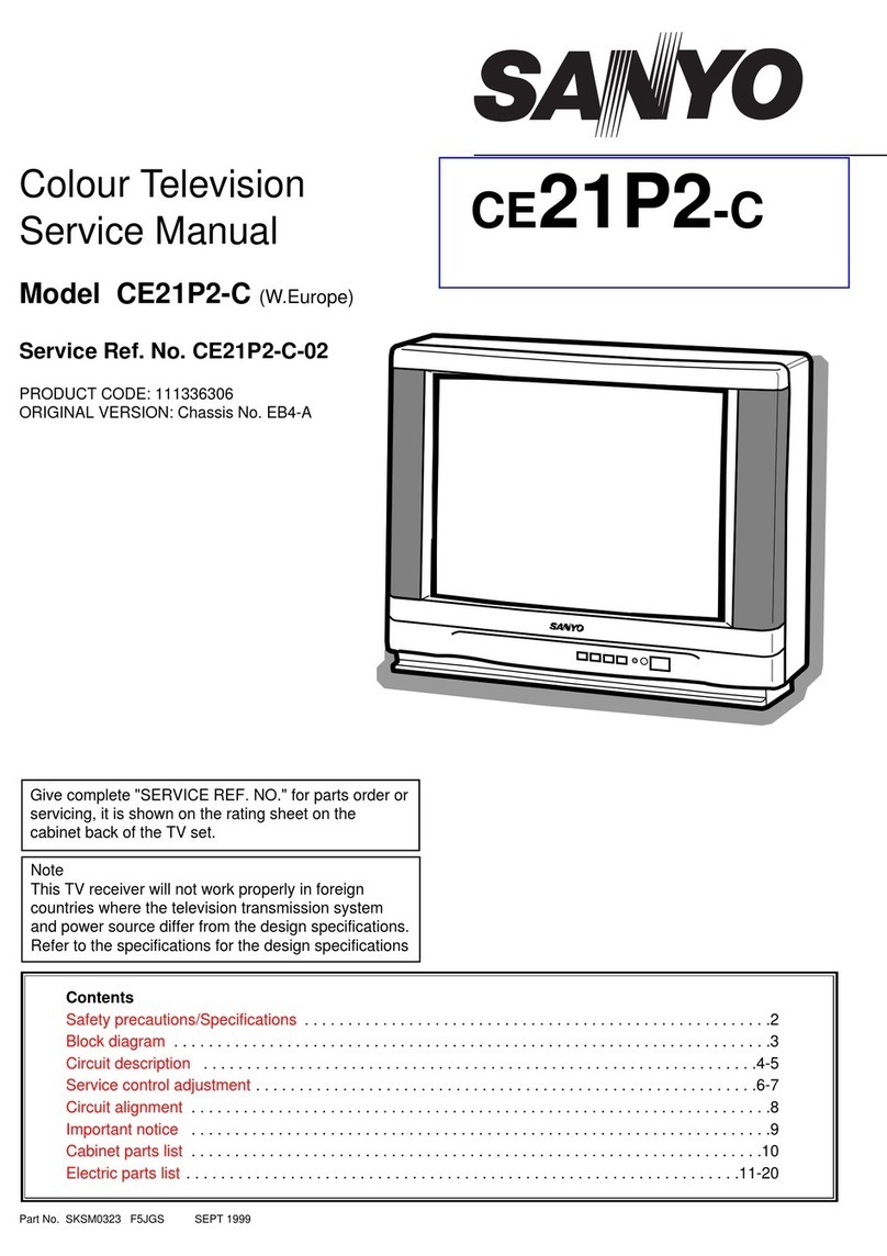
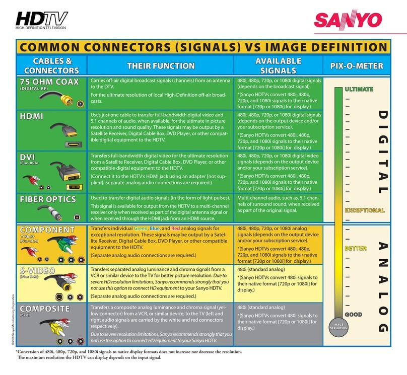
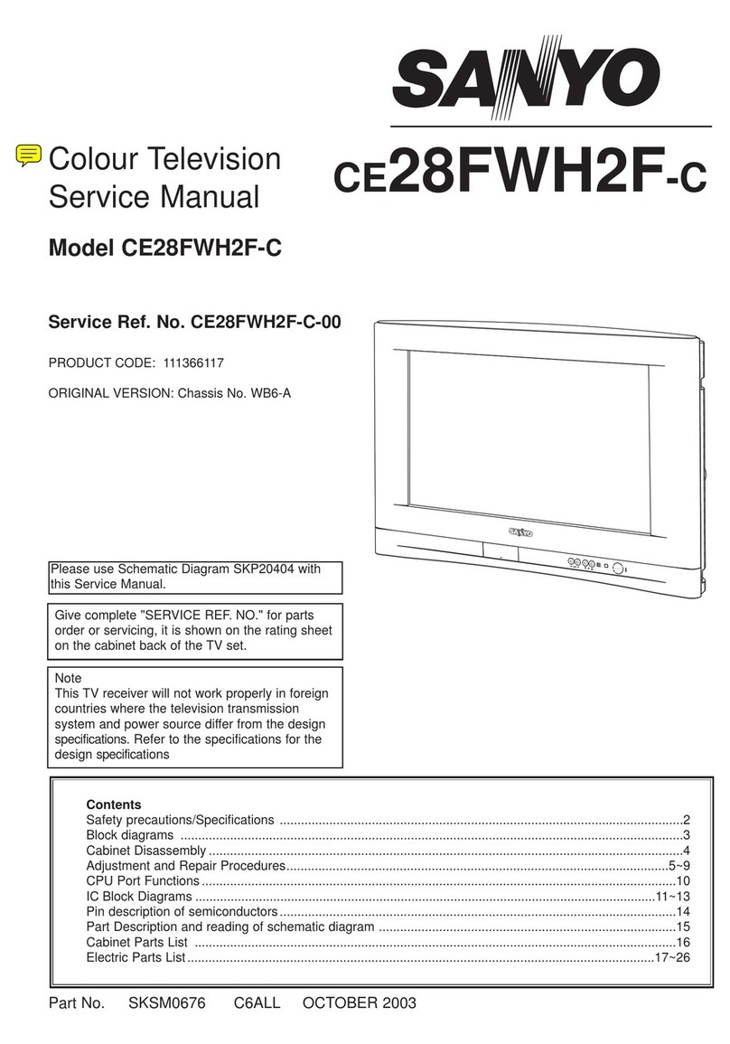
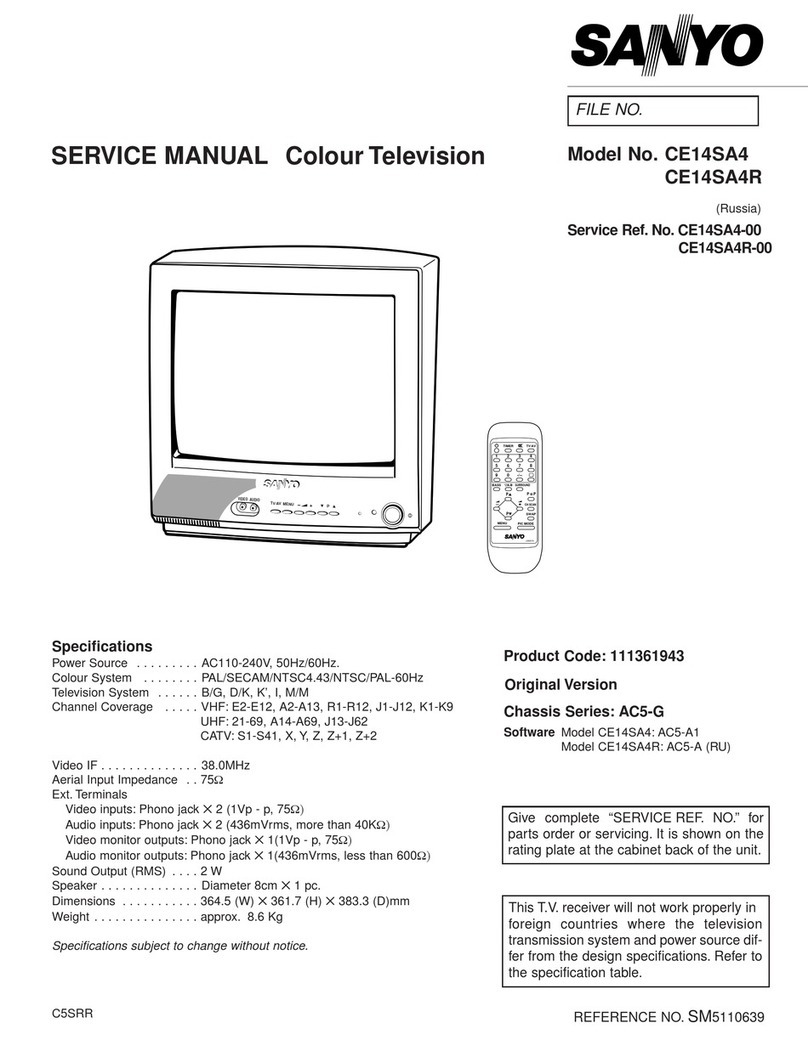
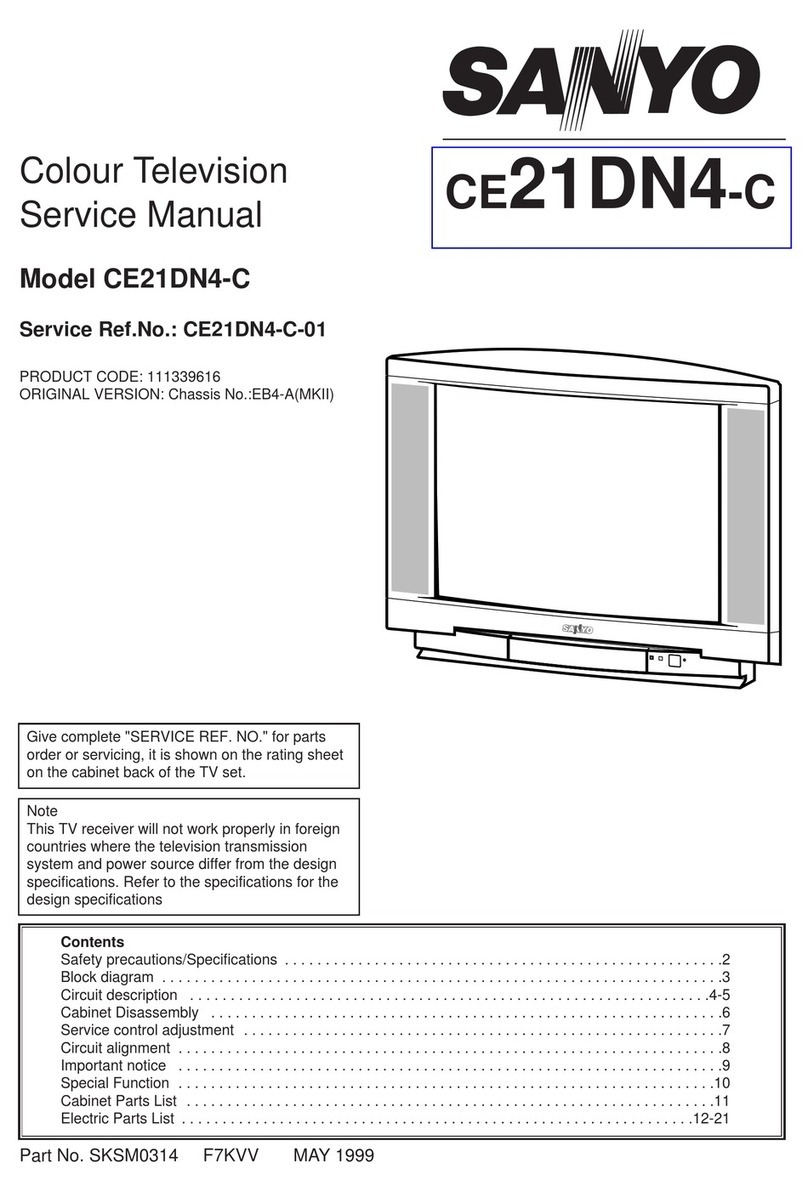
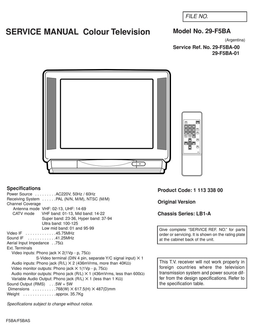
Sanyo C21ES35 User manual

Part No. SKSM0178 F2TEV APRIL 1997
Colour Television
Service Manual
Give complete "SERVICE REF. NO." for parts
order or servicing, it is shown on the rating sheet
on the cabinet back of the TV set.
Note
This TV receiver will not work properly in foreign
countries where the television transmission sys-
tem and power source differ from the design
specifications. Refer to the specifications for the
design specifications
Model: C21ES35 (W.EUROPE)
Ser Ref No. C21ES35-01
Product Code: 1113 34004
Chassis: EC5-A
Original Manual
21MT2
Power Source AC220~240V 50Hz
Television System System BG
Colour System PAL
Receiving Channels VHF : E2~E12
CATV : X,Y,Z,S1~S41
UHF : 21~69
Aerial input impedance 75ohm
AV Terminal 21 pin SCART (AV1)
Speaker 8ohm, 8 x 8 cm
Sound output 2W (cont.)
Picture tube 55 cm diagonal, 90˙
Visible picture 51 cm (diagonal)
Dimensions (W x H xD) 521 x 465 x 481 mm
Weight 21 kg
Page
Safety precautions ..............................2
Block diagram
Main signal routing ..........................3
Power signal routing ........................4
Circuit description .............................5~6
Service control adjustments..............7~8
Circuit alignment.................................9
Memory IC replacement ....................10
Special functions................................11
Cabinet parts list................................12
Chassis electricl parts list...............13~19
Schematic Diagram .........................loose
SPECIFICATIONS CONTENTS

-2- Service manual-EC5 chassis
SAFETY PRECAUTION
X-RADIATION PRECAUTION
The primary source of X-RADIATION in the television receiver is the picture tube.The picture tube is specially con-
structed to limit X-RADIATION emissions. For continued X-RADIATION protection, the replacement tube must be
the same type as the original including suffix letter. Excessive high voltage may produce potentially hazardous X-
RADIATION. To avoid such hazards, the high voltage must be maintained within specified limit. Refer to this ser-
vice manual, high voltage adjustment for specific high voltage limit. If high voltage exceeds specified limits, take
necessary corrective action. Carefully follow the instructions for +B1 volt power supply adjustment, and high volt-
age adjustment to maintain the high voltage within the specified limits.
PRODUCT SAFETY NOTICE
Product safety should be considered when a component replacement is made in any area of a receiver.
Components indicated by mark //!\ in the parts list and the schematic diagram designate components in which safe-
ty can be of special significance. It is particularly recommended that only parts designated on the parts list in this
manual be used for component replacement designated by mark /!\ . No deviations from resistance wattage or
voltage ratings may be made for replacement items designated by mark /!\ .
1: An isolation transformer should be connected in the
power line between the receiver and the AC line when
a service is performed on the primary of the converter
transformer of the set.
2: Comply with all caution and safety-related notes pro-
vided on the cabinet back, inside the cabinet, on the
chassis or the picture tube.
3:When replacing a chassis in the cabinet, always be cer-
tain that all the protective devices are installed proper-
ly, such as, control knobs, adjustment covers or
shields, barriers, isolation resistor-capacitor networks
etc.Before returning any television to the customer, the
service technician must be sure that it is completely
safe to operate without danger of electrical shock.

-3-
Service manual-EC5 chassis
BLOCK DIAGRAM (Main signal routing)
This is a diagram for all models and therefore differs slightly from the actual block diagram.
+130V
+24V
+18V
+15V
TU
VL
VH
U
IF
Q801
Q101/Q102
Q103/Q104
Q105/Q106
Tuner
Key scan
10 Scan
1 Tu
51 VL
52 VH
3 U
8 Standby
SCL 49
SDA 50
BLK 35
R 34
G 33
B 32
Sharp 3
Bright 6
Cont 5
Colour 4
TV/AV 14
6 SCL
5 SDA
46
45
22 R
23 G
24 B
21 BLK
14 Sharp
17 Bright
25 Cont
26 Colour
Volume 7
13 TV/AV
30 R-Y
31 B-Y
29 R-Y
28 B-Y
30 R-Y
31 B-Y
29 R-Y
28 B-Y 50 Sound
R out 18
G out 19
B out 20
CVBS out 7
SIF in 5
Int.video 13
Ext.video 15
Ext.audio 6
Audio out 1
H out
37 41 43
V-F/B
V out
42
42
8
R-out Q711
G-out Q721
B-out Q701
IC501 V-out
H-out circuit
Q431 Q432
V-control
circuit Deflection
Yoke
T471 Flyback Trans.
High Voltage
Q151 X151
X161 Q161 Q154
Q241 SCART
19
20
2, 6
1, 3
Video out
Video in
Audio in
Audio out
Q1032/Q1031
IC801 CPU IC201
IF/video/chroma/def.
IC802 Memory X131
SAW
IC271
1H delay
IC001
Audio out
Power
control
circuit
T611
converter trans.
AC
in
Q839
Power supply circuit
CRT Unit

-4- Service manual-EC5 chassis
(Power supply routing)
D634
+15V
+5V
+18V
+24V
+130V
13
13
IC691
IC661
Q661
Q651
+9V
+8V
control
circuit
Q611,
Q612
Power
switching
Q613
C607
D601~D604
T611
converter trans.
AC in
IC801
CPU
IC802
Memory
A1901
RC Pre-amp
A101
Tuner
IC271
1H delay
IC001
Audio out
Speaker
CRT Unit
T471
FBT
Horizontal
Drive circuit
IC501
V-out
IC201
IF/video/chroma/def.
44 8
3
MB
10
36 9
19
8
62
2
V.deflection
+5V
+9V
+5V
+8V
+8V
+18V
+9V
+130V/
+150V
+130V/
+150V
+24V
+24V
Power supply circuit
Standby signal from CPU pin 8
+150V

-5-
Service manual-EC5 chassis
1. POWER SUPPLY
The power supply circuit of the EC5-A chassis is com-
posed of a rectifier smoothing circuit, an oscillation circuit,
a control circuit and an output rectifier circuit. The AC
input voltage is full-wave rectified by the rectifier smooth-
ing circuit, and an unstable DC voltage is generated at
both terminals of the smoothing capacitor C607.This volt-
age is input to the oscillation circuit.The oscillation circuit
is provided with a blocking oscillator circuit that switches
the switching transistor Q613 ON and OFF, and an oscil-
lation frequency and a duty square wave pulse are gener-
ated in the input windings according to operation of the
control circuit. A square-wave pulse whose size is depen-
dent on the turn ratio of the input and output windings is
obtained in the output winding.This is rectified in the out-
put rectifier circuit, and the desired DC voltage is
obtained.
2. IF & DEFLECTION (TDA8361)
The IF output signal from the tuner passes through the
SAW filter, and it is input to pin45 and pin46 of IC201.The
signal input to the IC passes through the IF amplifier,
video detection and video amplifier circuits and is output
from pin7 as a composite video signal. And after this sig-
nal is converted to impedance at Q151, supplies to the
video and chroma amplifier stages.
The sync.-separation circuit separates the video signals
applied to pin13(internal video signal) or pin15(external
video signal) to vertical- and horizontal-sync. signals
respectively.The horizontal oscillator requires no external
components and is fully integrated. The oscillator is
always running when the start-pin36 is supplied with 8V.
Horizontal drive signal is output from pin37. VR361 is for
adjustment of the horizontal centring. The separated ver-
tical-sync. signal from sync. separation circuit passes
through the vertical-separation circuit, and applied to trig-
ger divider circuit. The horizontal oscillation pulse and
input vertical sync. pulse are monitored by the trigger
divider circuit, and switching 50Hz and 60Hz system, the
vertical amplitude automatically adjusted for 50Hz and
60Hz. The output signal from the trigger divider is trig-
gered vertical oscillation circuit consisting of C351, R356
and pin42, and vertical drive pulse is output from pin43.
VR501 is for changing the amount of AC feedback applied
to pin41 and for adjustment of the vertical amplitude.
3.VIDEO CHROMA & R.G.B. (TDA8361)
The composite video signal output from the pin7 of IC201
passes through Q151-Q154, and it is supplied to pin13.
The external video signal output from SCART is supplied
to pin15.The video signal input to pin13 or pin15 is sepa-
rated to luminance (Y) signal and chroma signal in IC201.
These pins are used in common with H/V-sync.separation
input.The peaking ofY signal is adjusted by DC voltage of
pin14. (“SHARPNESS” control) The chroma signal is
divided into R-Y and B-Y chroma signals, demodulated in
IC201, and output from pin30 (R-Y) and pin31 (B-Y).
These chroma signals pass through the 1H delay line cir-
cuit (IC271), and they are input to pin29 (R-Y) and pin28
(B-Y). These R-Y/B-Y signals pass through RGB matrix
circuit and RGB selector circuit of IC201. The internal
RGB signals are generated in RGB matrix circuit and the
RGB selector, consisting linear amplifiers, clamps and
selects either the internal RGB signals or the external
RGB signals input from pin22(R), pin23(G), pin24(B).
Selection is controlled by the voltage at the RGB switch
control (pin21) and mixed RGB modes are possible since
RGB switching is fast. The RGB switch also functions as
a fast blanking pin by blanking the RGB output stages;
here internal and external RGB signals are overruled.The
colour gain is controlled by DC voltage of pin26.
(“COLOUR” control) The contrast control voltage present
at pin25, and the brightness control voltage present at
pin17 controls DC level of RGB signals.The RGB signals
are finally buffered before being available at the RGB out-
put pins [pin20 (R), pin19 (G), pin18 (R)].
4. AUDIO OUTPUT(AN5265)
The audio signal output from pin52 of IC201 is input to
pin2 of IC001 and passes through the pre-amplifier circuit
and drive circuit, after which it is input to the audio ampli-
fier. The audio amplifier is an SEPP (single-ended, push-
pull) OTL type and output to pin8 to directly drive the
speaker.
5.VERTICAL OUTPUT (LA7832/LA7833)
An IC (LA7832/LA7833) is used for the vertical output cir-
cuit in this chassis.The vertical drive pulse from pin43 of
IC201 is input to pin4 of IC501. This pulse drives IC501,
and vertical scanning is performed. In the first half of
scanning a deflecting current is output from pin2 and
passes through the following path:
Vcc(B4) ➞D501 ➞pin3 ➞pin2 ➞DY ➞C512 ➞
VR501/R509.An electric charge is then stored in C512.In
the last half of scanning the current path is C512 ➞DY ➞
pin2 ➞pin1 ➞ VR501/R509 ➞C512. In this way, an
amplifying sawtooth waveform current flows directly to DY
to perform electron beam defection. Next, in the first half
of the banking period the vertical drive pulse suddenly
becomes OFF, and in order to reduce the current flowing
to DY, the current path becomes as follows by the induc-
tance of DY:
DY ➞pin2 ➞pin1 ➞VR501/R509 ➞C512 ➞DY. Also,
when the charge of DY has dissipated, the current path
becomes Vcc24V ➞pin6 ➞pin7 ➞ C502 ➞pin3 ➞
pin2➞DY ➞C512 ➞ VR501/R509, and when the pre-
scribed current value is reached, the vertical drive pulse
becomes ON.This completes one cycle.
6. HORIZONTAL OUTPUT
A horizontal oscillation signal is output from pin37 of
IC201 and switches the drive transistor Q431.This switch-
CIRCUIT DESCRIPTION
This manual suits for next models
3
Table of contents
Other Sanyo TV manuals

Sanyo
Sanyo CE25D6-C User manual

Sanyo
Sanyo DS27820 User manual

Sanyo
Sanyo CE25DN7-C User manual

Sanyo
Sanyo LCD-50XR12F User manual

Sanyo
Sanyo DS25520 User manual

Sanyo
Sanyo C25PP81S User manual

Sanyo
Sanyo CP28WF1 User manual

Sanyo
Sanyo CE42FD17-B User manual

Sanyo
Sanyo LCD-47XR8DA User manual

Sanyo
Sanyo CP20SW1Z User manual

Sanyo
Sanyo C25PG41 User manual

Sanyo
Sanyo C29AK86 User manual

Sanyo
Sanyo DP37649 User manual

Sanyo
Sanyo CZP2510 User manual

Sanyo
Sanyo CP21AF2T User manual

Sanyo
Sanyo CPP2930TX User manual

Sanyo
Sanyo CP28WF1 User manual

Sanyo
Sanyo AVM-2058G User manual

Sanyo
Sanyo CZP 6011V User manual

Sanyo
Sanyo CZP1662 User manual