Sanyo CP29AF2 User manual

SERVICE MANUAL Colour Television
-
+
P
MENU
TV/AV
Specifications
Power Source . . . . . . . . .AC220
-
240V, 50/60Hz.
Colour System . . . . . . . .PAL (AV input : PAL/NTSC4.43/NTSC/PAL-60Hz)
Television System . . . . . .B/G
Channel Coverage . . . . .Australian Channels
VHF: 0-11, 5A
UHF: 28-69
CATV: S1-S41, X, Y, Z, Z+1, Z+2
New Zealand Channels
VHF: 1-11
UHF: 21-69
CATV: S1-S41, X, Y, Z, Z+1, Z+2
Video IF . . . . . . . . . . . . . 38.0MHz
Aerial Input Impedance . . 75Ω
Ext. Terminals
Video inputs: Phono jack ✕3 (1.0Vp
-
p, impedance 75Ω)
S-Video input ✕1 (Din 4 pin, Separate Y/C Signals Input)
Audio inputs:Phono jack (R/L) ✕ 3 (436mVrms, impedance more than 40KΩ)
Video monitor outputs: Phono jack ✕1 (1.0Vp
-
p, 75Ω)
Audio monitor outputs: Phono jack(R/L) ✕1
(436mVrms, Impedance less than 600Ω)
Headphone jack: Mini stereo jack ✕ 1
Speakers ......... 6cm ✕12cm ✕ 2
Sound Output (Music) . . . 7.5W + 7.5W
Dimensions . . . . . . . . . . 750(W) ✕583(H) ✕503(D)mm
Weight . . . . . . . . . . . . . .approx. 46.8 Kg
Specifications subject to change without notice
Product Code: 1 113 516 18
Chassis Series: FA1
C2SY
FILE NO.
Model No. CP29AF2
Service Ref. No. CP29AF2-00
(Australia)
Give complete “SERVICE REF. NO.” for parts
order or servicing. It is shown on the rating plate
at the cabinet back of the unit.
This T.V. receiver will not work properly in
foreign countries where the television
transmission system and power source dif-
fer from the design specifications. Refer to
the specification table.
0
7
14
8
5
23
6
9
JXMLF
MENU
-/--
PP
A•B
CH SCAN
TIMER TV/AV
P
▲
P
▼
SWAPVSM
BBE BASS
ASM
SURROUND
REFERENCE NO. SM5110330
Original Version

Contents
-2-
Safety Notice . . . . . . . . . . . . . . . . . . . . . . . . . . . . . . . . . . . . . . . . . . . . . 2
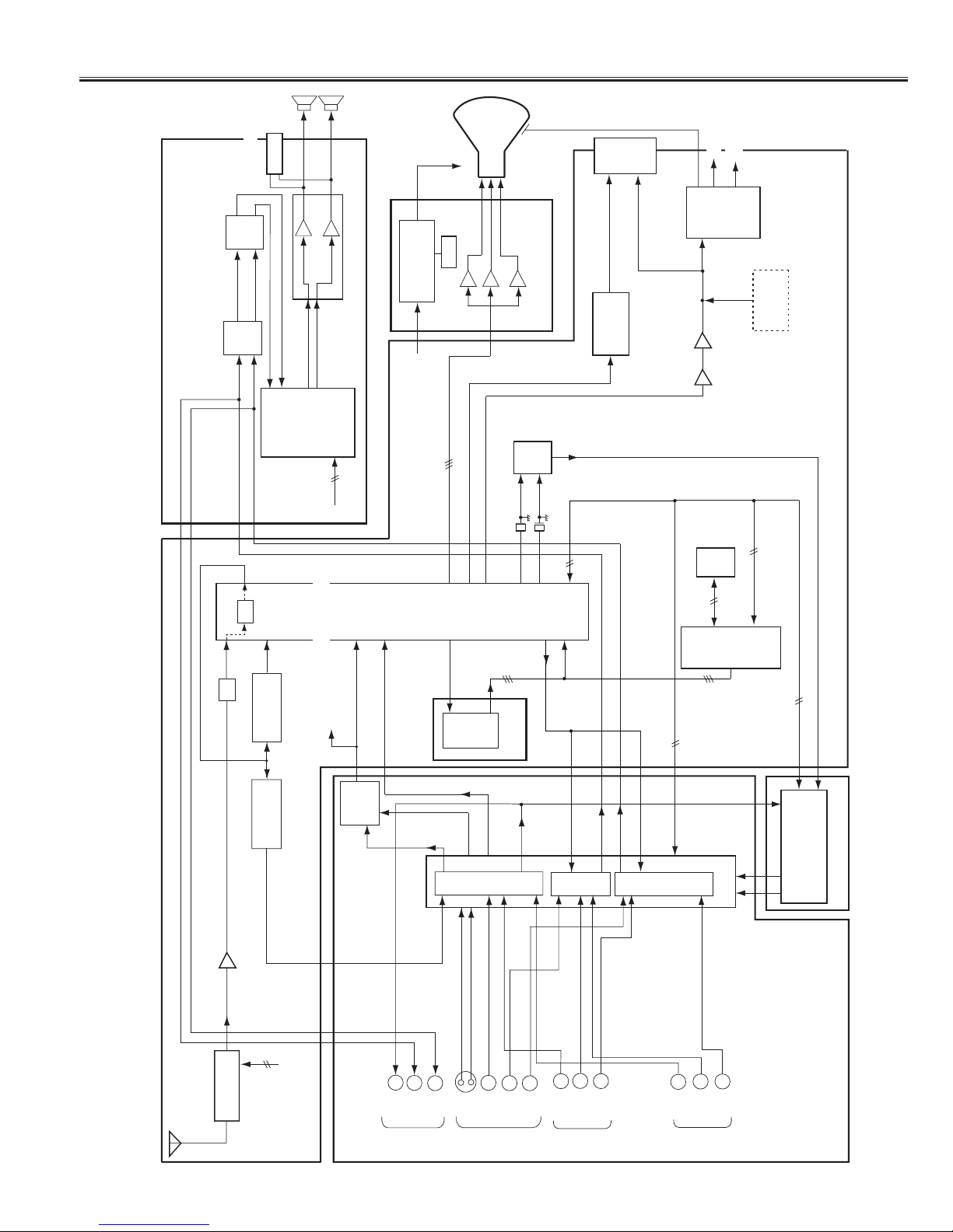
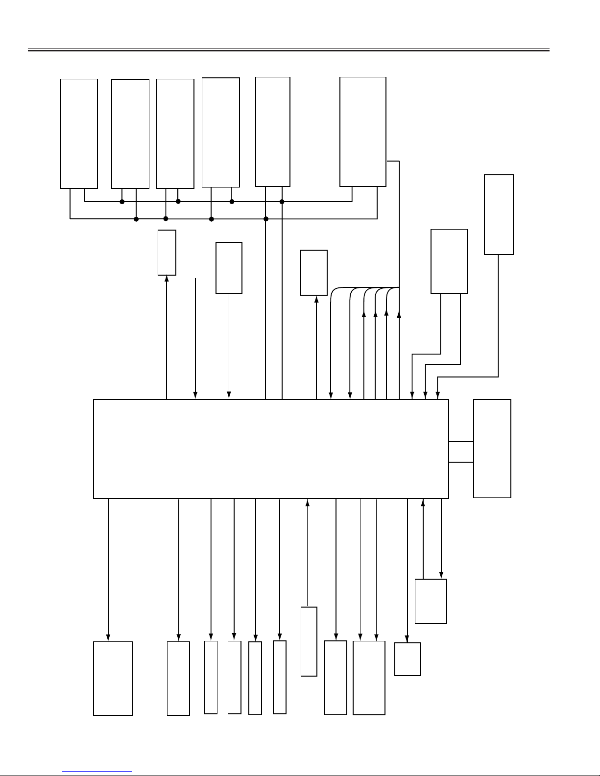
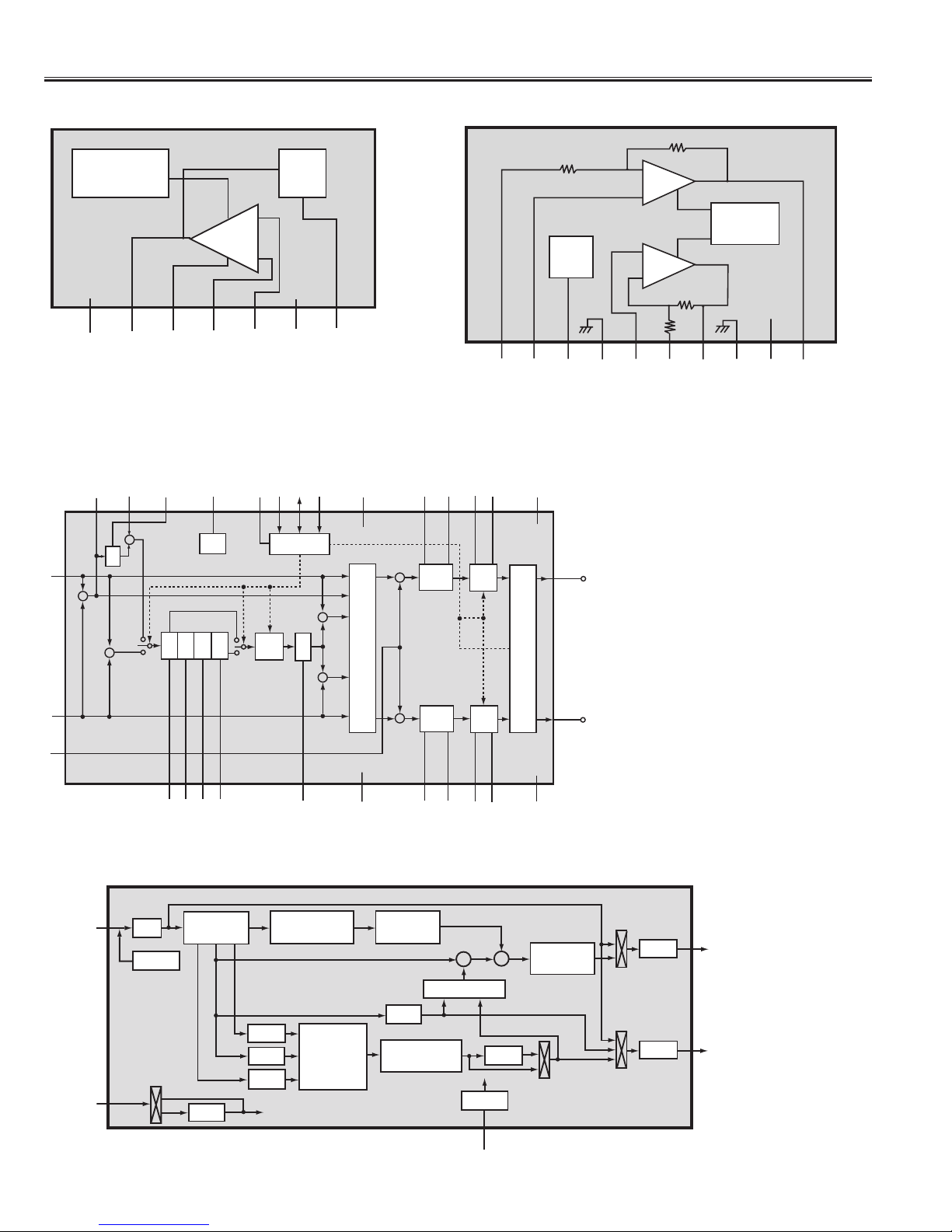
Chassis Block Diagram . . . . . . . . . . . . . . . . . . . . . . . . . . . . . . . . . . . . 3-4
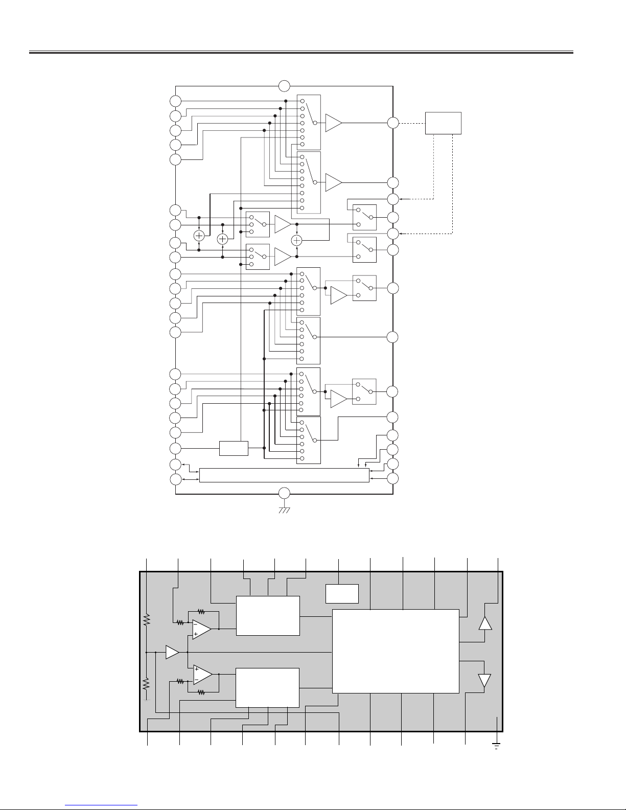
IC Block Diagrams . . . . . . . . . . . . . . . . . . . . . . . . . . . . . . . . . . . . . . . 5-8
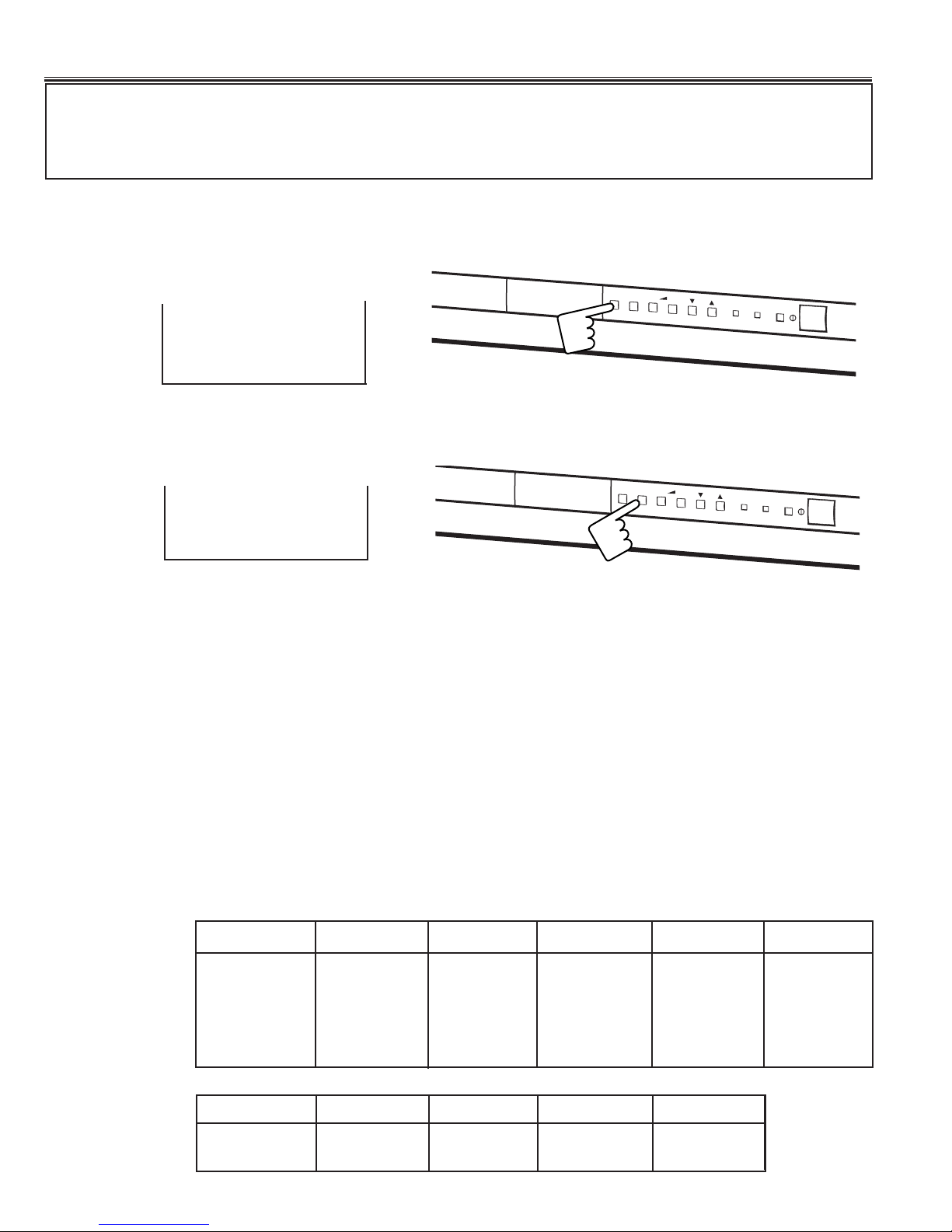
Service Adjustments . . . . . . . . . . . . . . . . . . . . . . . . . . . . . . . . . . . . . . . 9
Service Adjustments with replacing Memory IC (IC802) . . . . . . . . . . 10-12
Service Mode Adjustments . . . . . . . . . . . . . . . . . . . . . . . . . . . . . . . 13-14
Protection Circuit . . . . . . . . . . . . . . . . . . . . . . . . . . . . . . . . . . . . . . . . . 14
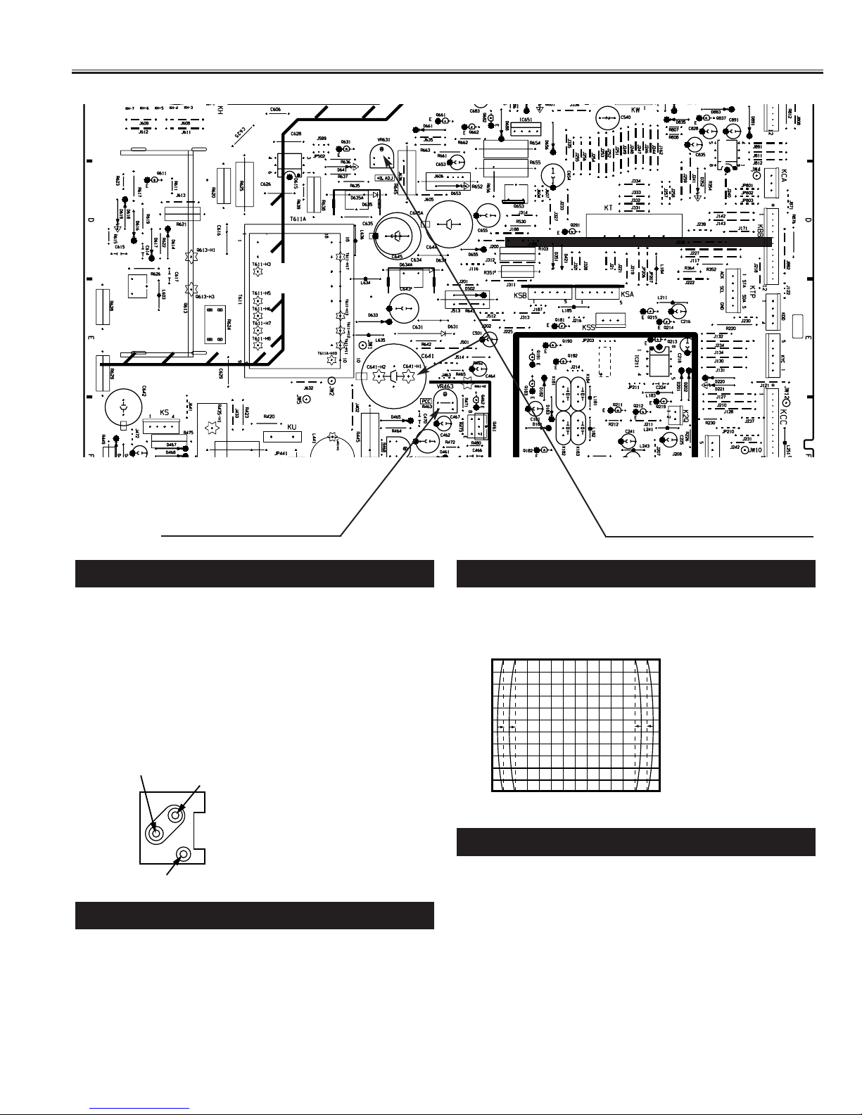
Purity and Convergence Adjustment . . . . . . . . . . . . . . . . . . . . . . . . 15-16
Mechanical Disassemblis . . . . . . . . . . . . . . . . . . . . . . . . . . . . . . . . . . .17
Cabinet Parts List . . . . . . . . . . . . . . . . . . . . . . . . . . . . . . . . . . . . . . . . 18
Chassis Electrical Parts List . . . . . . . . . . . . . . . . . . . . . . . . . . . . . . . 19-32
Safety Notice
SAFETY PRECAUTIONS
1: An isolation transformer should be connected in the
power line between the receiver and the AC line
when a service is performed on the primary of the
converter transformer of the set.
2: Comply with all caution and safety-related notes pro-
vided on the cabinet back, inside the cabinet, on the
chassis or the picture tube.
3: When replacing a chassis in the cabinet, always be
certain that all the protective devices are installed
properly, such as, control knobs, adjustment covers
or shields, barriers, isolation resistor-capacitor net-
works etc.. Before returning any television to the
customer, the service technician must be sure that
it is completely safe to operate without danger of
electrical shock.
X-RADIATION PRECAUTION
The primary source of X-RADIATION in television receiver is the picture tube. The picture tube is specially con-
structed to limit X-RADIATION emissions. For continued X-RADIATION protection, the replacement tube must be
the same type as the original including suffix letter. Excessive high voltage may produce potentially hazardous X
- RADIATION. To avoid such hazards, the high voltage must be maintained within specified limit. Refer to this ser-
vice manual, high voltage adjustment for specific high voltage limit. If high voltage exceeds specified limits, take
necessary corrective action. Carefully follow the instructions for + B1 volt power supply adjustment, and high volt-
age check to maintain the high voltage within the specified limits.
PRODUCT SAFETY NOTICE
Product safety should be considered when a component replacement is made in any area of a receiver.
Components indicated by mark in the parts list and the schematic diagram designate components in which
safety can be of special significance. It is particularly recommended that only parts designated on the parts list
in this manual be used for component replacement designated by mark . No deviations from resistance
wattage or voltage ratings may be made for replacement items designated by mark .

COMP.
VIDEO
A101
TUNER
IIC Bus SOUND
CARRIER TRAP
(5.5MHz)
IC302
VIDEO SW
Y
IC1001
AV SELECTOR
V
L
R
MONITER OUT
AV1 INPUT
V
L
R
S-IN
V
L
R
AV3 INPUT
IC301
COMB FILTER
CY
CLK
IIC Bus
IIC Bus
IF
OUT
Y/COMP.
IC2001
TELETEXT
UNIT
C-IN
IC801
CPU
IC802
MEMORY
IIC Bus
IIC Bus
OSD
(R/G/B)
IIC Bus
4.43
MHz
3.58
MHz
VIDEO OUT R/G/B
V-OUT
H-OUT
L-OUT
R-OUT
IC211
H.V.
Q431
H-DRIVE
IC501
VERT. DEF.
CRT UNIT
IC001
AUDIO AMP.
IC3501
Q-SOUND
IC3401
BBE
SP901
SP902
CRT
V
L
R
AV2 INPUT
(FRONT)
SUB UNIT
MAIN UNIT
AV UNIT
2
57
10
23
1
13
11
L-OUT
R-OUT
17
87
18
L-OUT
R-OUT
X161A
SAW-FILTER
6/7
HEADPHONE
JACK
52
SUB UNIT
TV COMP.
41
3
5
Y
C
7
2
4
13
14
16
8
10
34
3
COMP.
VIDEO
23 25
29 31
37
39
1
C-OUT
34
736
COMP.
VIDEO
40
42 TV-L IN
TV-R IN
32
33 L-OUT
R-OUT
R
L
18/910
138
23/28/30
OSD
(R/G/B)
40/41/42
32
40
3
17
19
CLK
18/19/
20
VIDEO
DET.
IC201
IF/VIDEO/CHROMA
3
23
COMP.
VIDEO
Y- OUT 21
12
R
B
G
42
Q432
H-OUT
DY
VERT. DY
T471
FBT FOCUS
SCREEN
HORIZ. DY
PINCUSHION
CIRCUIT
(Q461,Q462)
8/9
32/34
31/33 5/6
19/
20
From IC801(CPU)
pin-32/34
10/14
48
AUDIO DIRECT OUT
(MONO)
14
13
26
27
IC1920
AUDIO
CONTROL
20/21
FROM
IC801(CPU)
PIN-32/34
IIC BUS
3
SIF
FILTER
(5.5MHz)
SIF IN
OSD
(R/G/B)
YVELOCITY
CIRCUIT
SVM Coil
From
IC302 pin-7
TO Velocity Circuit
140V
L-OUT
R-OUT
Chassis Block Diagrams (MAIN SIGNAL PROCESSING CIRCUIT)
-3-
✽Not equipped

-4-
26
28
7
COLOUR SYSTEM OPTION
KEY SWITCH IN KEY
SWITCH
TV/AV SWITCH OUT
(TV=LOW, AV1/AV2/AV3=HIGH)
SCL (To BUS IC)
34
32
15
29
SDA (To BUS IC)
POWER ON/OFF
PHOTO
COUPLE
(ON=HIGH, OFF=LOW)
IC801
CPU
QXXAVB681
39
42
41
40
1
2
24
3133
20
19
6
23
11
ADJUSTMENT DATA IN
OSD BLK OUT
OSD RED OUT
OSD GREEN OUT
OSD BLUE OUT
DEFLECTION
CIRCUIT
HORIZ. SYNC IN
(ACTIVE=LOW)
VERT. SYNC IN
(ACTIVE=LOW)
POWER PROTECT IN
(POWER ERROR=LOW)
POWER CIRCUIT
etc.
SCL
SDA
IC802
MEMORY
OSC
8MHz CPU OSC OUT
CPU OSC IN
LED
ON-TIMER LED OUT (ON=LOW)
RC SIGNAL IN
(ACTIVE=LOW)
RC PRE-AMP.
10
9
38
IC001
AUDIO AMP.
VIF-M OUT NTSC3.58=HIGH, OTHER=LOW
SIF 4.5MHz
SIF 6.5MHz
SIF 5.5MHz
M (4.5MHz)=HIGH ✽Not used
D/K (6.5MHz)=HIGH ✽Not used
B/G (5.5MHz)=HIGH ✽Not used
17
SOUND MUTE OUT (MUTE ON=HIGH)
IC301
QTC9090ANM
COMB FILTER
VIDEO SW
AFT IN
30
IC201
QXXAVB488M
VIDEO / CHROMA
IC1001
QMM1313BD
AV SELECTOR
A101
TUNER
IC1920
UPC1857ACT
AUDIO CONTROL
IC3401
BBE 5
BBE CONTROL
(OFF=HIGH, MID=Mid., HIGH=LOW))
IC302
VIDEO SW 12
Y/C, COMP. SW
(Y/C=LOW, COMP.=HIGH)
IC3501
Q-SOUND
13
3D SURROUND ON/OFF (ON=HIGH)
14
3D STEREO ON/OFF (ON=HIGH)
3
4
2
10
6
56
20
21
19
20
SCL
SDA
8
9
14
10
SCL
SDA
IC2001
STV5348
TELETEXT
17
16
Chassis Block Diagrams (SYSTEM CONTROL)
✽Not equipped
QXXAVB680

IC Block Diagrams
-5-
IC201 < IF/Video/Chroma> QXXAVB488
VIF IN
IF AGC OUT AFT
TV IN
EXT IN
AUDIO
OUT
33
29
35
26
37
40
32
13
44
43
11
15
16
12
2725242122412819201830239101445
QXXAVB241
SYNC IN
KILLER FILTER
IDENT FILTER
COLOUR APC
AF AMP
AF AMP
4.5/6.0
SIF IO ADJ
BUS
I/F
FM
DET
LIMITTER
B EXIT
INPUT
R EXIT
INPUT
G EXIT
INPUT
V SYNC
TRIG
SYNC
SEP.
SYSTEM
ID
EQ
ELIMINATE
BGP
GENE.
PHASE
CONT
KILLER
DET
LOCK
DET
ID
DET
CHROMA
APC
DET
PAL
SW
SECAM
FF
SELF
ADJ
V.RAMP
AFC
AFC
1H DL
VCXO
ACC
DET
F/F
2ND AMP
CHROMA
BPF
1ST AMP
(ACC)
HPF
AFT
AFT OUT
VIDEO
MUTE
H STOP
H.PHASE
AUDIO MUTE SW
SDA
SCL
FAST BLK
B IN
R IN
B-OUT
R- OUT
G-OUT
G-IN
H-VCC
SECAM REF
V.SIZE SERVICE
SW
H-OSC
SELF ADJ.
CLAMP
50/60 OUT
R
TINT
B
R
DRIVE
BG
ABCL
ABCL
ID CUT BLUEBACK
WHITE
BACK
COLOR
CONTRAST
SERVICE BRIGHT
STATION DET STATION
SYSTEM SET
SYSTEM
IF AGC
DELAY ADJ
DEFEAT
DL TIME
DL FINE
VIDEO
VCC
VIDEO
GND
DEFLECTION
GND
TRAP
SW
D.TRAP
F.TRAP
BLACK STRECH OFF
F AGC
VIDEO
DET
VIF
AMP
APC
DET
ADJ
DET
BLACK
STRECH
VIDEO
TONE
CHROMA
TRAP
VIDEO
MUTE
CLAMP
SHARPNESS
CONTRAST
DELAY
FEF
FILTER
AGC
R-Y IN
B-Y IN
H OUTPUT
SYSTEM
DECODE
BRIGHT
CHROMA
DEMODULATOR
DR/VE
AMP
AFC GAIN
RGB MATRIX
CONTRAST
32 FH
VCO
MUTE
DET
HV
BLK
VERTICAL
COUNTDOWN
HORIZONTAL
COUNTDOWN
EXIT AUDIO
IN
GND
VCC
VIF
SIF
SIF IN
47
48
46
1
8
3
42
52
51
50
49
5
4672 931
38
36
34
39
V-OUT
V-FB
V RAMP
BLK
AUDIO
DIRECT
OUT
AF DC
FB
HI VCC
IF OUT
IF APC
IF VCO
IF VCO
BLACK
PEAK
ACL/CLK Y-SW
OUT
X TAL 4.43
X TAL 3.58
BLACK PEAK
QXXAVB488

-6-
IC Block Diagrams
IC501 < Vertical Output > LA7841
THERMAL
PROTECTION PUMP
UP
AMP
-
+
GND
Ver. Output
Output
Stage Vcc
Non Inv. Input
Inverting
Input
Vcc
Pump Up
Output
LA7841
1234 567
IC001 < Sound Output > LA4270
VIDEO ADC LINE
MEMORY
CLAMP
BPF
BPF
BPF
VERTICAL
ENHANCER
SECAM
4.43 NTSC
DYNAMIC
COMB FILTER
PLL
BPF
BPF
PEDESTAL
CLIP
CORING
CHROMA KILLER
++Y DAC
C DAC
Y-OUT
C-OUT
25
23
1 LINE DOT
IMPROVEMENET
I2C BUS
19
3
8/9
BUS
CLOCK
+
-
4fsc
fsc 4fsc
TC9090ANM
CH1
CH2
Thermal
Shutdown
Over
Voltage
Ripple
Filter
30K
300
30K
300
Vcc
-
+
+
-
Feedback 1
Input 1
Ripple filter
Input side
earth
Input 2
Feedback 2
Output 2
Output side
earth
Power supply
Output 1
LA4270
IC301 <COMB Filter> TC9090ANM
IC1920 <Audio Control> UPC1857ACT
LPF
LPF
26
MFO
29 30 28 24 23 22 21 20 15 19 18 10 9 17
14
13
27
25
1678121116
L
L+R
OUTPUT
SELECTOR
I2C BUS
INTERFACE
OFFSET
VOLUME
BALANCE
CONTROL
MUTE
OFFSET
+
+
+
+
+
+
+
SCLSDAADSDGNDMF1
PS1 PS2 PS3 PS4
PHASE
TRANSFER
EFFECT
CONTROL
2 3 4 5
LF1
TONE
CONTROL
TONE
CONTROL
1/2Vcc
OFL1 OFL2 LBC LTC VOL-C
Lout
Rout
+
+
+
+
Vcc
+
+
+
L+
φ
-R-
φ
R
FC1 FC2 FC3 FC4 LF2 AGND OFR1 OFR2 RBC RTC BAL-C
1/2Vcc
+
-
-
-
+
+
+
Lin
Rin
Mix
φ
UPC1857ACT

-7-
IC Block Diagrams
1
GND
2
3
4
DETR
CTL
DEFR
5
6
CTL
VCAR
R-MIX
7
R-OUT
VCA
8
R-IN
9
APFR
10
HPFR
HPF
LPF
11
LPFR
12
BIASC
LD
–
+
+
HI MID
+
+
+
+
CTL
24 DETL
23
22 DEFL
VCA
21 VCC
20 VCAL
19 L-MIX
18
17
16
L-OUT
L-IN
15
14
13
APFL
HPFL
LPFL
HPF
LPF
+
++
+
MID
LO
+
+–
HI
IC3401 <BBE> QBA3880AFS
87
BUFFER
65
4
3
2
1
Vin1 CTL Vin2 NC
Bias
NC
V
Vout
GND +
IC211, IC302 QNJM2233BD

-8-
IC Block Diagrams
IC1001 < AV Selector > MM1313BD
41
1
7
13
27
MTV-V
V1-V
V2-V
V3-V
STV-V
3
9
5
11
42
0dB 0dB
V1-Y
V2-Y
V1-C
V2-C
MTV-L
2
8
14
25
V1-L
V2-L
V3-L
STV-L
40
4
10
16
MTV-R
V1-R
V2-R
V3-R
26
36
19
20
STV-R
BIAS
SCL
SDA
BIAS
30
GND
I2C LOGIC 28
21
12
6
24 ROUT2ROUT2
S1
S2
ADDRESS
Mute
-6dB
6dB
6dB
32 ROUT1
33
22
LOUT1
LOUT2
-6dB
31
37
29
39 COUT1
CIN1
YOUT1
VOUT2
23
YIN1
34 VOUT1
6dB
38 Vcc
6dB
-6dB
COMB
IC3501 < 3D Surround Processor > MM1369
SIMULATED
STEREO
SIMULATED
STEREO
VIRTUAL AUDIO
QXPANDER PROCESSOR
gm
24 23 22 21 20 19 18 17 16 15 14 13
123456 78910 11 12
Vcc Lin Gl1 Gl2 Gl3 Gl4 Fc Qf1 Qf2 Qf3 Qf4 Lout
Rin Gr1 Gr2 Gr3 Gr4 M/g Ref SPC Qi S/Q Rout Gnd
MM1369AD

-9-
IC802
MEMORY
IC291
SOLDER
SIDE
VIDEO SW
T611
CONVERTER
TRANS.
Q613
POWER. OUT
Q612
POWER.
DRIVE
TELETEXT BOARD
SECAM BOARD
Service Adjustments
MAIN BOARD
Pincushion Adjustment B-Voltage Supply Adjustment
(1) Receive PAL cross hatch pattern.
(2) Select ”DYNAMIC” picture mode with the remote
control VSM (Video Status Memory) button.
(3) Adjust the focus control VR(H) for the best focus
vertical line on the screen center.
(4) Adjust the focus control VR(V) for the best focus
horizontal line on the top of the screen.
(5) Readjust the focus of the items (3) and (4).
FOCUS ADJUSTMENT
FBT
SCREEN VR
FOCUS VR (H)
FOCUS VR (V)
(1) Connect DC meter to C641(+ side) and the ground.
(2) Tune the receiver to an active channel and
synchronized picture. Select DYNAMIC picture mode by
pressing the VSM (Video Status Memory) button on
the remote control .
(3) Adjust B-voltage to be 140 ± 0.5 volt DC by using
VR631.
B-VOLTAGE SUPPLY ADJUSTMENT
(1) Receive the monochrome circular pattern.
(2) Set the brightness and contrast to maximum.
(3) Connect a high voltage probe to anode lead of the
picture tube.
(4) The high voltage must be 30.5KV ± 1KV and less than
33KV at 0 beam current (Brightness and contrast mini-
mum settings).
NOTE:
If the picture tube is replaced, check the high voltage.
HIGH VOLTAGE CHECK
(1) Receive the cross hatch pattern signal.
(2) Adjust so that the vertical lines to become straight by
using VR463.
PINCUSHION ADJUSTMENT

[1] Initializing Procedure
1. Put a new memory IC.
2. Turn on the TV set.
3. Press and hold the TV/AV Selector button on the TV set for more than 2 seconds. The following picture appears on
the screen.
4. Press the MENU button on the TV set while the above On-Screen Display is still on the screen. The following
picture appears on the screen.
This completes the initialization of memory IC.
Following shows the initialized contents of memory data by this procedure.
- Plug & play : No executed
- Inhibit data : Cancelled
- Ch skip data : Cancelled
- Sound volume data : 10/63 steps.
- Volume Lock : OFF
- Tuning Lock : OFF
- Music Mode : OFF
- AV Start : OFF
- Language : English
- AV status : When the memory IC replaced, the CPU writes the initial value of the AV Status
to the replaced memory IC as shown in below table.
-10-
Service Adjustments with Replacing Memory IC(IC802)
Note: The CPU (IC801) and memory IC (IC802) store the service adjustments data and controls data for each circuit.
When the Memory IC(IC802) is replaced, some of the service adjustments should be readjusted to obtain the
best performance. The necessary service adjustments are carried out by using the RC handset. Please set
up the TV set with following steps [1] to [2].
MEMORY CLEAR
ITEM PERSONAL DYNAMIC NATURAL ECO GAME
COLOUR 34/63 34/63 34/63 31/63 28/63
BRIGHTNESS 33/63 33/63 36/63 33/63 33/63
CONTRAST 63/63 63/63 63/63 40/63 50/63
TINT 31/63 31/63 31/63 31/63 31/63
SHARPNESS 31/63 54/63 31/63 24/63 31/63
Press and hold for more than 2 seconds
Video Status
1
Audio Status
ITEM PERSONAL MUSIC TALK NORMAL
BASS 7/15 12/15 4/15 7/15
TERBLE 7/15 12/15 12/15 7/15
-
+
P
MENU
TV/AV
-
+
P
MENU
TV/AV

-11-
Service Adjustments with Replacing Memory IC(IC802)
[2] Required Service Adjustments
Readjust the following service adjustments.
Adjustments Service Mode No. & Item
Horizontal centre adjustment Item 01, H-P
Ver tical centre adjustment Item 02, V-P
Ver tical size adjustment Item 03, V-S
OSD position adjustment Item 04, OSD
RF AGC adjustment Item 05, AGC
AFT adjustment Item 06, VCO
SIF adjustment Item 07, SIF
Grey scale adjustment Item 18-24, DRV
Further adjustment please refer to page 13 and 14.
Following table shows the initial values which have been stored in the CPU ROM, and items for the service
adjustments.
Notes:
+ The initial value that the CPU writes down the CPU ROM data to the memory when replaced the memory IC. TV set
may not operate correctly with this initial value. It is required to set up the fine adjustment for service adjustments
described in the above.
Service mode adjustments table in CPU ROM
NO. ITEM INITIAL
VALUE
RANGE
OF DATA FUNCTION NO. ITEM INITIAL
VALUE
RANGE
OF DATA FUNCTION
01
02
03
04
05
06
07
08
09
10
11
12
13
14
15
16
17
18
19
20
H-Phase (H-Centering) AdjustmentH-P 08 00-15
V-Position (V-Centering) AdjustmentV-P 02 00-07
V-Size AdjustmentV-S 70 00-127
OSD H-Position AdjustmentOSD 01 00-15
RF AGC Adjustment
AGC 64 00-127
VCO (AFT) Adjustment
VCO 128 00-255
SIF VCO AdjustmentSIF 00 00-03
Self Adjustment Mode Setting
SELF 00 00-15
DL Time Adjustment
DLT 02 00-03
DL Fine AdjustmentDL F 01 00, 01
Black Stretch On/Off SettingB-ST 00 00, 01
ABCLABCL 01 00, 01
ABCL GainAB-G 00 0, 01
Trap Frequency AdjustmentTRAP 03 00-03
White Back SettingWBK 00 00, 01
Blue Back SettingBBK 00 00, 01
AFC Gain AdjustmentAFCG 02 00-02
Red Bias AdjustmentRBI 00 00-255
Green Bias AdjustmentGBI 00 00-255
Blue Bias AdjustmentBBI 00 00-255
21
22
23
24
25
26
27
28
29
30
31
32
33
34
35
36
37
38
39
40
100
171
172
Red Drive Adjustment
RD 64 00-127
Blue Drive Adjustment
BD 64 00-127
Drive Adjustment
DRV --
Screen Adjustment
1 LINE --
Y/C Separation
Y/C 11 10,11
AV mode contrast under the no signal condition
VCON 10 00-63
VBRI 20 00-63
DVD Colour Adjustment
DCOL 115 00-255
DVD Tint Offset
DTIN 05 -32 - +32
DVD PAL Colour differential value
DPLC 18 -127 - +127
DVD PAL Tint differential value
DPLT 15 -63 - +63
Manufacturing process flag for DVD
DVD-F 00 00-01
1-HDL through flag
HDL-F 00 00-01
MAT switching flag
MAT-F 00 00-01
NICAM/A2 carrier setting
NICAM 00 00-01
DVD 1 chip colour adjustment
COFF 00 00-03
BBE MID level adjustment
BBE-M 128 00-255
BBE HIGH level adjustment
BBE-H 00 00-255
Y/C IC emphasis setting
ENH 00 00-01
Option setting
CPU Debug Data
CPU Debug Data
Check Code
OPT
R00
R71
R72
255
FF
FF
FF
00-255
00-FFh
00-FFh
00-FFh
AV mode brightness under the no signal condition

-12-
Service Adjustments with Replacing Memory IC(IC802)
[Entering to Service Mode]
1. Press and hold the MENU button on the TV set and press the [1] button on the remote control handset. Following
setting items appears on the screen.
Display for [AGC] AGC adjustment
■00010100 ■
ADDRESS DATA
05 AGC 64
Read Status
Item No. Item Data value
01➔02➔03➔04➔05......172 172➔171➔170➔169➔168......01
Display for [H-P] Horizontal centre adjustment
■00010100 ■
ADDRESS DATA
01 H-P 8
Read Status
Item No. Item Data value
Data value for Red
Display for [DRV] White balance adjustment
■00010100 ■
ADDRESS DATA
23 DRV R 64 B 64
Read Status
Item No. Item
Data value for Blue
To return to normal TV mode, press the MENU button on the TV set or remote control handset.
2. Select item by pressing the TIMER (Item No. UP) or SOUND MUTE (Item No. DOWN) button on the remote control
handset.
3. Adjust data value by pressing the VOLUME + or VOLUME
-
button on the remote control handset.
Example
-
+
P
MENU
TV/AV
0
7
14
8
5
23
6
9/
TIMER TV/AV
TIMER
MENU
P
▲
P
▼
ZOOM

-13-
IC201
IF/VIDEO/CHROMA
IC3801
IF SIGNAL
PROCESSOR
(1) Receive the monochrome circular pattern.
(2) Set the brightness and contrast to normal.
(3) Select [H-P] in the service mode.
(4) Change value to be optimum horizontal centre position.
(5) Exit from the service mode.
Item 01 [H-P] HORIZONTAL CENTRE
Service Mode Adjustments
Horizontal centre
Following adjustments should be carried out when the memory IC is replaced. How to enter the service mode and
adjust values, please refer to “ Entering to Service mode” on page 12.
ROMA
A101
TUNER
MAIN BOARD
IC201 pin-2
Q106
Pin-2
IC201
pin-46
MAIN BOARD
TP-A
(1) Receive the monochrome circular pattern.
(2) Set the brightness and contrast to maximum.
(3) Select [V-P] in the service mode.
(4) Change value to be optimum vertical centre position.
(5) Exit from the service mode.
Item 02 [V-P] VERTICAL CENTRE
Vertical centre
(1) Receive the monochrome circular pattern.
(2) Set the brightness and contrast to maximum.
(3) Select [V-S] in the service mode.
(4) Change value to be optimum vertical size.
(5) Exit from the service mode.
(1) Receive the monochrome circular pattern.
(2) Set the brightness and contrast to normal.
(3) Select [OSD] in the service mode.
(4) Change value to be proper OSD position.
(5) Exit from the service mode.
Item 04 [OSD] OSD POSITION
Item 03 [V-S] VERTICAL SIZE
Vertical size
NOTE: Do not attempt this adjustment with weak signal.
(1) Tune the receiver to most clearest (or strongest) VHF
station in your area. Set the brightness and contrast
controls to maximum. Set the colour control to mini-
mum.
(2) Select [AGC] in the service mode.
(3) Change value until the snow noise just disappears.
Item 05 [AGC] AGC
Item 06 [VCO] AFT
(1) Input the SG signal to collector of Q106.
SG signal frequency : 38.0MHz
SG signal level : 70 dB~75dB
SG signal : COLOUR bar
(2) Connect a short clip between the base of Q106 and
ground. Connect a short clip between TP-A and TP-E.
(3) Connect oscilloscope to pin 2 of IC201.
(4) Select [VCO] in the service mode.
(5) Change value until the voltage to be 4.5 ± 1.0V.
(6) Exit from the service mode.
Item 07 [SIF] SIF
(1) Tune the receiver to the clearest station with System
B/G(5.5MHz) in your area.
(2) Connect DC voltmeter to pin 46 of IC201 and ground.
(3) Select [SIF] in the service mode.
(4) Change value until the voltage to be about 3.0V.
(5) Exit from the service mode.
TP-E

(1) Receive the monochrome circular pattern.
(2) Set the brightness and colour to normal, contrast to
maximum.
(3) Enter to the service mode.
(4) Select No. 18 RBI (Red Bias), No, 19 GBI (Green Bias),
and No. 20 BBI (Blue Bias) and set each data to 0 with
+ or - key.
(5) Select No. 21 RD (Red Drive) and No. 22 BD (Blue
Drive) and set each data to 64 with + or - key.
(6) Turn Screen Control (T471) to minimum (fully counter-
clock-wise).
(7) Select the TV Service Menu No. 24 (Screen
Adjustments).
(8) Advance Screen Control (T471) clockwise to obtain just
visible one color line. If line does not appear, place this
control to maximum (fully clockwise).
(9) Raise each Bias Level with 1, 2, 5, 6, 9 and 0 keys to
obtain just visible white line.
(10) Select the TV Service Menu No. 23 DRV (Drive
Adjustments).
(11) Adjust Red and Blue Drive Levels alternately with 3, 4,
-/-- or RECALL key to produce normal black and white
picture in highlight areas.
(12) Check for proper grayscale at all brightness levels.
To turn off the TV Service Menu display, press the
MENU key.
Note: If Grayscale Adjustment is made after picture tube
replacement, check High Voltage
Items 18
-
24 GREY SCALE
-14-
Service Mode Adjustments
This TV set has a built-in power supply protection circuit.
It is provided to protect the TV set in case of a power supply circuit malfunctions. When something abnormality
occurs during TV reception, the TV set goes to the stand-by mode.
When an abnormality occurs during TV reception, it causes pin 24 of the CPU to go continually Low(less than
0.75V) for about one second. The CPU detects that this has occurred and outputs the signal from pin 15 to
switch off the power supply lines.
■Releasing the protective circuit and restoring power supply
To release the protective circuit and restore power supply, turn the power to the TV set OFF and then ON again
via either the main power switch or the ON-OFF button on the remote control. This will work only if the power
supply trouble was temporary. If there is permanent trouble such as a damaged circuit, power cannot be
restored and the circuit will have to be repaired.
Protection Circuit
Red Bias -
Red Bias +
Green Bias -
Green Bias +
Blue Bias -
Blue Bias +
Press the
MENU
button to exit
from service
mode
Red Drive -
Red Drive +
Blue Drive -
Blue Drive +
0
7
14
8
5
23
6
9
JXMLF
MENU
-/--
PP
A•B
CH SCAN
TIMER TV/AV
P
▲
P
▼
SWAPVSM
BBE BASS
ASM
SURROUND

-15-
Signals: Use a pattern generator which can output red,
green, blue and white raster and crosshatch
pattern signals.
Procedure: Carry out purity adjustment first, and then carry
out convergence adjustment.
Preparation: The deflection yoke may have several
correction magnets attached to its outer
edge. If replacing the picture tube, the
positions of the magnets can be changed and
they can be re-used, so remove these
magnets and keep them safely so that they
do not get lost.
PURITY ADJUSTMENTS
1. Place the picture so that its front faces west.
2. Insert the power plug into a wall outlet, and then turn on
the power for the TV and de-magnetize the TV using its
own degaussing circuit.
3. Loosen the screw which is holding the deflection yoke
(with integrated purity magnets), and them move the
deflection yoke forward as far as it will go. Remove the
rubber wedge at this time.
4. Turn off the red and blue raster so that only the green
raster is on.
5. Adjust the angle between the tabs (wings) on purity
magnets to center the vertical green belt in the picture
tube screen. (See Figures 2 and 3.)
NOTE: This adjustment can only be carried out by
changing the angle, not by rotating the tabs up and
down.
6. Gently move the deflection yoke back to the position
where the green band fills the whole of the picture tube
screen, and then tighten the screw to secure the
deflection yoke in place.
7. If there is any color distortion around the edges, correct
it by attaching magnets to the outer edge of the
deflection yoke. The magnets should be attached so
that the line running from the position of the distortion to
the center of the picture tube intersects the deflection
yoke. The colors on the magnets indicate the north and
south poles of the magnets. Attach the magnets in
whichever direction causes the distortion to
disappear.(See Figures 1 and 4. The south and north
pole positions are shown as a guide.)
8. Switch the screen to red and blue rasters and check that
there is no color distortion. If there is any distortion,
adjust the angles of purity magnets tabs or the forward-
back position of the deflection yoke, or change the
attachment positions of the
correction magnets.
Purity and Convergence Adjustment
CAUTION: The Convergence and Purity adjustments have been made at the factory. Readjustment
should be made only after picture tube or deflection yoke replacement, following the steps below:
GREEN band
Magnet attachment position
Deflection
Yo ke outer edge
Color distortion
Figure 1
Figure 2
Figure 3
Figure 4
Change the angle to adjust
the green band so that it is
centered in the screen.

-16-
Purity and Convergence Adjustment
CONVERGENCE ADJUSTMENT
Preparation: After carrying out purity adjustment and
before proceeding to convergence
adjustment, provisionally insert the rubber
wedge so that there is no vertical or
sideways play in the deflection yoke.
Signals: Display a crosshatch pattern.
1. Red/blue center adjustment
Adjust the angle between the tabs (1) and (2) in Figure
5 and rotate them together until the lines of the red and
blue crosshatch patterns (vertical and horizontal lines)
are superimposed in the center of the screen.
2. Green and red/blue center adjustment
Adjust the angle between the tabs (3) and (4) in Figure
5 and rotate them together until the lines of the green
crosshatch pattern are superimposed with the red/blue
crosshatch pattern (vertical and horizontal lines) which
were superimposed in step 1).
3. Vertical lines at screen center (Red and Blue)
Use the YH control (see Figure 8) at the top of the
deflection yoke to correct the vertical line convergence
at the center of the screen.(See Figure 9.)
4. Vertical lines at screen top and bottom
Use the YHC control (see Figure 8) at the top of the
deflection yoke to correct the vertical line convergence
at the top and bottom of the screen. (See Figure 10.)
5. Horizontal lines at screen top and bottom
Rotate the Deflection yoke to the left or right to correct
the horizontal line convergence at the top and bottom of
the screen. (See Figure 11.)
If vertical lines are intersecting at the top and bottom,
use a screwdriver to adjust the balance coil at the top of
the deflection yoke. (See Figure 12.)
Red
Blue
Figure 6
Red/Blue
Green
Figure 7
Red Blue
Figure 9
YH
YHC
Balance
Coil
YHc
YH
Figure 8
Figure 5
Adjust the angle rotation of tabs
(1) and (2) to align the vertical
and horizontal lines.
Adjust the angle and rotation of
tabs (3) and (4) to align the vertical
and horizontal lines.
Use the YH control to correct.
Red
Blue
Figure 10
Use the YHc control to correct.
Blue
Red
Figure 11
Rotate the DY to correct.
Blue
Red
Figure 12
Use the Balance coil to correct

-17-
Mechanical Disassemblies
CABINET BACK REMOVAL
1. Refer to Figure 1, remove 12 screws.
2. Pull off cabinet back and remove.
CHASSIS REMOVAL
1. Remove cabinet back.
2. Discharge the picture tube anode (2nd anode lead) to the dag
coating (picture tube grounding lead).
3. Disconnect Degaussing coil socket (KE), Picture tube socket,
Deflection yoke connector (KDY), Speaker connectors (KL
and KR), and 2nd anode lead.
4. Remove chassis completely by sliding it straight back.
PICTURE TUBE REMOVAL
CAUTION: Do not disturb the deflection yoke or magnet
assembly on the picture tube neck. Care must be taken
to keep these assemblies intact, unless picture tube is
being replaced . Discharge the picture tube to the coat-
ing before handling the tube.
1. Remove chassis, referring to Chassis Removal instructions.
2. Place cabinet’s front face down on the soft surface.
3. Remove the screw on each corner of the picture tube and
GENTLY lift the picture tube out of the cabinet.
4. Install a replacement picture tube in reverse order.
Properly install the degaussing coil and picture tube ground
ing lead on the picture tube. See Figure 2.
Note: If the Picture Tube is being replaced, mount the
Degaussing Coil on the picture tube. See Figure 2.
Figure 2. Picture Tube Removal
Figure 1. Cabinet Back Removal
ANT. 75Ω
INPUT
L
R
AUDIO
S-VIDEO
AV1
AV3
VIDEO
MONITOR
OUT
L-MONO

ANT. 75Ω
INPUT
L
R
AUDIO
S-VIDEO
AV1
AV3
VIDEO
MONITOR
OUT
L-MONO
Cabinet Parts List
-18-
C2SY
Note: Parts order must contain Service Ref. No., Part No., and descriptions.
1 610 284 7628 ASSY,BUTTON POWER
610 229 8406 SPRING
2 610 284 7758 DEC IND
3 610 284 7635 ASSY,BUTTON UNIT
4 610 284 7734 DOOR
5 610 284 7741 DOOR COVER
6 610 284 7765 DEC SHEET DOOR
7 645 040 4672 BADGE,SANYO
or 645 041 7269 BADGE,SANYO
8 610 291 6065 CABINET FRONT
9 610 284 7833 SPRING PLATE
10 610 284 6041 CABINET BACK
11 610 299 8535 LABEL RATING
12 610 284 7772 DEC SHEET REAR
13 610 256 7670 AC CORD HOLDER
14 645 053 8414 ASSY,REMOCON JXMLF
15 610 284 7277 RC-BATTERY LID
610 299 3790 INSTRUCTIONS MANUAL
Key No. Part No. Description Key No. Part No. Description
-
+
P
MENU
TV/AV
0
7
14
8
5
23
6
9
JXMLF
MENU
-/--
PP
A•B
CH SCAN
TIMER TV/AV
P
▲
P
▼
SWAPVSM
BBE BASS
ASM
SURROUND
1
2
3
4
5
6
7
8
9
10
11
14
12
15
13

-19-
C2SY
OUT OF CIRCUIT BOARD
PICTURE TUBE
Q901 414 011 6508 ASSY,CRT A68QCU259X65
Q901A 645 041 5692 MAGNET,CG.PR
Q901B1 610 233 7891 DY SPACER E2HA
610 290 4154 DY SPACER-F8LZ
Q901B2 610 233 7891 DY SPACER E2HA
610 290 4154 DY SPACER-F8LZ
Q901B3 610 233 7891 DY SPACER E2HA
610 290 4154 DY SPACER-F8LZ
Q901B4 610 233 7891 DY SPACER E2HA
610 290 4154 DY SPACER-F8LZ
COIL
L901 645 040 0261 COIL,DEGAUSSING
MISCELLANEOUS
SP901 645 002 4313 SPEAKER,8
SP902 645 002 4313 SPEAKER,8
W901 645 024 6647 CORD, POWER
645 048 2113 CORD, POWER
W903 610 283 5311 ASSY,WIRE GND CONNECTOR C
610 283 7155 ASSY,WIRE GND CONNECTOR C
610 285 9911 ASSY, PWB, SUB C2SYT
1AA0B10E600G0
TRANSISTOR
Q001 405 011 8401 TR 2SC1740S-Q
405 011 8500 TR 2SC1740S-R
405 011 8609 TR 2SC1740S-S
405 012 2002 TR 2SC1815-GR
405 012 2101 TR 2SC1815-O
405 012 2309 TR 2SC1815-Y
405 157 0505 TR 2SC536NF-NPA
405 151 8705 TR 2SC536NG-NPA
405 020 7501 TR 2SC945A-PA
405 020 7709 TR 2SC945A-QA
405 020 7907 TR 2SC945A-RA
Q1901 405 011 8401 TR 2SC1740S-Q
405 011 8500 TR 2SC1740S-R
405 011 8609 TR 2SC1740S-S
405 012 2002 TR 2SC1815-GR
405 012 2101 TR 2SC1815-O
405 012 2309 TR 2SC1815-Y
405 020 7501 TR 2SC945A-PA
405 020 7709 TR 2SC945A-QA
405 020 7907 TR 2SC945A-RA
Q300 405 011 8401 TR 2SC1740S-Q
405 011 8500 TR 2SC1740S-R
405 011 8609 TR 2SC1740S-S
405 012 2002 TR 2SC1815-GR
405 012 2101 TR 2SC1815-O
405 012 2309 TR 2SC1815-Y
405 157 0505 TR 2SC536NF-NPA
405 151 8705 TR 2SC536NG-NPA
!
!
!
Chassis Electrical Parts List
Ref. No. Part No. Description Ref. No. Part No. Description
Product safety should be considered when a component replacement is made in any area of a receiver.
Components indicated by a mark in this parts list and the circuit diagram show components whose value have
special significance to product safety. It is particularly recommended that only parts specified on the following parts
list be used for components replacement pointed out by the mark.
!
Note: Parts order must contain Service Ref. No., Part No., and descriptions. The main PCB unit will be supplied without tuner and
flyback transformer. They should be ordered separately.
Read description in the Capacitor and Resistor as follows:
CAPACITOR
CERAMIC 100P K 50V
Rated Voltage
Tolerance Symbols:
Less than 10pF
A : Not specified B : ±0.1pF C : ±0.25pF
D : ±0.5pF F : ±1PF G : ±2pF
R : ±0.25-0pF S : ±0-0.25pF E : +0-1pF
More than 10pF
A : Not specified B : ±0.1% C : ±0.25%
D : ±0.5% F : ±1% G : ±2%
H : ±3% J : ±5% K : ±10%
L : ±15% M : ±20% N : ±30%
P : +100-0% Q : +30-10% T : +50-10%
U : +75-10% V : +20-10% W : +100-10%
X : +40-20% Y : +150-10% Z : +80-20%
Rated value: P=pico farad, U=micro farad
Material:
CERAMIC........... Ceramic
MT-PAPER......... Metallized Paper
POLYESTER...... Polyester
MT-POLYEST.....Metallized Polyester
POLYPRO.......... Polypropylene
MT-POLYPRO....Metallized Polypropylene
COMPO FILM.....Composite film
MT-COMPO........Metallized Composite
STYRENE...........Styrene
TA-SOLID........... Tantalum Solid
AL-SOLID........... Aluminium Solid
ELECT................ Electrolytic
NP-ELECT..........Non-polarised Electrolytic
OS-SOLID.......... Aluminium Solid with Organic Semiconductive Electrolytic
DL-ELECT.......... Double Layered Electrolytic
RESISTOR
CARBON 4.7K J A 1/4W
Rated Wattage
Performance Symbols:
A: General B: Non flammable Z: Low noise
Other: Temperature coefficient
Tolerance Symbols:
A: ±0.05% B: ±0.1% C: ±0.25% D: ±0.5%
F: ±1% G: ±2% J: ±5% K: ±10%
M: ±20% P: +5-15%
Rated value, ohms:
K: 1,000, M: 1,000,000
Material:
CARBON........... Carbon
MT-FILM............ Metal Film
OXIDE-MT......... Oxide Metal Film
SOLID................ Composition
MT-GLAZE......... Metal Glaze
WIRE WOUND...Wire Wound
CERAMIC RES.. Ceramic
FUSIBLE RES....Fusible
NOTES:

-20-
C2SY
405 020 7501 TR 2SC945A-PA
405 020 7709 TR 2SC945A-QA
405 020 7907 TR 2SC945A-RA
Q304 405 011 8401 TR 2SC1740S-Q
405 011 8500 TR 2SC1740S-R
405 011 8609 TR 2SC1740S-S
405 012 2002 TR 2SC1815-GR
405 012 2101 TR 2SC1815-O
405 012 2309 TR 2SC1815-Y
405 157 0505 TR 2SC536NF-NPA
405 151 8705 TR 2SC536NG-NPA
405 020 7501 TR 2SC945A-PA
405 020 7709 TR 2SC945A-QA
405 020 7907 TR 2SC945A-RA
Q306 405 011 8401 TR 2SC1740S-Q
405 011 8500 TR 2SC1740S-R
405 011 8609 TR 2SC1740S-S
405 012 2002 TR 2SC1815-GR
405 012 2101 TR 2SC1815-O
405 012 2309 TR 2SC1815-Y
405 157 0505 TR 2SC536NF-NPA
405 151 8705 TR 2SC536NG-NPA
405 020 7501 TR 2SC945A-PA
405 020 7709 TR 2SC945A-QA
405 020 7907 TR 2SC945A-RA
Q307 405 011 8401 TR 2SC1740S-Q
405 011 8500 TR 2SC1740S-R
405 011 8609 TR 2SC1740S-S
405 012 2002 TR 2SC1815-GR
405 012 2101 TR 2SC1815-O
405 012 2309 TR 2SC1815-Y
405 157 0505 TR 2SC536NF-NPA
405 151 8705 TR 2SC536NG-NPA
405 020 7501 TR 2SC945A-PA
405 020 7709 TR 2SC945A-QA
405 020 7907 TR 2SC945A-RA
Q309 405 011 8401 TR 2SC1740S-Q
405 011 8500 TR 2SC1740S-R
405 011 8609 TR 2SC1740S-S
405 012 2002 TR 2SC1815-GR
405 012 2101 TR 2SC1815-O
405 012 2309 TR 2SC1815-Y
405 157 0505 TR 2SC536NF-NPA
405 151 8705 TR 2SC536NG-NPA
405 020 7501 TR 2SC945A-PA
405 020 7709 TR 2SC945A-QA
405 020 7907 TR 2SC945A-RA
Q312 406 000 6804 TR 2SA1015-G(SAN)-TPE2
405 001 7407 TR 2SA1015-O(SAN)
405 001 7605 TR 2SA1015-Y(SAN)
405 004 3109 TR 2SA564A-Q(CU)
405 004 3208 TR 2SA564A-R(CU)
405 151 3304 TR 2SA608NF-NPA
405 006 1707 TR 2SA933S-Q
405 006 1806 TR 2SA933S-R
Q313 405 011 8401 TR 2SC1740S-Q
405 011 8500 TR 2SC1740S-R
405 011 8609 TR 2SC1740S-S
405 012 2002 TR 2SC1815-GR
405 012 2101 TR 2SC1815-O
405 012 2309 TR 2SC1815-Y
405 157 0505 TR 2SC536NF-NPA
405 151 8705 TR 2SC536NG-NPA
405 020 7501 TR 2SC945A-PA
405 020 7709 TR 2SC945A-QA
405 020 7907 TR 2SC945A-RA
Q314 405 011 8401 TR 2SC1740S-Q
405 011 8500 TR 2SC1740S-R
405 011 8609 TR 2SC1740S-S
405 012 2002 TR 2SC1815-GR
405 012 2101 TR 2SC1815-O
405 012 2309 TR 2SC1815-Y
405 157 0505 TR 2SC536NF-NPA
405 151 8705 TR 2SC536NG-NPA
405 020 7501 TR 2SC945A-PA
405 020 7709 TR 2SC945A-QA
405 020 7907 TR 2SC945A-RA
Q315 406 000 6804 TR 2SA1015-G(SAN)-TPE2
405 001 7407 TR 2SA1015-O(SAN)
405 001 7605 TR 2SA1015-Y(SAN)
405 004 3109 TR 2SA564A-Q(CU)
405 004 3208 TR 2SA564A-R(CU)
405 151 3304 TR 2SA608NF-NPA
405 006 1707 TR 2SA933S-Q
405 006 1806 TR 2SA933S-R
Q316 405 011 8401 TR 2SC1740S-Q
405 011 8500 TR 2SC1740S-R
405 011 8609 TR 2SC1740S-S
405 012 2002 TR 2SC1815-GR
405 012 2101 TR 2SC1815-O
405 012 2309 TR 2SC1815-Y
405 157 0505 TR 2SC536NF-NPA
405 151 8705 TR 2SC536NG-NPA
405 020 7501 TR 2SC945A-PA
405 020 7709 TR 2SC945A-QA
405 020 7907 TR 2SC945A-RA
Q342 405 011 8401 TR 2SC1740S-Q
405 011 8500 TR 2SC1740S-R
405 011 8609 TR 2SC1740S-S
405 012 2002 TR 2SC1815-GR
405 012 2101 TR 2SC1815-O
405 012 2309 TR 2SC1815-Y
405 157 0505 TR 2SC536NF-NPA
405 151 8705 TR 2SC536NG-NPA
405 020 7501 TR 2SC945A-PA
405 020 7709 TR 2SC945A-QA
405 020 7907 TR 2SC945A-RA
Q3505 405 011 8401 TR 2SC1740S-Q
405 011 8500 TR 2SC1740S-R
405 011 8609 TR 2SC1740S-S
405 012 2002 TR 2SC1815-GR
405 012 2101 TR 2SC1815-O
405 012 2309 TR 2SC1815-Y
405 157 0505 TR 2SC536NF-NPA
405 151 8705 TR 2SC536NG-NPA
405 020 7501 TR 2SC945A-PA
405 020 7709 TR 2SC945A-QA
405 020 7907 TR 2SC945A-RA
Q3506 405 011 8401 TR 2SC1740S-Q
405 011 8500 TR 2SC1740S-R
405 011 8609 TR 2SC1740S-S
405 012 2002 TR 2SC1815-GR
405 012 2101 TR 2SC1815-O
405 012 2309 TR 2SC1815-Y
405 157 0505 TR 2SC536NF-NPA
405 151 8705 TR 2SC536NG-NPA
405 020 7501 TR 2SC945A-PA
405 020 7709 TR 2SC945A-QA
405 020 7907 TR 2SC945A-RA
Q3521 405 011 8401 TR 2SC1740S-Q
405 011 8500 TR 2SC1740S-R
405 011 8609 TR 2SC1740S-S
405 012 2002 TR 2SC1815-GR
405 012 2101 TR 2SC1815-O
Ref. No. Part No. Description Ref. No. Part No. Description
Table of contents
Other Sanyo TV manuals

Sanyo
Sanyo C29FS51 User manual

Sanyo
Sanyo HT30547 User manual

Sanyo
Sanyo PDP-42XR9DA User manual

Sanyo
Sanyo C21ZM40 User manual

Sanyo
Sanyo CW21CF1 User manual

Sanyo
Sanyo LCD-DP55441 User manual

Sanyo
Sanyo FVM4612 User manual

Sanyo
Sanyo CE14AT3-C User manual

Sanyo
Sanyo HT32744 Product information sheet

Sanyo
Sanyo CP29KX2Z User manual

Sanyo
Sanyo CP14CE1 User manual

Sanyo
Sanyo DS32424 User manual

Sanyo
Sanyo CE29FFV1-F User manual

Sanyo
Sanyo CP20SR1Z User manual

Sanyo
Sanyo DS35224 User manual

Sanyo
Sanyo CE21D3-C User manual

Sanyo
Sanyo CE30LC3-C User manual

Sanyo
Sanyo C1 4ZA25 User manual

Sanyo
Sanyo FVM4012 User manual

Sanyo
Sanyo DP19649 - 720p 18.5" LCD HDTV User manual