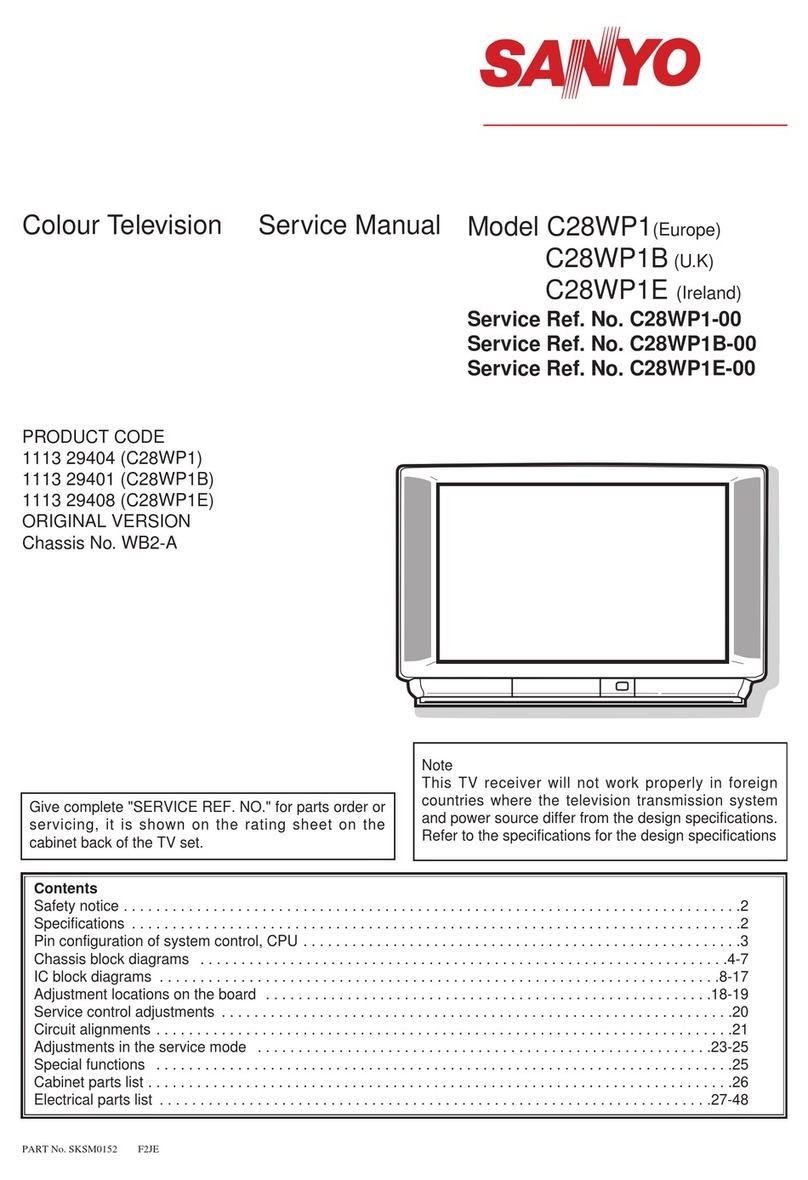
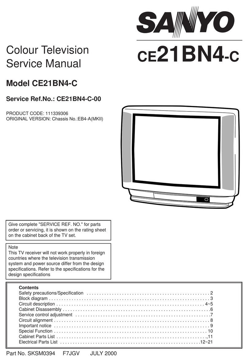
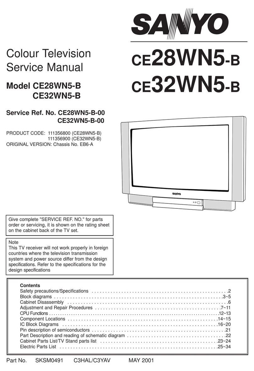
Sanyo CE32WN5F-C User manual

Part No. SKSM0613 C3YFV OCTOBER 2002
Colour Television
Service Manual
Model CE32WN5F-C
Service Ref. No. CE32WN5F-C-04
CE32WN5F-C-06
PRODUCT CODE: 111356910
ORIGINAL VERSION: Chassis No. EB7-A
Give complete "SERVICE REF. NO." for parts
order or servicing, it is shown on the rating sheet
on the cabinet back of the TV set.
Note
This TV receiver will not work properly in foreign
countries where the television transmission
system and power source differ from the design
specifications. Refer to the specifications for the
design specifications
CE32WN5F-C
Contents
Safety precautions/Specifications ..................................................................................................................2
Block diagrams ..............................................................................................................................................3
Cabinet Disassembly......................................................................................................................................4
Adjustment and Repair Procedures............................................................................................................5~9
CPU Functions ..............................................................................................................................................................................10~11
Component Locations ............................................................................................................................12~13
IC Block Diagrams..................................................................................................................................14~18
Pin description of semiconductors................................................................................................................19
Part Description and reading of schematic diagram ....................................................................................20
Cabinet Parts List/TV Stand parts list ..........................................................................................................21
Electric Parts List....................................................................................................................................22~26
Please use Schematic Diagram SKP20370 with
this Service Manual.

-2-
C3YFV
SAFETY PRECAUTION
X-RADIATION PRECAUTION
The primary source of X-RADIATION in the television receiver is the picture tube. The picture tube is specially
constructed to limit X-RADIATION emissions. For continued X-RADIATION protection, the replacement tube
must be the same type as the original including suffix letter. Excessive high voltage may produce potentially
hazardous X-RADIATION. To avoid such hazards, the high voltage must be maintained within specified limit.
Refer to this service manual, high voltage adjustment for specific high voltage limit. If high voltage exceeds
specified limits, take necessary corrective action. Carefully follow the instructions for +B1 volt power supply
adjustment, and high voltage adjustment to maintain the high voltage within the specified limits.
PRODUCT SAFETY NOTICE
SPECIFICATIONS
Product safety should be considered when a component replacement is made in any area of a receiver.
Components indicated by mark in the parts list and the schematic diagram designate components in which
safety can be of special significance. It is particularly recommended that only parts designated on the parts list in
this manual be used for component replacement designated by mark . No deviations from resistance wattage
or voltage ratings may be made for replacement items designated by mark .
!
!
!
1: An isolation transformer should be connected in the
power line between the receiver and the AC line
when a service is performed on the primary of the
converter transformer of the set.
2: Comply with all caution and safety-related notes
provided on the cabinet back, inside the cabinet, on
the chassis or the picture tube.
3: When replacing a chassis in the cabinet, always be
certain that all the protective devices are installed
properly, such as, control knobs, adjustment covers
or shields, barriers, isolation resistor-capacitor networks
etc. Before returning any television to the customer,
the service technician must be sure that it is completely
safe to operate without danger of electrical shock.
Power source AC 220~240V, 50Hz
Television system System B/G, I, L/L’
Colour system PAL/SECAM/NTSC4.43 (PAL/NTSC4.43/MTSC3.58 INAV MODE)
Receiving channel UHF: #21~69
Aerial input impedance 75ohm
Rear AV terminal
AV1: CENELEC standard
INPUT: Composite video, RGB and Audio L/R
OUTPUT: TV-output with composite video and audio L/R
AV2: CENELEC standard
INPUT: Composite video, RGB, S-VHS and Audio L/R
OUTPUT: Monitor output with composite video and Audio L/R
Front AV terminal
AV3: RCA jacks
INPUT: Composite video and Audio L/R
Sound output(Music) 12 x 2
Dimensions (WxHxD) 880 x 577.5 x 567mm
Weight 46.3 Kg

-3- C3YFV
BLOCK DIAGRAM
This is a diagram for all models and therefore differs slightly from the actual block diagram.
1 5
8/10
SP902
SP901
SPEAKER
IC001
AUDIO-OUT
<TDA7263M>
IC201
IF/VIDEO/CHROMA/DEF
<TB1251>
80
79
54
26
27
20
21
22
23
IF-IN X132
SIF-IN
A101
TUNER
IF
SCL
SDA
Video-Out
SIF-OUT
K1002
SCART SC2
K1001
SCART SC1
48
46
58
61
57
56
55
R/G/B-IN
SCL
SDA
47
39
12
13
14
CRT
HEATER
200V
Q701
Q711
Q721
B
R
GPICTURE
TUBE
H.V
FOCUS/SCREEN
T451 FLYBACK
R
G
B
Q431
Q432
H-OUTPUT
D.Y
V-OUT
H-OUT
6
3
IC501
V-OUTPUT
<LA7846>
IC1201
AV-VIDEO-SW <LA7954>
IC1401
RGB-SW
<TC4053BF>
BLK
R
G
B
45
18
17
16
15
34
33
54
11
21
20
8
1
19
MUTE
IC801
CPU
IC3451
NICAM/
STEREO
RC-IN
A1901
RC RECEIVER
KEY-IN
KEY SW
SDA
SCL
SDA
SCL
IC803
MEMORY
PROTECT
POWER
D641
9V
IC642
D647
5V-1
27V
IC643
Q661
Q651
Q682
Q685
25V
145V
Q641
Q686
D615
13
14
11
18
15
5
3
2
8
Q611
SW901
D603-D606
AC
C607
Q613
Reg.
C-IN
C-IN
Y-IN
Video/
Y-IN
Video/Y-Out
Video-IN
R/G/B-OUT
T611
CONVERTER
D637
D646
5V
IC641
Q666
AERIAL
5V
12
60 61
71
9816
1/3/13
2/5/12
4
14
15
SCL
SDA
45
R
G
B
51/53 M-OUT
R/G/B-IN
11/7/15
7/11/15
19
12
13
C-IN
C-OUT
15
15
53
D441
SCREEN
WIDTH
CONTROL
4H-BLANK
L461
L462
Q461
Q462
I2C BUS
CONTROL
EW-OUT 33
X131
75
76 19
20
20
12
Q642
-27V
10
Q645
Q643
Outline

-4-
C3YFV
(A) (A)
CABINET DISASSEMBLY
CABINET BACK DISASSEMBLY
1. Remove 9 screws(A) for 32”
2. Pull out the cabinet back.
(A)
(A)
(A)
(A)
(A)
(A)
(A)
ANT.75Ω
FRONT
/DAVANTI
L/S
R/D
INT EXT/EST
REAR
/POSTERIORE

-5- C3YFV
Procedure for reinitialising IC803 (If replacing IC803 start at step 7)
1. Press the Normal button on the remote control and then press the P▼ button on the TV - wait for
several seconds and the channel data will disappear.
2. Switch to AV Mode (to make viewing OSD easier)
3. Press the button.
4. Use the P▼ button to highlight “otres”, press the button.
5. Use the P▼ button to highlight “Idiorna del OSD”, press the until OSD language ENGLISH appears.
6. Press the button repeatedly until the menu mode is exited.
7. Reset the options menu. To select the options menu press and hold the F/OK button on the remote control
and then press the P▼ button on the TV SET; the menu will appear. Set the options to match the drawing
below:
a) Press the P▼ button to highlight the option you wish
to change.
b) Press the button to match the setting in the table.
c) When all options have been set, exit the menu by pressing
the RECALL button. The data is automatically
stored.
8. Set up the service adjustments as described on pages 6 to 9.
9. Retune all stations (see advise on page 7 for resetting Plug and Play)
Procedure for reinitialising IC803
1. Press the Normal button on the remote control and then press the P▲ button on the TV (note: if you
press the P▼ follow procedure as described above instead). There is no need to set the OSD language or
alter the option table.
2. Set up the service adjustments as described on pages 6 to 9.
3. Retune all stations (see advise on page 7 for resetting Plug and Play)
?
i
MENU/
i
MENU/
REINITIALISATION OF MEMORY IC803
FOR CE32WN5F-C-04
ON-TIMER ON
SORT MODE SORTING
P&P ON
WEL.TEXT ON
COMB FILTER OFF
BBE OFF
AUTOVOLUME OFF
HEADPHONE OFF
COUNTRY UK
WIDE ON
OPTION
ADJUST : EXIT : RECALL
Option settings for CE32WNF5-C-04
FOR CE32WN5F-C-06

-6-
C3YFV
SERVICE ADJUSTMENTS
[After replacing the Memory IC (IC803)]
The memory IC, IC803, stores the service adjustments data for each circuit, therefore, when the memory IC is
replaced, it should be programmed by using “OPTION SETTING” on previous page and the following adjustments.
ADJUSTABLE SERVICE ADJUSTMENT
REGULAR
IMAGE
To enter to the Service Mode
+ Press and hold the GREEN button on the remote control and then press the P▼button inside of the door. Press
the P▼ button to highlight the mode required (Regular, Image, others and TB12**). Then press the F/OK button to
select the mode.
IMPORTANT NOTICE
Do not attempt to adjust service adjustments not listed on the above otherwise it may cause
loss of performance and product safety.
Item No. OSD Description
1 P V-C P Vertical Position Adjustment
2 P H-P P Horizontal Position Adjustment
3 P V-L P Vertical Linearity Adjustment
4 P VSC P Vertical S-Correction Adjustment
5 P V-A P Vertical Size Adjustment
6 P H-S P Horizontal Size Adjustment
7 P E-P P Pin Cushion Adjustment
8 P E-T P Trapezoid Distortion Adjustment
11 P ECT P Top Corner Correction Adjustment
12 P ECB P Bottom Corner Correction Adjustment
13 P HPA P Parallelogram Distortion Adjustment
Item No. OSD Description
1 AGC AGC Adjustment
2 -- Cut-Off Drive Adjustment
3 GRY G-Drive Adjustment (white balance)
4 GRY B-Drive Adjustment (white balance)
5 CTR Contrast Adjustment (use factory setting)(for factory use)
6 -- Screen Adjustment mode
8 OSD OSD Positioning Adjustment
Note: Some items of the service adjustments for this chassis are controlled by the CPU, IC801, and the
adjustments are carried out by using the RC handset.
The available adjustment items are as follows;
Image : This can be adjusted for picture images/shapes.
Regular : This can be adjusted for the service adjustment.
other : This is for factory setting. DO NOT ADJUST.
TB1251 : This is for the factory setting. DO NOT ADJUST.

-7- C3YFV
Re tuning channels
1. Press the button, use the P▼ button to highlight “Preset”.
2. Press the button.
3. Highlight “Tuning” (you may need to use the P▼ button)
4. Press the button.
5. Highlight “Auto” (you may need to press the button)
6. Press the P▼ button to select CH:***
7. Press the button.
8. The TV will auto sort the channels
Re setting plug and play
Repeat steps 1 to 7 above but before any stations are found press the button to cancel presetting.
Switch off the TV set with the Mains ON/OFF button. When the TV set is next switched on it will plug and play.
To select the mode and service item and change data value
+ Highlight the desired adjustment mode by using the P▲or P▼button and then press the F/OK button.
+ To select the adjustment item, use the P▲or P▼button.
+ To change the service data, use the Volume -(LEFT) or Volume + (RIGHT) button.
+ The data which is set in the service mode is stored into the memory IC automatically.
Exit from the Service Mode
+ Press the RECALL button or turn off the TV set by using the Mains switch.
REGULAR
1, AGC 38
Adjustment No.
and Item name Adjustment Data
IMAGE
1. PV-P 1F
Adjustment No.
and Item name Adjustment Data
REGULAR mode IMAGE mode
?
i
MENU/
i
MENU/

-8-
C3YFV
ADJUSTMENTS
IMPORTANT NOTICE
Do not attempt to adjust the following service adjustments except when adjustments are required in servicing
otherwise it may cause loss of performance and product safety.
1. Receive white raster pattern.
2. Set controls to normal.
3. Connect digital voltmetre to test point TP-B and GND.
4. Adjust voltage to 145 ±0.5V by using VR641.
1. Input and tune an RF signal which is UHF to the clear-
est station.
2. Connect digital voltmetre to test point TP-A and GND.
4. Enter to the service mode and select mode “REGU-
LAR”, and select item no.1 “REGULAR 1, AGC”.
5. Press the LEVEL+ or LEVEL - button to adjust volt-
age to be 3.2Vdc.
By using FOCUS VR, adjust focus control for well
defined scanning lines.
SCREEN ADJUSTMENT
1. Receive black & white pattern.
2. Enter to the service mode and select mode “REGU-
LAR”, and select item no. 2 “REGULAR 2, CUT”. The
horizontal line will appear on the screen.
3. Set the SCREEN VR for one colour to be just visible.
4. Using the numeric buttons shown set each colour to
minimum by decreasing to the point where any further
decrease resets the adjustment to maximum value.
BIAS ADJUSTMENT
5. By using the buttons 1, 2, 4, 5, 7, 8 on the remote
control, adjust the line to be white.
The key allocation is as follows;
Button No. Operation
1 Increase Red
2 Decrease Red
4 Increase Green
5 Decrease Green
7 Increase Blue
8 Decrease Blue
DRIVE ADJUSTMENT
6. Select item no.3 “REGULAR 3, GRY” (G-Drive) or 4
“REGULAR 4, GRY” (B-Drive) and adjust both initially
to 40.
7. Change data value of each item by using LEVEL + or
LEVEL - button to obtain the proper white balance.
PCC ADJUSTMENT
1. Receive cross hatch pattern and set screen mode to
“FULL”.
2. Enter to the service mode and select mode “IMAGE”,
and select item no. 7 “IMAGE 7.P E-P”.
3. Press the LEVEL+ or LEVEL - button to adjust the
vertical line to be straight.
TRAPEZOID ADJUSTMENT
1. Receive cross hatch pattern and set screen mode to
“FULL”.
2. Enter to the service mode and select mode “IMAGE”,
and select item no. 8 “IMAGE 8.P E-T”.
3. Press the LEVEL+ or LEVEL - button to correct the
trapezum distortion of the vertical line.
PCC ADJUSTMENT
GREY SCALE ADJUSTMENT
FOCUS ADJUSTMENT
AGC ADJUSTMENT
+ B VOLTAGE ADJUSTMENT
-9- C3YFV
C3YFV
CORNER ADJUSTMENT
1. Receive cross hatch pattern and set screen mode to
“FULL”.
2. Enter to the service mode and select mode “IMAGE”,
and select item no. 11 “IMAGE 11.P ECT” for top cor-
ner adjustment OR item no. 12 “IMAGE 12.P ECB for
bottom corner adjustment.
3. Press the LEVEL+ or LEVEL - button to correct the
distortion of the vertical line around the corners.
HORIZONTAL CENTRING ADJUSTMENT
1. Receive circular pattern and set screen mode to
“FULL”.
2. Enter to the service mode and select mode “IMAGE”,
and select item no. 2 “IMAGE 2.P H-P”.
3. Press the LEVEL+ or LEVEL - button to adjust the
horizontal centre.
HORIZONTAL WIDTH ADJUSTMENT
1. Receive circular pattern and set screen mode to
“FULL”.
2. Enter to the service mode and select mode “IMAGE”,
and select item 6 “IMAGE 6.P H-S”.
3. Press the LEVEL+ or LEVEL - button to adjust the
horizontal width.
1. Receive circular pattern and set screen mode to
“FULL”.
2. Set controls for brightness and contrast to maximum.
3. Connect high-voltage meter to the anode of CRT and
GND.
4. Confirm that voltage is 30.5±1.0kV for 24” model
VERTICAL CENTRING ADJUSTMENT
1. Receive circular pattern and set screen mode to
“FULL”.
2. Enter to the service mode and select mode “IMAGE”,
and select item no. 1 “IMAGE1.P V-C”.
.3 Press the LEVEL+ or LEVEL - button to adjust the
vertical centre.
VERTICAL HEIGHT ADJUSTMENT
1. Receive circular pattern and set screen mode to
“FULL”.
2. Enter to the service mode and select mode “IMAGE”,
and select item no. 5 “IMAGE 5.P V-A.
3. Press the LEVEL+ or LEVEL - button to adjust the
vertical height.
1. Receive circular pattern and set screen mode to
“FULL”.
2. Enter to the service mode and select mode “REGU-
LAR”, and select item no. 8 “REGULAR 8 OSD”. The
OSD test bar will appear on the top of screen.
3. Press the LEVEL+ or LEVEL - button to adjust prop-
er OSD positioning.
❚❚❚❚❚❚❚❚❚❚❚❚❚❚❚❚❚❚❚❚
OSD POSITIONING ADJUSTMENT
VERTICAL ADJUSTMENT
HIGH-VOLTAGE CONFIRMATION
HORIZONTAL ADJUSTMENT

-10-
C3YFV
CPU PORT FUNCTIONS
Pin No. Function Name Function IN/OUT
1 RC IN RC Signal Input IN
2 RESET Reset Input IN
3 50/60 50/60Hz output 50Hz:H OUT
4 H-BLK H-Blank (on/off?) OUT
5 V-BLK --
6 AV-SW2 Option SW2 --
7 AV-SW1 Option SW1 --
8 KEY IN Key switch signal input IN
9 H-P
10 RELAY To operate degauss circuit OUT
11 PROTECT Power failure detect input “L” error IN
12 HP-MUTE OUT
13 BBE OUT
14 ? OUT
15 B-OUT Blue output OUT
16 G-OUT Green output OUT
17 R-OUT Red output OUT
18 FB-OUT Fast Blanking output OUT
19 SDA SDA IN/OUT
20 SCL SCL OUT
21 VDD Power --
22 Not used --
23 Not used --
24 Not used --
25 AVDD3 Analogue VDD of PLL --
26 TEST0 Test --
27 MCFM Test --
28 --
29 TXCF Analogue pin for Teletext slicerline PLL --
30 --
31 AVDD2 Analogue power supply --
32 Not used --
33 Video input (H.F) IN
34 Video input (L.F.) IN
35 Not used --
36 Not used --
37 Not used --
38 PXFM Analogue pin for the Display Pixel Frequency Multiplier --
39 VDDA --
40 H-SYNC Horizontal Sync. Input IN
41 V-SYNC Vertical Sync. Input IN
42 ACK Answer for status OUT
43 STATUS Request for BUS open IN
44 INGNOR Not Used --
45 MUTE Sound Mute on/off switch OUT
46 L/L’ Not used OUT
47 LED Led drive OUT
48 S-VHS-SW Not used --
49 H-PHASE Not used --
50 OSC Clock oscillator IN

-11- C3YFV
C3YFV
Pin No. Function Name Function IN/OUT
51 OSC Clock oscillator IN
52 AGC Auto gain control IN
53 P-TTAR1 Pittari switch (Natural wide) OUT
54 POWER & RL Power & relay On/Off control OUT
55 8PIN (SC2) AV2 Scart function input IN
56 8PIN (SC1) AV1 Scart function input IN

-12-
C3YFV
COMPONENT LOCATIONS
T451
L462
T431
Q613
Q641
C607
R602 R637
T611
TP-B
Q432
IC501
C501
C502
VR641
IC643 IC642
IC641
IC803
KA KH
IC801
IC3451
IC001
T131
A101
K1003
KCPA
TP-A
IC1201
KP IC201
X132X131
K1002 K1001
SW1951 SW1952 SW1953 SW1954
A1901A
SW691
K19FF
C691
L691
PS691
F691
K19E K19F
RL691
K19A
SW1955 SW1956 SW1957 K1101
K1921
K19R
K19L
K19H
K19G
IC1931
C1936
C1937
C1942
C1941
C1926 C1927
L684
K7P K7Q
C751
K7EM
Q701
K701-L
K7M
Q711
R711
Q721
R724
C710
K7D1
R704
MAIN BOARD / FRONT BOARD / CRT BOARD

-13- C3YFV
C3HBL/HBLD
IC BLOCK DIAGRAMS
IC001 TDA7263M <Audio Output>
GND
6
4
58OUT R
OUT L
RF1
RF2
RF3
RF4
RF1 27K
CF COUPL
IN +R
IN -R
SUPPLY
VOLTAGE TURN-ON
AND-OFF
MUTE
REFERENCES
IN -L
IN +L L
Tj
TH
PROTECTION
SC
PROTECTION
RF1 27K
CF COUPL
9
3
1+
-
2
R
+
-
10
TDA7263M
IC501 LA7846N <Vertical Output>
AMP
12 3 4 5 6 7 8 9 10
THERMAL
PROTECTION PUMP
UP
NC
Negative supply
Output
Output
stage Vcc
Inverting
input
Non inverting
input
Pump up Out
Vcc
NC
NC
LA7846N

-14-
C3YFV
IC201 TB1262F <IF/Video/Chroma/Def.>
45 35 50 41 40 39 37 33 28 47 46 11 25 17
HVcc (9V)
Dig.VDD
Dig GND
HD SCP OUT
VD
H OUT
FBP IN
EW OUT
EHT IN
V OUT
V RAMP
YC Vcc (5V)
RGB Vcc (9V)
YC GND
32
26
27
31
20
23
22
21
18
14
13
12
34
6
7
9
80
79
77
76
75
72
SAW SAW
Bed pin
SCL
SDA
ABCL IN
Ysm
EXT.B IN
EXT.G IN
EXT.R IN
VM OUT
B OUT
G OUT
R OUT
CW OUT
X'tal
APC Filter
S-Filter
PIF IN
PIF IN
NC
SIF IN
SIF IN
IF GND
42
43
62
54
59
56
57
55
48
49
44
51
52
53
19
36
66
61
58
68
H.AFC
DC resistor
BLACK det
YS(YCbCr)
cb2/B in
cb3 in
cr3 in
Y3/CVBS3 in
Y/CVBS1 in
c in
IF DET OUT
DAC 1
DAC 2
DAC 3
cr out
cb out
Y/MON out
cbr2/R in
Y2/CVBS2/G
Syncout
H,V Sync
AFC1/HAFC gain
V freq
wide blanking
H,drive
AFC2
PalaG
Baw
YUVSwitch
Y/C
YCbCr2
YCbCr3
V/EW
-EW-
corner(T/B)
Size
Trapeze
Parabola
-V-
Size
VCentre
VLinear
V-S
I2C Bus
IF
Y2 Proc.
Black stretch
DC Resistor
WPL / A.C./
WPS
UV Proc.
BBTINT
Colour
Contrast
RGB Proc.
YUV->RGB /Switch
Cutoff/Drive
Chroma
PAL/
NTSC/
SECAM
Y1 Proc.
c-trap
y delay
RGB
->YUV
PIF/SIF
-1st SIF-
QSS demo
AM demo*
-PIF-
VCO
S-Trap
AFT(to BUS)
neg/pos*
SIF
BPF
FM/(AM)
466746778169371737065
DC NF
SIF IN
SIF OUT
PIFVCO F
Loop Filter
IF AGC
RF AGC
IF Vcc (5V)
FM Filter
IF Vcc (9V)

-15- C3YFV
C3HBL/HBLD
IC3451 TDA9875A <NICAM & Stereo Sound Decoder>
SUPPLY
SOUND IF
(SIF)
ANALOG
SCROSSBAR
SWITCH
NICAM
DECODER
DEMATRIXCLOCK
PEAK
DETECTION LEVEL
ADJUST LEVEL
ADJUST
ADC(2)
DAC(2)
SUPPLY
DAC
SUPPLU DAC
REFERENCE
SUPPLY
OPERATIONAL
AMPLIFIERS
AUDIO PROCESSING
DAC(2)
DAC(2)
TEST
TDA9875
DIGITAL
SUPPLY
DIGITAL
SELECT
I2C BUS
AUDIO
INTERFACE
TIMING
DETECT DAC
NICAM
DEMODULA-
TION
FM(AM)
DEMODULA-
TION
IDENTIFICA-
TION
I2C BUS
INTERFACE INPUT SWITCH
AGC, ADC
SIF1
SIF2
12
10
9
20
3
13
4
5
18
17
21
27
SDI1
SDI2
SDO1
SDO2
SCK
WS
VDDD1
VDDD2
VSSD1
VSSD2
CREST
TEST1
TEST2
SYSCLK
XRALO
XTALI
SDA
SCL
ADDR2
ADDR1
P2
P1
26
25
24
22
23
15
64
14
49
16
28
30
57
58
60
61 MOL
MOR
AUXOL
AUXOR
CREST
CREST
CREST
Vref(n)
Vref(n)
Vref2
VSSG
VSSA2
VDDA2
PCAPL
PCAPR
CAPR2
CAPR1
CAPL1
CAPL2
LOL
LOR
SCOL2
SCOR2
SCOL1
SCOR1
MOMOIN
EXTIL
EXTIR
SCIL2
SCIR2
SCIL1
SCIR1
PCLK
NICAM
Iref
Vref1
VSSA1
VDDA1
Vtune
50
53
59
CREST
56
40
39
46
35
43
38
55
54
44
45
41
42
62
63
52
51
48
47
29
32
31
37
36
34
33
1
2
8
11
6
7
19

-16-
C3YFV
PIN DESCRIPTION OF SEMICONDUCTORS
A
K
C
BE
C2
C1
B1 B2
E
C
CBE
KA
C
B
E
B2
B1
C1 C2
E
E
B
C
B2
B1
C1 C2
E
B2
B1 C1
C2
E1
E2
K
AA
A
KK
K
A
K
A
C
BECBEC
B
E
1
2
3
4
5
6
Index
12N
Index Index
12N
2
13
(IN) (OUT)
(GND)
21 4
2
1
3
Index
1
N
Index 1
N
Index 1
N
Index 1
N
Index 1
N
Index
1N
2
131
232
1
3
RESET GND
Vdd
5
3
D
GSD
G
S
K: Cathode
A: Anode
C: Collector
B: Base
E: Emitter
D: Drain
G: Gate
S: Source
●Diode
●Transistor/FET
●IC
E1
C2
E2 C1
B2
B1
Index
●Diode
●Transistor/FET
●IC
FET

-17- C3YFV
C3YFV
PARTS DESCRIPTION AND READING IN SCHEMATIC DIAGRAM
1. The parts specification of resistors, capacitors and
coils are expressed in designated code. Please
check the parts description by the following code
table.
2. Some of transistors and diodes are indicated in
mark for the substitution of parts name. Please
check the parts name by the following code table.
3. Voltages and waveforms were taken with a video
colour bar signal(1Vp-p at 75 ohms terminated) and
controls to normal.
4. Voltages were taken with a high-impedance digital
voltmetre.
Example 2000 K K 1000 BG
Characteristic
Example 160 E M 10
Capacitance value
Tolerance
Type
Rated voltage
Excepting electric capacitors, all
capacitance values of less than 1
are expressed in µF and more
than 1 are in pF.
Example L2 C1 4R7 K N
Tolerance
Inductance value
Manufacture code
Unique code
Mark Material
E Electrolytic
P Electrolytic (non-Polarised)
C Ceramic (temperature compensation)
K Ceramic
F Polyester
N Polypropylene
M Metalised polypropylene
H Metalised polypromylar
B Ceramic (semiconductor)
G Metalised polyester
Y Composite film
S Styrol
T Tantalum oxide solid electrolytic
U Organic semiconductive electrolyte
D Electric double layer electrolytic
Mark Tolerance
A not specified
B ±0.1
C ±0.25
D ±0.5
F±1
G±2
E ±2.5
H±3
J±5
K±0
M±20
N±30
P +100 -0
Q +30 -10
T +50 -10
U +75 -10
V +20 -10
W +100 -10
X +40 -20
Y +150 -10
Z +80 -20
Mark Tolerance (nH) Mark Tolerance (%)
C ±0.25 G ±2
D ±0.5 J ±5
S ±0.3 K ±10
A ±0.2 L ±15
M±20
Coil Reading
Capacitor Reading
Example 1/2 D J 10K B
Example 6 W K 8.2
Example 1/2 C K 1M
Resistor Reading
Characteristic
Z (Carbon fuse)
B (Non-burnable)
Resistance value
Tolerance (see below table)
Material (see below table)
Rated wattage (W)
K indicates in KΩ
M indicate in MΩ
Note: Resistor which is indicated with resistance value only are
1/6W carbon resistor. Resistor which is indicated with materi-
al, tolerance and value are 1/4W rated wattage.
Mark Material
D Carbon
N Metal film
S Oxide metal film
C Solid
G Metal glaze
W Wire wounding or cement
H Ceramic
F Fusible
Mark Tolerance
A ±0.05
B ±0.1
C ±0.25
D ±0.5
F±1
G±2
J±5
K±10
M±20
P +5 -15
Z used in 0 ohm
●Material table ●Tolerance table
Mark Type number
-- 1S1555,1S2473,1S2076,1SS133,DS442,1SS176
K 1S1555,1S2473,1S2076,DS442
L 1S1555,1S2076A,1S2471
M 1SS133,1SS176,GMA01
N 1S1555,1S2473,1S2076,1SS133,DS442,1SS176,1N4148
P 1S1555,1S2076A,1S2471,1N4148
R 1S1555,1S2076,1S2473,DS442,1N4148
AA 1S1555,1S2076,1S2473,1SS133,DS442,1SS176,1N4148,GMA01
●Diode
Mark Type number
-- 2SC536 2SC945A 2SC1815 2SC1740 2SC1740S KSC945C
A E, F, G P, Q, R O, Y, G Q, R, S Q, R, S
B E, F, G P, Q, R O, Y, G Q, R, S
D F, G P, Q Y, G Q, R, S
F F, G P G R, S
H F, G P, Q Y, G Q, R, S Y, G
I E, F, G P, Q, R O, Y, G Q, R, S Y, G
G F, G P G R, S G
AD F, G Q, R Y, GR Q, R, S
AE E, F, G Q, R O, Y, GR Q, R, S
●Transistor (NPN type)
Mark Type number
-- 2SA608 2SA564A 2SA1015 2SA933 2SA933S KSA733C
Y E, F Q, R O, Y, G Q, R
WF R Y,GR
V E, F Q, R O, Y, G Q, R Y, G
U F R Y, G R G
Z E, F Q, R O, Y, G Q, R Q, R
AB F R Y Q, R
AE E, F Q, R O, Y R
●Transistor (PNP type)
Diode/Transistor Type Reading

-18-
C3YFV
CABINET PARTS LIST FOR MODEL CE32WN5F-C-04
CABINET PARTS
1 610 291 2463 CABINET FRONT-C3YA
2 610 290 9920 BUTTON POWER-C3HA
3 610 298 5818 CABINET BACK-C3YB
4 610 290 9760 DOOR-C3HA
5 610 298 4620 DEC IND-C3HB
6 610 253 2449 AC CORD HOLDER-U-D4VA
7 610 261 3032 COIL SPRING-E7GCS
8 645 043 5058 BADGE,SANYO*53.5X12L53.3
9 645 019 2449 LATCH PUSH,7.9X6.9BK
10 610 265 4202 HOLDER DC GBR-F3SC
11 610 277 6829 CHASSIS RAIL F-F7HS
ACCESSORIES
12 645 052 2697 ASSY,REMOCON JXMTA
645 027 6927 BATTERY
SKP10346-A INST MANUAL - C3HFV(1)
SKP10347-A INST MANUAL - C3HFV(2)
Item Part No. Description
Note: Parts order must contain Service Ref. No., Part No., and descriptions.
25 711
8 4 9
12
3
1
ANT.75Ω
FRONT
/DAVANTI
L/S
R/D
INT EXT/EST
REAR
/POSTERIORE
6

C3YFV
-19-
CHASSIS ELECTRICAL PARTS LIST
Product safety should be considered when a component replacement is made in any area of a receiver.
Components indicated by a mark in this parts list and the circuit diagram show components whose value have
special significance to product safety. It is particularly recommended that only parts specified on the following
parts list be used for components replacement pointed out by the mark .
!
!
1AA0B10E662G0 ASSY,PWB,MAIN C3YFV
CAPACITOR
C001 403 314 5915 GRM21BR71C474KA01L PT297
C002 403 215 2310 GRM188R71H123KA01D PT115
C003 403 314 5915 GRM21BR71C474KA01L PT297
C004 403 215 2310 GRM188R71H123KA01D PT115
C005 403 258 3609 ELECT 33U M 25V
C006 403 258 3609 ELECT 33U M 25V
C007 403 164 0214 GRM188F51E104ZA01D PT115
C008 403 164 0214 GRM188F51E104ZA01D PT115
C009 403 164 0214 GRM188F51E104ZA01D PT115
C010 403 195 8804 ELECT 100U M 16V
C011 403 194 3800 ELECT 2200U M 25V
C012 403 194 3800 ELECT 2200U M 25V
C013 403 164 0214 GRM188F51E104ZA01D PT115
C015 403 047 3100 ELECT 47U M 25V
C021A 403 154 1917 ELECT 1000U M 35V
C053 403 169 2817 GRM1885C1H331JD01D PT115
C101 403 043 9136 ELECT 47U M 16V
C1010 403 157 3611 GRM1885C1H101JZ01D PT115
C1012 403 157 3611 GRM1885C1H101JZ01D PT115
C1014 403 113 3815 GRM188R71H102KA01D PT115
C1015 403 233 0817 ELECT 10U M 50V
C1016 403 113 3815 GRM188R71H102KA01D PT115
C1017 403 233 0817 ELECT 10U M 50V
C102 403 039 3507 ELECT 470U M 6.3V
C1020 401 105 7919 MT-GLAZE 0.000 ZA 1/16W
C1021 403 157 3611 GRM1885C1H101JZ01D PT115
C1024 403 157 3611 GRM1885C1H101JZ01D PT115
C1026 403 113 3815 GRM188R71H102KA01D PT115
C1027 403 233 0817 ELECT 10U M 50V
C1028 403 113 3815 GRM188R71H102KA01D PT115
C1029 403 233 0817 ELECT 10U M 50V
C103 403 039 3507 ELECT 470U M 6.3V
C1034 403 157 3611 GRM1885C1H101JZ01D PT115
C104 403 233 0817 ELECT 10U M 50V
C1042 403 233 0817 ELECT 10U M 50V
C1043 403 233 0817 ELECT 10U M 50V
C1044 403 113 3815 GRM188R71H102KA01D PT115
C1045 403 113 3815 GRM188R71H102KA01D PT115
C106 403 215 2211 GRM188R71H103KA01D PT115
C109 403 215 2211 GRM188R71H103KA01D PT115
C110 403 215 2211 GRM188R71H103KA01D PT115
C113 403 069 8315 DD106-999F103Z50 P333
C120 403 248 1618 16 YK 47 M TA 0511
C1200 403 233 0817 ELECT 10U M 50V
C1202 403 248 1618 16 YK 47 M TA 0511
Ref. No. Part No. Description
Chassis construction
CE32WN5F-C-04
1AA0B10E662G0 ASSY,PWB,MAIN C3YFV (Page 19~24)
1AA0B10H058HA ASSY,PWB. FRONT C3YBVD (Page 24~25)
1AA0B10H058HB ASSY,PWB.SOCKET C3YBVD (Page 25)
OUT OF CIRCUIT-013C3YFV (Page 25)
Chassis construction
CE32WN5F-C-06
1AA0B10E662G0 ASSY,PWB,MAIN C3YFV (Differences Page 25)
1AA0B10H058HA ASSY,PWB. FRONT C3YBVD (Page 24~25)
1AA0B10H058HB ASSY,PWB.SOCKET C3YBVD (Page 25)
OUT OF CIRCUIT-013C3YFV (Page 25)
Read description in the Capacitor and Resistor as follows:
CAPACITOR
CERAMIC 100P K 50V
Tolerance Symbols:
Less than 10PF
A: Not specified B: ±0.1PF C: ±0.25PF
D: ±0.5PF F: ±1PF G:±2PF
R: ±0.25-0PF S: ±0-0.25PF E: +0-1PF
More than 10PF
A: Not specified B: ±0.1% C: ±0.25%
D: ±0.5% F: ±1% G:±2%
H: ±3% J: ±5% K: ±10%
L: ±15% M: ±20% N: ±30%
P: +100-0% Q: +30-10% T: +50-10%
U: +75-10% V: +20-10% W:+100-10%
X: +40-20% Y: +150-10% Z: +80-20%
Material:
CERAMIC............Ceramic
MT-PAPER ..........Metallized Paper
POLYESTER ......Polyester
MT-POLYEST......Metallized Polyester
POLYPRO............Polypropylene
MT-POLYPRO ....Metallized Polypropylene
COMPO FILM......Composite film
MT-COMPO ........Metallized Composite
STYRENE............Styrene
TA-SOLID ............Tantalum Solid
AL-SOLID............Aluminium Solid
ELECT ................Electrolytic
NP-ELECT ..........Non-polarised Electrolytic
OS-SOLID ..........Aluminium Solid with Organic Semiconductive Electrolytic
DL-ELECT ..........Double Layered Electrolytic
RESISTOR
CARBON 4.7K J A 1/4W Rated Wattage
Performance Symbols:
A: General B: Non flammable Z: Low noise
Other: Temperature coefficient
Tolerance Symbols:
A: ±0.05% B:±0.1% C:±0.25% D:±0.5%
F:±1% G:±2% J:±5% K:±10%
M:±20% P:+5-15%
Rated value, ohms:
K: 1,000, M: 1,000,000
Material:
CARBON ............Carbon
MT-FILM ..............Metal Film
OXIDE-MT ..........Oxide Metal Film
SOLID..................Composition
MT-GLAZE ..........Metal Glaze
WIRE WOUND ....Wire Wound
CERAMIC RES....Ceramic
FUSIBLE RES ....Fusible
Rated Voltage
Rated value: P=pico farad, U=Micro farad
Note: Parts order must contain Service Ref. No., Part No., and descriptions.

-20-
C3YFV
Part No.
Ref. No. Part No.
Description Ref. No. Description
C1203 403 215 2211 GRM188R71H103KA01D PT115
C1204 403 233 0817 ELECT 10U M 50V
C1205 403 233 0817 ELECT 10U M 50V
C1206 403 145 9915 GRM1885C1H220JZ01D PT115
C121 403 215 2211 GRM188R71H103KA01D PT115
C1211 403 153 9310 GRM1885C1H820JZ01D PT115
C1212 403 153 9310 GRM1885C1H820JZ01D PT115
C1213 403 233 0817 ELECT 10U M 50V
C1214 403 153 9310 GRM1885C1H820JZ01D PT115
C1215 403 153 9310 GRM1885C1H820JZ01D PT115
C1218 403 153 9310 GRM1885C1H820JZ01D PT115
C123 403 215 2211 GRM188R71H103KA01D PT115
C124 403 233 0817 ELECT 10U M 50V
C125 403 195 8408 ELECT 2.2U M 50V
C126 403 314 5915 GRM21BR71C474KA01L PT297
C127 403 215 2211 GRM188R71H103KA01D PT115
C128 403 241 3807 ELECT 220U M 10V
C130 401 105 7919 MT-GLAZE 0.000 ZA 1/16W
C131 403 215 2211 GRM188R71H103KA01D PT115
C132 403 153 9112 GRM1885C1H5R0CD01D PT115
C133 403 153 9112 GRM1885C1H5R0CD01D PT115
C134 403 153 9310 GRM1885C1H820JZ01D PT115
C135 403 215 2211 GRM188R71H103KA01D PT115
C136 403 215 2211 GRM188R71H103KA01D PT115
C137 403 215 2211 GRM188R71H103KA01D PT115
C138 403 215 2211 GRM188R71H103KA01D PT115
C139 403 248 1618 16 YK 47 M TA 0511
C140 403 178 9319 POLYESTER 0.01U J 50V
C141 401 105 7919 MT-GLAZE 0.000 ZA 1/16W
C143 401 105 7919 MT-GLAZE 0.000 ZA 1/16W
C144 403 323 8815 GRM21BF51C225ZA01K PT115
C146 403 248 1618 16 YK 47 M TA 0511
C161 403 215 2211 GRM188R71H103KA01D PT115
C202 403 113 4119 GRM188R71H222KA01D PT115
C203 403 314 5915 GRM21BR71C474KA01L PT297
C206 403 215 2211 GRM188R71H103KA01D PT115
C207 403 215 2211 GRM188R71H103KA01D PT115
C208 403 248 1618 16 YK 47 M TA 0511
C209 403 207 0317 GRM21BF51C105ZA01L PT297
C210 403 207 0317 GRM21BF51C105ZA01L PT297
C212 403 157 7114 GRM188R71H272KA01D PT115
C213 403 248 1618 16 YK 47 M TA 0511
C216 403 233 0817 ELECT 10U M 50V
C218 403 215 2211 GRM188R71H103KA01D PT115
C219 403 155 2418 GRM188R71H562KA01D PT115
C220 403 248 1410 50 YK 1R0 M TA 0511
C221 403 215 2211 GRM188R71H103KA01D PT115
C222 403 215 2211 GRM188R71H103KA01D PT115
C223 403 215 2211 GRM188R71H103KA01D PT115
C230 403 269 5916 GRM219R71C224KC01D PT115
C231 403 113 4119 GRM188R71H222KA01D PT115
C232 403 233 3818 GRM1885C1H100JD01D PT115
C233 403 248 1618 16 YK 47 M TA 0511
C234 403 164 0214 GRM188F51E104ZA01D PT115
C235 403 164 0214 GRM188F51E104ZA01D PT115
C236 403 164 0214 GRM188F51E104ZA01D PT115
C237 403 164 0214 GRM188F51E104ZA01D PT115
C238 403 139 6913 GRM1885C1H1R0JD01D PT115
C241 403 067 7895 MT-COMPO 0.47 J 50V
C242 403 207 0317 GRM21BF51C105ZA01L PT297
C243 403 314 5915 GRM21BR71C474KA01L PT297
C251 403 207 0317 GRM21BF51C105ZA01L PT297
C261 403 164 0214 GRM188F51E104ZA01D PT115
C262 403 164 0214 GRM188F51E104ZA01D PT115
C263 403 207 0317 GRM21BF51C105ZA01L PT297
C3129 403 215 2211 GRM188R71H103KA01D PT115
C3401 403 233 1517 50 YK 4R7 M TA 0511
C3409 403 233 1517 50 YK 4R7 M TA 0511
C3431 403 157 3611 GRM1885C1H101JZ01D PT115
C3432 403 157 3611 GRM1885C1H101JZ01D PT115
C3433 403 157 3611 GRM1885C1H101JZ01D PT115
C3434 403 157 3611 GRM1885C1H101JZ01D PT115
C3435 403 157 3611 GRM1885C1H101JZ01D PT115
C3436 403 157 3611 GRM1885C1H101JZ01D PT115
C3441 403 279 4312 GRM21BR71C334KA01L PT297
C3442 403 279 4312 GRM21BR71C334KA01L PT297
C3443 403 279 4312 GRM21BR71C334KA01L PT297
C3444 403 279 4312 GRM21BR71C334KA01L PT297
C3446 403 279 4312 GRM21BR71C334KA01L PT297
C3447 403 279 4312 GRM21BR71C334KA01L PT297
C3452 403 314 5915 GRM21BR71C474KA01L PT297
C3453 403 157 2911 GRM1885C1H470JZ01D PT115
C3454 403 164 0214 GRM188F51E104ZA01D PT115
C3458 403 157 2911 GRM1885C1H470JZ01D PT115
C3459 403 248 1618 16 YK 47 M TA 0511
C3461 403 207 0317 GRM21BF51C105ZA01L PT297
C3467 403 207 0317 GRM21BF51C105ZA01L PT297
C3476 403 314 5915 GRM21BR71C474KA01L PT297
C3477 403 248 1618 16 YK 47 M TA 0511
C3480 403 248 1618 16 YK 47 M TA 0511
C3481 403 248 1618 16 YK 47 M TA 0511
C3482 403 215 2211 GRM188R71H103KA01D PT115
C3483 403 215 2211 GRM188R71H103KA01D PT115
C3484 403 248 1618 16 YK 47 M TA 0511
C3485 403 215 2211 GRM188R71H103KA01D PT115
C3489 403 215 2211 GRM188R71H103KA01D PT115
C3492 403 215 2211 GRM188R71H103KA01D PT115
C3493 403 215 2211 GRM188R71H103KA01D PT115
C3494 403 164 0214 GRM188F51E104ZA01D PT115
C3495 403 164 0214 GRM188F51E104ZA01D PT115
C421 404 077 4907 DKRG1.5KV822HFC SHINEI
C422 403 083 9302 POLYPRO 0.015U J 630V
C423 404 077 5607 DKRG1.5KV982HFC SHINEI
C424 403 083 9302 POLYPRO 0.015U J 630V
C431 403 314 5915 GRM21BR71C474KA01L PT297
C432 403 075 7111 DD07-959B102K500 P333
C433 403 076 3112 DD11-959B392K500 P333
C434 403 054 0703 ELECT 47U M 35V
C437 403 066 6106 MT-POLYEST 0.47U J 250V
C441 403 346 6822 ECWF2204N505 MT-POLY PANA
C442 403 349 3115 ECWF2124N505 MT-POLY PANA
C443 403 346 6723 ECWF2184N505 MT-POLY PANA
C445 403 233 0817 ELECT 10U M 50V
C446 403 346 6921 ECWF2224N505 MT-POLY PANA
C450 404 056 5208 NP-ELECT 100NW2R2MTA-6311
C451 404 056 5208 NP-ELECT 100NW2R2MTA-6311
C463 408 173 8208 POLYESTER 6800P K 100V
C465 403 188 0808 MT-POLYEST 2.2U J 100V
C466 403 188 0808 MT-POLYEST 2.2U J 100V
C467 403 207 0317 GRM21BF51C105ZA01L PT297
C468 403 258 3500 ELECT 22U M 25V
C470 403 179 2418 POLYESTER 0.022U K 50V
C482 403 159 7409 MT-POLYEST 0.1U K 250V
C486 403 157 9009 250YK 0R47M TA 0611 ELCAP
C501 403 148 0424 ELECT 1000U M 25V
C502 403 217 1103 ELECT 220U M 35V
C503 403 215 2211 GRM188R71H103KA01D PT115
C504 403 279 4312 GRM21BR71C334KA01L PT297
C505 403 036 6610 CERAMIC 8P D 500V
C506 403 067 7895 MT-COMPO 0.47 J 50V
C511 403 288 9612 POLYESTER 0.033U K 100V
C528 403 164 0214 GRM188F51E104ZA01D PT115
C529 403 233 0817 ELECT 10U M 50V
C603 403 076 6727 DEBB33A102KP3A P335
C604 403 076 6727 DEBB33A102KP3A P335
C607 404 044 9904 ELECT 220U M 400V
C614 403 237 8057 MT-COMPO 0.1U J 50V
C615 403 179 3217 POLYESTER 0.015U J 50V
C616 403 247 2111 CERAMIC 2200P K 2K
C617 403 179 1718 POLYESTER 0.033U J 50V
C631 404 073 4505 DE1E3KX222MB5BC05
C633 403 199 9718 25 YK 470 M TA K1012
C637 403 196 0203 ELECT 2200U M 35V
!
Table of contents
Other Sanyo TV manuals

Sanyo
Sanyo AVM-27D6 User manual

Sanyo
Sanyo FW24E05T User manual

Sanyo
Sanyo DP32640 - 31.5" Diagonal LCD HDTV 720p User manual

Sanyo
Sanyo CP29FS2 User manual

Sanyo
Sanyo CR14SR8 User manual

Sanyo
Sanyo DS27820 User manual

Sanyo
Sanyo CP28WF1 User manual

Sanyo
Sanyo LCD-47XR8DA User manual

Sanyo
Sanyo DP37647 - 37" Vizzon LCD TV User manual

Sanyo
Sanyo C14LT77M User manual

Sanyo
Sanyo CP14SE1 User manual

Sanyo
Sanyo C25EG27 Operation instructions

Sanyo
Sanyo CPP2930 User manual

Sanyo
Sanyo CA21FS2 User manual

Sanyo
Sanyo CZP2135V User manual

Sanyo
Sanyo C25ZG56 User manual

Sanyo
Sanyo AVM-2120MA User manual

Sanyo
Sanyo DS27820 User manual

Sanyo
Sanyo CZP2510 User manual

Sanyo
Sanyo CP21EF2 User manual