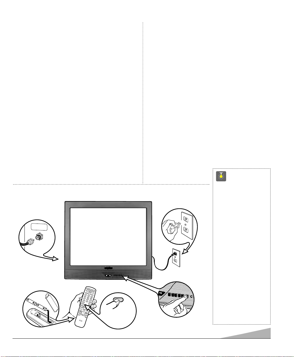
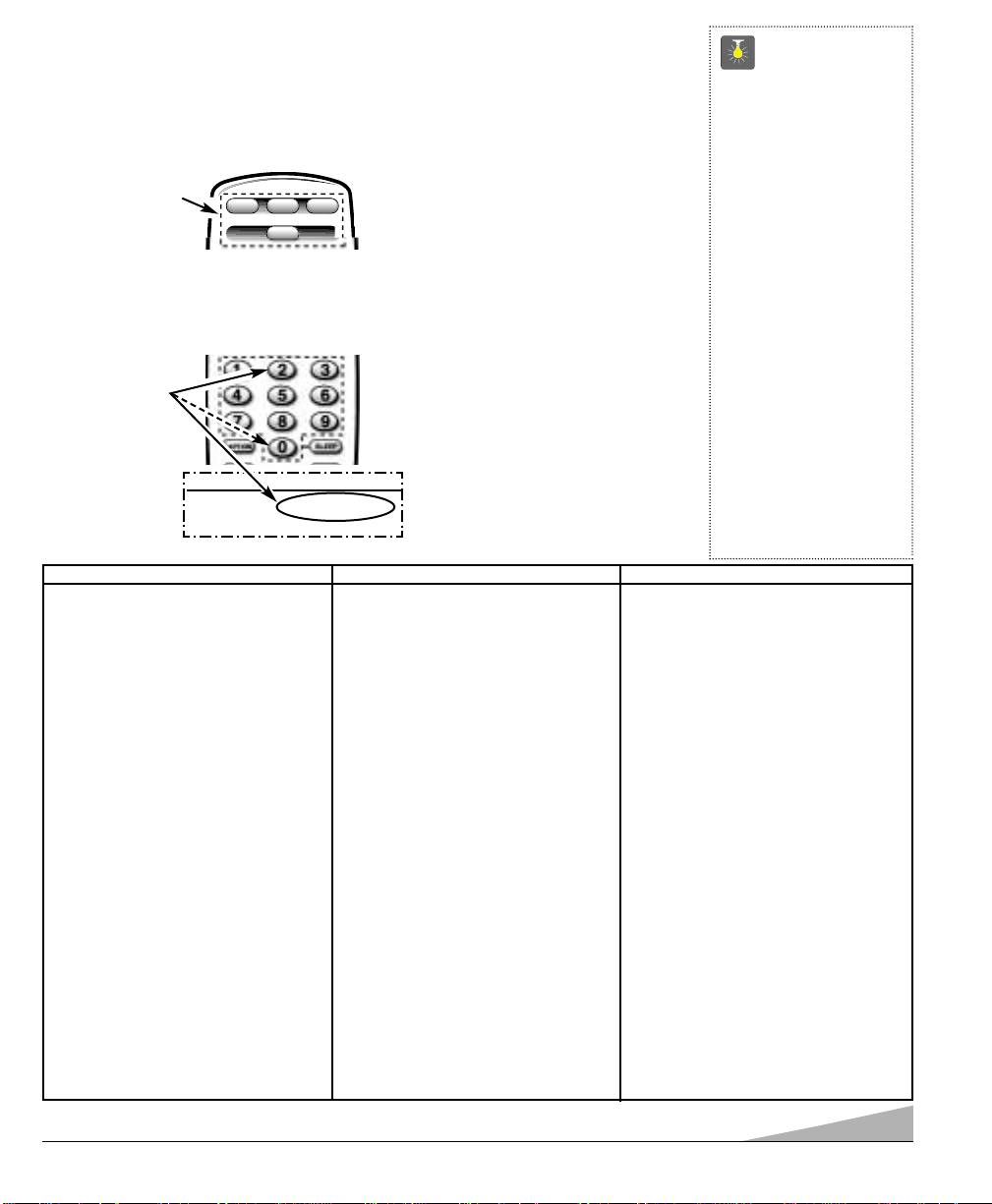
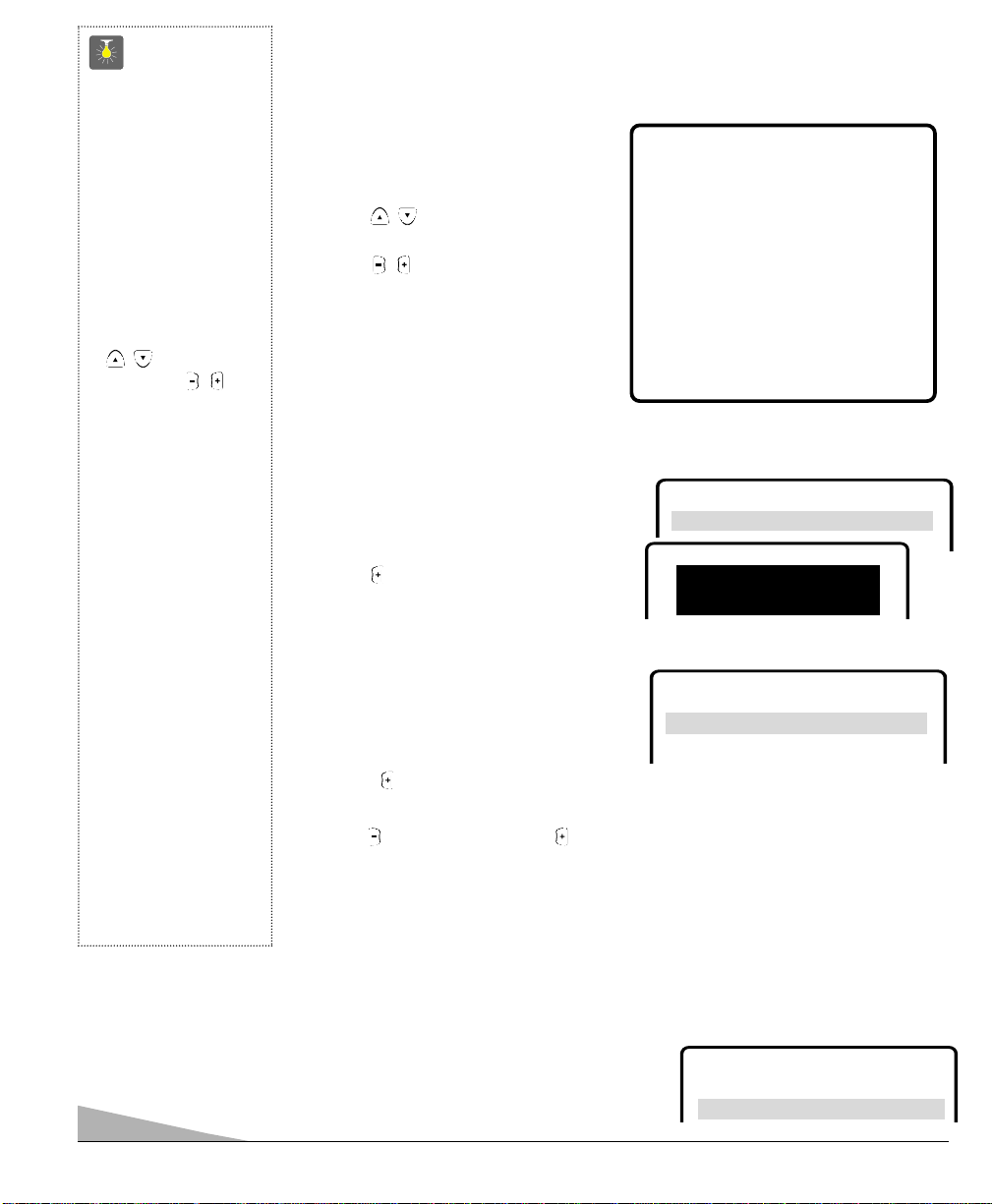
Press button
and hold
down.
QuickTips
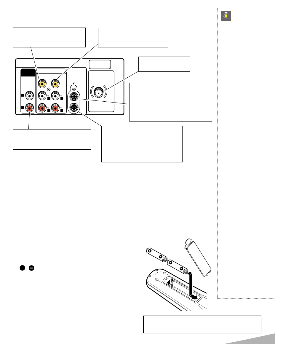
■
The remote control will
not operate my VCR,
DVD, Cable Box, or
Satellite.
– Press the VCR,DVD,
or AUX key.
– Reprogram the
remote control.
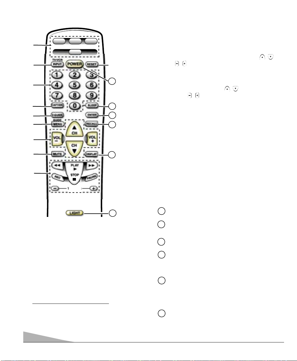
■
Special key functions:
The INPUT/TV•VCR
key functions as the
VCR’s TV/VCR key
when the Remote Con-
trol is in the VCR mode.
■
The AUX mode will
accept codes for DVDs,
Satellite receivers,
Cable boxes, and VCRs,
but only one at a time.
Need help?
Visit our website at
www.sanyoctv.com
or Call 1-800-877-5032
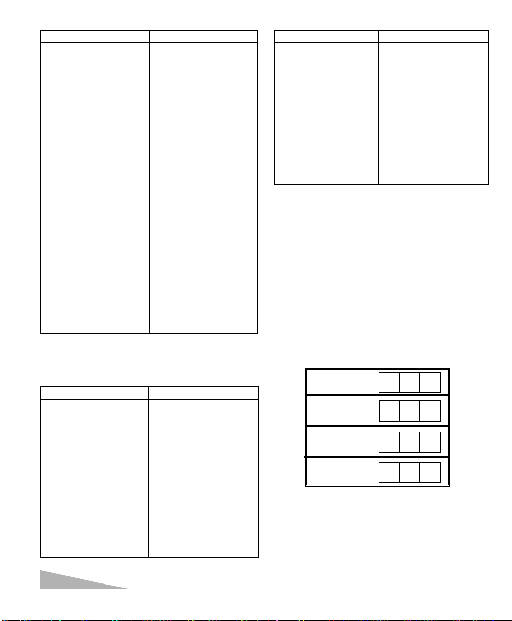
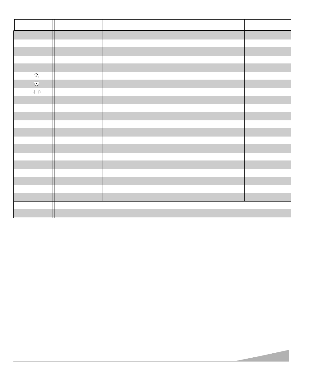
VCR Codes Chart
BRAND NAME CODE NO.
ADMIRAL ................... 234,239,243,247,224,229,222,215
ADVENTURA............... 228
AIKO............................ 240,205
AIWA .......................... 228,217
AKAI ........................... 209,215
AMERICA ACTION....... 205
AMERICA HIGH........... 232
BELL & HOWELL ....... 203
BROKSONIC ............... 234,243,247,227,204
CANDLE ..................... 233,240,222,223,204,205,208
................................... 211,216,217
CANON ....................... 232,216
CCE............................. 240,205
CINERAL..................... 240,205
CITIZEN ...................... 233,240,222,205,211,216,217
CRAIG ........................ 223,202,219
CRAVER...................... 204
CURTIS MATHES ....... 232,236,238,222,228,208,209
................................... 211,216,217
DAEWOO .................... 205,240,211
DAYTRON.................... 240,205
DENON........................ 221
DYNATECH ................. 228
EMEREX...................... 214
EMERSON .................. 234,236,240,243,247,223,227,228
................................... 203,204,205,206,210,211,217
FISHER ....................... 200,201,202,203,211
FUJI............................. 232
FUNAI ......................... 228,233,217
GARRARD................... 228
GE .............................. 222,246,232,236,239,226
................................... 229,224,208,212,216
GOLDSTAR ................ 223,238,226,206,208,215,217
GO VIDEO .................. 248,249,208,212,219
GRADIENTE................. 228
HARLEY DAVIDSON.... 228
HEADQUARTER........... 200
HITACHI ..................... 230,246,226,228,221,222,209,217
BRAND NAME......... CODE NO.
HUGHES...................... 221
JBL ............................. 237
JENSEN....................... 209
JVC ............................ 220,225,238,226,203,209,221
KEC............................. 240,205
KENWOOD ................. 226,238,220,201,203,209
KODAK........................ 232
LLOYD’S...................... 228
LOGIK ........................ 235,219
LXI ............................. 232,221,228,201,202,203,206
................................... 211,217
MAGNASONIC............. 223,240,205,219
MAGNAVOX ............... 204,232,228,211,216,217,219,220
MARTA........................ 206
MATSUSHITA ............. 232,216
MEI.............................. 232
MEMOREX ................. 232,239,243,245,223,224,228,
................................... 229,221,200,202,203,206,215
MINOLTA .................... 221
MITSUBISHI ............... 231,239,244,224,226,229,210,223
MOTOROLA................. 232,239,229,224
MTC ........................... 228,217,219
MULTITECH ............... 228,217
NEC ............................ 238,208,223,226,203,206,209
................................... 215,217
OLYMPUS................... 232
OPRIMUS.................... 239,245,248,223,224,229,203,208
ORION ........................ 243,227,234,205,206,210,211,240
PANASONIC ............... 245,232,236,223,202,211,216,219
PENNY ........................ 230,232,221,223,208,211,216,219
PENTAX ...................... 238,221
PHILCO ...................... 204,232,243,228,216,217
PHILIPS ..................... 204,232,211,216,217,228
PIONEER .................... 242,204,207,220
PROSCAN .................. 222,241,246,230,236,226
PROTON ..................... 219
PULSAR ..................... 233,240,205, 208,216,217
QUARTER.................... 200
BRAND NAME......... CODE NO.
QUARTZ...................... 200
QUASAR ..................... 245,232,236,223,216
RADIO SHACK ............ 228,245,223
RCA ............................ 221,241,246,230,232,236,239,224
................................... 226,229,221,201,207,208,210,216
REALISTIC ................. 232,239,223,224,228,229,200,201
................................... 202,203,206,208,216,217,245
SAMSUNG .................. 208,233,211,217,222
SANKY ........................ 239,229,224
SANSUI ...................... 243,226,228,209,219,220
SANYO ....................... 200,201,202,203
SCOTT ........................ 234,247,223,227,211
SEARS ........................ 232,223,228,221,200,201
,................................. 202,203,206,211,216,217
SEMP.......................... 211
SHARP ....................... 239,229,224
SHINTOM ................... 219,227
SIGNATURE ............... 217,239,229,224,200
SONY ......................... 214,218,232,237,226,228
STS............................. 221
SYLVANIA .................. 228,232,244,204,216,217
SYMPHONIC .............. 217,228,233,226,202
TATUNG ..................... 226,209
TEAC .......................... 228,209,214,217
TECHNICS................... 232
TEKNIKA .................... 232,223,228,216,217
TOMAS ....................... 228,217
TOSHIBA .................... 211,240,244,202,205,210
VECTOR ...................... 211
VIDEO CONCEPT......... 211
WARDS ...................... 230,232,239,223,224,228,229
................................... 221,202,204,208,211,217
WHITE
WESTINGHOUSE......... 240,243,205
XR-1000...................... 228,232
YAMAHA .................... 238,226
ZENITH ....................... 215,237,243,223,225,228,222