Sanyo DS27910 User manual

AS
FILE NO.
SERVICE MANUAL Remote Control Color
Television DS27910 (U.S.A.)
ORIGINALVERSION
Chassis No. 27910-00
NOTE: Match the Chassis No. on
the unit’s back cover with
the Chassis No. in the
Service Manual.
If the Original Version
Service Manual Chassis
No. does not match the
unit’s, additional Service
Literature is required.You
must refer to “Notices” to the
Original Service Manual
prior to servicing the unit.
Contents
Safety Instructions . . . . . . . . . . . . . . . . . . 2
Service Adjustments. . . . . . . . . . . . . 3 - 10
Service Hints. . . . . . . . . . . . . . . . . . . . . . 10
Mechanical Disassemblies. . . . . . . . . . . 11
Chassis Electrical Parts List . . . . . . 12 - 22
Cabinet Parts List . . . . . . . . . . . . . . . . . . 23
Component and Test Point
Locations . . . . . . . . . . . . . . . . . . . 24 - 27
Schematic Insert . . . . . . . . . . . . . . . 29 - 36
Schematic Notes . . . . . . . . . . . . . . . . . 29
Pin Layouts . . . . . . . . . . . . . . . . . . . . . 25
Capacitor and Resistor Codes . . . . . . 29
Block Diagram. . . . . . . . . . . . . . . 30 - 31
Voltage Charts . . . . . . . . . . . . . . . 30 - 32
Waveforms. . . . . . . . . . . . . . . . . . . . . . 32
Schematic Diagrams . . . . . . . . . . 33 - 36
Specifications
Power Rating . . . . . . . . . . . . . . . . . . . . . 120V, 60Hz
112W (Avg), 2.5A (Max)
Antenna Input Impedance . . . . . . . . . . . . . . . . 75W
UHF/VHF/CATV
Receiving Channel . . . . . . . . . . . . . . . . 2 - 13 (VHF),
14 - 69 (UHF),
01, 14-94, 95-125 (CATV)
Remote Ready . . . . . . . . . . 38 Key Remote Control
Sound Output . . . . . . . . . . . . . . . . . . . . . . 3.0 W/CH
Intermediate Frequency
Picture IF Carrier. . . . . . . . . . . . . . . . . . 45.75MHz
Sound IF Carrier . . . . . . . . . . . . . . . . . . 41.25MHz
Color Sub Carrier . . . . . . . . . . . . . . . . . 42.17MHz
Picture Tube . . . . . . . . . . . . . . . . . . A68ERF031X013
Semiconductors
Integrated Circuits. . . . . . . . . . . . . . . . . . . . . . . 12
Transistors. . . . . . . . . . . . . . . . . . . . . . . . . . . . . 45
Except within Tuner and RC Pre-Amp.
Cabinet Dimensions
Width. . . . . . . . . . . . . . . . . . . . . . . . . . . . . 664mm
Height . . . . . . . . . . . . . . . . . . . . . . . . . . . . 629mm
Depth. . . . . . . . . . . . . . . . . . . . . . . . . . . . . 487mm
REFERENCE No. SM780074
DS27910, G7YAM, PRODUCT CODE 111357080
AS
MENU CH VOL VOL POWER
CH
+
_

— 2 —
SAFETY PRECAUTIONS
WARNING: The chassis of this receiver has a floating
ground with the potential of one half the AC line voltage in
respect to earth ground. Service should not be attempted by
anyone not familiar with the precautions necessary when
working on this type of equipment.
The following precautions must be observed:
1. An isolation transformer must be connected in the power
line between the receiver and the AC line before any ser-
vice is performed on the receiver.
2. Comply with all caution and safety-related notes provided
on the side of the cabinet, inside the cabinet, on the chas-
sis, and the picture tube.
3. When replacing a chassis in the cabinet, always be certain
that all the protective devices are installed properly, such
as control knobs, adjustment covers, shields and barriers.
DO NOT OPERATE THIS TELEVISION RECEIVER
WITHOUT THE PROTECTIVE SHIELD IN POSITION AND
PROPERLY SECURED.
4. Before replacing the back cover of the set, thoroughly
inspect the inside of the cabinet to see that no stray parts
or tools have been left inside.
Before returning any television to the customer, the
service technician must perform the following safety
checks to be sure that the unit is completely safe to
operate without danger of electrical shock.
ANTENNA COLD CHECK
Remove AC plug from the 120 VAC outlet and place a
jumper across the two blades. Connect one lead of an ohm-
meter to the jumpered AC plug, and touch the other lead to
each exposed antenna terminal (UHF and VHF antenna ter-
minals). The resistance must measure between 1M ohm and
5.2M ohm. Any resistance value below or above this range
indicates an abnormality which requires corrective action.
LEAKAGE CURRENT CHECK
Plug the AC line cord directly into a 120 VAC outlet. (Do not
use an isolation transformer for this check.) Use an AC volt-
meter, that has 5000 ohms per volt or more sensitivity.
Connect a 1500 ohm 10 watt resistor, paralleled by a 0.15 µF
150 VAC capacitor, between a known good earth ground
(water pipe, conduit, etc.) and all exposed metal parts of the
cabinet (antennas, handle bracket, metal cabinet, screw
heads, metal overlays, control shafts, etc.). Measure the AC
voltage across the 1500 ohm resistor. The AC voltage
should not exceed 750 mV. A reading exceeding 750 mV
indicates that a dangerous potential exists. The fault must
be located and corrected. Repeat the above test with the
receiver power plug reversed.
NEVER RETURN A RECEIVER TO THE CUSTOMER
WITHOUT TAKING THE NECESSARY CORRECTIVE ACTION.
X-RADIATION PRECAUTION
The primary source of X-RADIATION in solid-state receivers is
the picture tube. The picture tube is specially constructed to
limit X-Ray emission. For continued X-RADIATION protection,
the replacement tube must be the same type as the original
(including the suffix letter in the part numbers). Excessive high
voltage may produce potentially hazardous X-RADIATION. To
avoid such hazards, the high voltage must be maintained within
specific limits. Refer to the X-RADIATION WARNING NOTE on
the CHASSIS SCHEMATIC in this service manual for specific
high voltage limits. If the high voltage exceeds specified limits,
check the components specified on the chassis schematic
diagram and take the necessary corrective action. Carefully
follow the instructions for the +B Voltage Check and the High
Voltage Check to maintain the high voltage within the specified
limits.
HIGHVOLTAGE HOLD-DOWNTEST
To prevent X-RADIATION from the picture tube due to
excessive high voltage, a HOLD-DOWN circuit is provided in
the high voltage circuit. Every time the receiver is serviced,
the high voltage HOLD-DOWN circuit must be tested for
proper operation. Refer to the HIGH VOLTAGE HOLD-
DOWN TEST in service adjustments.
PRODUCT SAFETY NOTICE
When replacing components in a receiver, always keep in
mind the necessary product safety precautions. Pay special
attention to the replacement of components marked with a
star (★) in the parts list and in the schematic diagrams. To
ensure safe product operation, it is necessary to replace
those components with the exact same PARTS.
SAFETY INSTRUCTIONS
0.15 µF 150V AC
1500 ohm
10 watt
Good earth ground
such as a water pipe,
conduit, etc.
AC OUTLET
TELEVISION
RECEIVER
READING SHOULD NOT EXCEED 750 mV.
AC VOLTMETER
(5000 ohms per volt or more sensitivity)
To be touched to all of exposed metal parts.
Voltmeter Hook-up for Leakage Current Check.

GENERAL
Thisset has an On-screen Service Menu systemincluded in the CPU that allows remoteoperation for most of the service adjustments.
ON-SCREEN SERVICE MENU SYSTEM
1. Enter the Service Menu:
•While pressing the MENU key, reconnect the AC power cord. The Service Menu Display will now appear. (See Figure 1.)
2. Service Adjustments:
•Press the ▲or ▼key to select the desired service menu you want to adjust. (See page 4 for On-screen Service Menu.)
•Use the + or – key to adjust the data.
3. Exit from the Service Menu:
•Press the MENU key to turn off the Service Menu display.
SERVICE ADJUSTMENTS
— 3 —
IC802 (EEPROM) REPLACEMENT
When IC802 (EEPROM) is replaced, IC801 (CPU) will automatically write the initial reference data into IC802 for basic TV operation.
However, the bus data should be checked and some bus data should be set up before attempting the service adjustments.
(See pages 4 – 6 for detailed information.)
INITIAL BUS DATA SETUP
Note: When IC802 (EEPROM) is replaced, the following bus data must be set up for proper TV operation before attempt-
ing the service adjustments.
1. Disconnect the AC power cord (AC 120V line).
2. While pressing the MENU key, reconnect the AC power cord. The Service Menu display will now appear.
3. Select NO. 03 HP (H Phase) with ▲or ▼key. Adjust the data with + or – key for 12.
4. Select NO. 04 VS (V Size) with ▲or ▼key. Adjust the data with + or – key for 66.
5. Select NO. 05 VPO (V Position) with ▲or ▼key. Adjust the data with + or – key for 45.
6. Select NO. 11 HBR (H BLK R) with ▲or ▼key. Adjust the data with + or – key for 4.
7. Select NO. 19 GD (Green Drive) with ▲or ▼key. Adjust the data with + or – key for 12.
8. Select NO. 23 POS (Pre/Over/SW) with ▲or ▼key. Adjust the data with + or – key for 1.
9. Select NO. 29 WP (White Peak Limiter) with ▲or ▼key. Adjust the data with + or – key for 1.
10. Select NO. 34 DCR (DC Reset) with ▲or ▼key. Adjust the data with + or – key for 1.
11. Select NO. 35 YGM (Y Gamma) with ▲or ▼key. Adjust the data with + or – key for 2.
12. Select NO. 37 AF (Auto Flesh) with ▲or ▼key. Adjust the data with + or – key for 1.
13. Select NO. 41 RYA (R-Y/B-Y Angle) with ▲or ▼key. Adjust the data with + or – key for 2.
14. Select NO. 47 EWD (EW DC) with ▲or ▼key. Adjust the data with + or – key for 46.
15. Select NO. 48 EWA (EW Amp) with ▲or ▼key. Adjust the data with + or – key for 22.
16. Select NO. 49 EWT (EW Tilt) with ▲or ▼key. Adjust the data with + or – key for 36.
17. Select NO. 50 EWP (EW Corner Top) with ▲or ▼key. Adjust the data with + or – key for 5.
18. Select NO. 51 EWB (EW Corner Bottom) with ▲or ▼key. Adjust the data with + or – key for 7.
19. Select NO. 52 HSC (Horz Size Comp) with ▲or ▼key. Adjust the data with + or – key for 6.
20. Select NO. 57 OPT (SA Option ) with ▲or ▼key. Adjust the data with + or – key for 88.
21. Select NO. 58 OP2 (SA Option 2) with ▲or ▼key. Adjust the data with + or – key for 46.
22. Select NO. 60 ATT (Input Level) with ▲or ▼key. Adjust the data with + or – key for 9.
23. Select NO. 63 SBO (Sub Bright Offset) with ▲or ▼key. Adjust the data with + or – key for 2.
24. Press the MENU key to turn off the Service Menu display.
NO. DATA
XX OPT XXX XXXXXXXX
Figure 1. Service Menu Display
ITEM NO.
TITLE BINARY DATA
(8 bit)
DECIMAL DATA

— 4 —
Table 1. ON-SCREEN SERVICE MENU
When IC802 (EEPROM) is replaced, check the bus data to confirm they are the same as below. The shaded menu should be
checked and be set up or readjusted according to the procedures described in the following pages. Initial Setup Data marked
with an * should be changed from Initial Reference Data. (See page 3 for Initial Bus Data Setup.)
NO. TITLE INITIAL REFERENCE INITIAL SETUP RANGE OF DATA FUNCTION
DATA DATA
01 HFR 29 29 0~63 Horizontal Frequency
02 AFC 0 0 0, 1 AFC Gain & Gate
03 HP 11 12* 0~31 Horizontal Phase (Horizontal Centering)
04 VS 64 66* 0~127 Vertical Size
05 VPO 32 45* 0~63 Vertical Position
06 VSP 0 0 0, 1 Vertical Set Up (Sync Sensitivity)
07 VLN 17 17 0~31 Vertical Linearity
08 CRS 0 0 0~3 Cross B/W
09 GRY 1 1 0, 1 Gray Mode
10 VSC 10 10 0~31 Vertical S Correction
11 HBR 3 4* 0~7 H BLK R
12 HBL 4 4 0~7 H BLK L
13 CDM 0 0 0, 1 C D Mode
14 VC 5 5 0~7 Vertical Compression
15 RB 0 0 0~255 Red Bias
16 GB 0 0 0~255 Green Bias
17 BB 0 0 0~255 Blue Bias
18 RD 64 64 0~127 Red Drive
19 GD 8 12* 0~15 Green Drive
20 BD 64 64 0~127 Blue Drive
21 SBI 64 64 0~127 Sub Bias
22 OSD 2 2 0~3 OSD Contrast
23 POS 0 1* 0, 1 Pre/Over/SW
24 FLS 2 2 0~7 Filter System
25 CKO 3 3 0~7 Color Killer Operation
26 GYA 0 0 0, 1 G-Y Angle
27 CRG 2 2 0~3 Coring Gain
28 PRE 1 1 0~3 Pre Shoot Adjust
29 WP 0 1* 0, 1 White Peak Limiter
30 FSW 0 0 0, 1 FBP Blanking Switch
31 VBL 0 0 0, 1 Vertical Blanking Switch
32 BSG 1 1 0~3 Black Str Gain
33 BSS 1 1 0~3 Black Str Start
34 DCR 0 1* 0~3 DC Reset
35 YGM 1 2* 0~3 Y Gamma
36 CBP 0 0 0, 1 C Bypass
37 AF 0 1* 0, 1 Auto Flesh
38 BAT 4 4 0~7 Bright ABL Threshold
39 MSD 0 0 0, 1 Mid Stop Def
40 ABL 0 0 0, 1 Auto Bright Limit
41 RYA 4 2* 0~15 R-Y/B-Y Angle
42 RAD 20 20 0~63 RF AGC Delay
43 IAS 0 0 0, 1 IF AGC
44 FMM 0 0 0, 1 FM Mute
45 FL 15 15 0~31 FM Level

— 5 —
Table 1. ON-SCREEN SERVICE MENU (Continued)
When IC802 (EEPROM) is replaced, check the bus data to confirm they are the same as below. The shaded menu should be
checked and be set up or readjusted according to the procedures described in the following pages. Initial Setup Data
marked with an * should be changed from Initial Reference Data. (See page 3 for Initial Bus Data Setup.)
NO. TITLE INITIAL REFERENCE INITIAL SETUP RANGE OF DATA FUNCTION
DATA DATA
46 VL 4 4 0~7 Video Level
47 EWD 39 46* 0~63 EW DC
48 EWA 30 22* 0~63 EW Amp
49 EWT 34 36* 0~63 EW Tilt
50 EWP 7 5* 0~7 EW Corner Top
51 EWB 8 7* EW Corner Bottom
52 HSC 4 6* Horiz Size Comp
53 SB 32 32 0~63 Sub Bright
54 SCO 7 7 0~31 Sub Color
55 STI 20 20 0~31 Sub Tint
56 SSH 12 12 0~31 Sub Sharpness
57 OPT 0 88* 0~255 Option (See Note 1 page 6.)
58 OP2 0 46* 0~255 Option 2 (See Note 2 page 6.)
59 HR 24 24 0~63 OSD Horizontal Position
60 ATT 10 9* 0~63 Input Level
61 WDB 32 32 0~63 Wideband
62 SPC 32 32 0~63 Spectral
63 SBO 5 2* 0~255 Sub Bright Offset
64 PCO 40 40 0~63 PIP Color
65 PTI 40 40 0~63 PIP Tint
66 PUV 24 24 0~63 PIP Top Position
67 PDV 147 147 0~255 PIP Bottom Position
68 PLH 10 10 0~63 PIP Left Position
69 PRH 101 101 0~255 PIP Right Position
70 PCN 42 42 0~63 PIP Y Level
71 PBS 15 15 0~63 PIP BGP Phase
72 DRV 64 64 0~127 Red Drive Adjustment (See Note 3 page 6.)
64 64 0~127 Blue Drive Adjustment (See Note 3 page 6.)
– 0 0 0~255 Red Bias Adjustment (See Note 4 page 6.)
73 – 0 0 0~255 Green Bias Adjustment (See Note 4 page 6.)
– 0 0 0~255 Blue Bias Adjustment (See Note 4 page 6.)

— 6 —
SERVICE ADJUSTMENTS (Continued)
PROGRAM CODES
The microprossesor used in this model is a multi-purpose
type and is used in several different models. To ensure
proper operation and the correct features for your particu-
lar model, the Program Codes must be correct.
Note 1. Option Data 1 (NO. 57 OPT) should be decimal 88
(01011000 binary). See page 3 INITIAL DATA SETUP, step
20, for set up procedure. If this program code is wrong the
TV will not operate properly.
Note 2. Option Data 2 (NO. 58 OP2) should be decimal 46
(00101110 binary). See page 3 INITIAL DATA SETUP, step
21, for set up procedure. If this program code is wrong the
TV will not operate properly.
DRIVE / BIASADJUSTMENTS
Note 3. Red/Blue Drive Adjustments in Service Menu NO.
72 DRV: Adjust Red and Blue Drive Levels alternately with
1, 3, 7, and 9 keys on the remote control. (See Figure 2.) The
Drive Level adjustment data will be written in the Service
Menu No. 18 and 20 automatically.
123
456
7 98
RB(–) RB(+)
BB(–) BB(+)
(N/A)
GB(–) (N/A) GB(+)
(N/A)
FOR RED BIAS ADJUSTMENT
FOR BLUE BIAS ADJUSTMENT
FOR GREEN BIAS ADJUSTMENT
Figure 2.
Figure 3.
123
4 5 6
7 98
RD(–) RD(+)
BD(–) BD(+)
(N/A)
(N/A) (N/A) (N/A)
(N/A)
FOR RED DRIVE ADJUSTMENT
FOR BLUE DRIVE ADJUSTMENT
BIT FUNCTION DATA
01
0 ~ 2 NOT USED — —
3 CLOCK NONE YES
4 COMB FILTER NONE YES
5 NOT USED — —
00: NONE
6, 7 SURROUND 01: YES
10: —
11: —
Note 4. Red/Green/Blue Bias Adjustments in Service Menu
NO. 73: Adjust each Bias Level with 1, 3, 4, 6, 7, or 9 key on
the remote control. (See Figure 3.) The Bias Level adjust-
ment data will be written in the Service Menu No. 15 ~ 17
automatically.
BIT FUNCTION DATA
01
0SHIPPING CONDITION NORMAL COOL
OF COLOR ENHANCER
1 COLOR ENHANCER NONE YES
2 INITIAL CH & XDS NONE YES
3 AUDIO OUT & SP MENU NONE YES
4 PIP NONE YES
5 AV INPUTS 1 SET 2 SETS
6 BASS & TREBLE / TONE BASS & TR TONE
7 NOT USED ——

— 7 —
ANTENNA CONNECTIONS
This receiver is designed for UHF/VHF reception. A 75 ohm
terminal is provided for UHF and VHF receptions. When
connecting a CATV antenna system, connect the 75 ohm
coaxial cable directly to the 75 ohm terminal. For 300 ohm
VHF antenna, use an adapter (not included with the TV set).
CIRCUIT PROTECTION
Fuse F601 (4A) is included in the AC line. This fuse must be
replaced with the proper fuse (see Parts List).
+BVOLTAGE CHECK
Connect Voltmeter + lead to TJ1 130V and – lead to ground
(TE7). Connect receiver to AC 120V line. Tune receiver to an
active channel. Reset the picture controls to the FACTORY
PRESET levels (press remote control RESET key twice).
Voltage must measure between +133.0V and +137.0V. If the
voltage is out of this range, the power circuit must be
checked. No +B adjustment is provided on this chassis.
HORIZONTALWIDTHADJUSTMENT
1. Tune receiver to an active channel.
2. Check the picture for proper width. If width is not correct,
perform steps 3 ~ 6.
3. Turn off the receiver and disconnect the AC power cord
(120V AC line).
4. While pressing the MENU key, reconnect the AC power
cord. The Service Menu display will now appear.
5. Select NO. 47 EWD (EW DC) with ▲or ▼key.
6. Adjust the data with + or – key for proper width.To turn
off the Service Menu display, press the MENU key.
HORIZONTAL CENTERING ADJUSTMENT
1. Tune receiver to an active channel.
2. Check that picture is in the horizontal center of TV screen.
If picture is not centered horizontally, perform steps 3 ~ 6.
3. Turn off the receiver and disconnect the AC power cord.
4. While pressing the MENU key, reconnect the AC power
cord. The Service Menu display will now appear.
5. Select NO. 03 HP (Horizontal Phase) with ▲or ▼key.
6. Adjust the data with + or – key for horizontal center. To
turn off the Service Menu display, press the MENU key.
VERTICAL SIZEADJUSTMENT
1. Tune receiver to an active channel.
2. Check the vertical size of the picture. If the vertical size is
too large or small, perform steps 3 ~ 6.
3. Turn off the receiver and disconnect the AC power cord.
4. While pressing the MENU key, reconnect the AC power
cord. The Service Menu display will now appear.
5. Select NO. 04 VS (Vertical Size) with ▲or ▼ key.
6. Adjust the data with + or – key for full scan. To turn off
the Service Menu display, press the MENU key.
VERTICAL CENTERINGADJUSTMENT
1. Tune receiver to an active channel.
2. Check that picture is in the center of TV screen. If picture
center is too low, change resistor R513 from 1K ohm 1/2W to
470 ohm 1W. If picture center is too high, remove resistor
R513 (1K ohm, 1/2W).
VCO ADJUSTMENT
Note: VCO must be adjusted after IC101 (Signal Processor),
IC802 (EEPROM) or T151 (VCO Coil) is replaced.
1. Tune receiver to an active channel.
2. Set the picture controls to the Sports level.
3.Connect digital voltmeter + lead to pin 58 of IC101 and
– lead to ground (TE 7).
4. Confirm a reading of 3.6 ± 0.2 VDC.
5.If voltage is out of specifications adjust T151 for
3.6 ± 0.2 VDC.
RFAGCADJUSTMENT
1. Tune receiver to strongest VHF station in your area.
2. Set contrast and brightness controls for maximum.
3. Turn off the receiver and disconnect the AC power cord
(120V AC line).
4. While pressing the MENU key, reconnect the AC power
cord. The Service Menu display will now appear.
5. Select NO. 42 RAD (RF AGC Delay) with ▲or ▼key.
6. Adjust the data with + or – key in the direction which
causes snow to appear; then in the opposite direction
until the snow just disappears.
7.To turn off the Service Menu display, press the MENU key.
VIDEO LEVEL
1. Connect color bar generator to antenna terminals.
2. Turn off the receiver and disconnect the AC power cord
(AC 120V line).
3.Connect oscilloscope to TP16A (Q202 emitter) and ground.
4. While pressing the Menu key, reconnect the AC power
cord. The Service Menu will now appear.
5. Select NO. 46 VL (Video Level) with the ▲or ▼key.
6. Adjust the + or – key for an oscilloscope reading of 1.0 ±
0.1 VP-P at TP16A. Press the MENU key to turn off the
Service Menu display.
CAUTION FOR CONTINUED PROTECTION AGAINST
A RISK OF FIRE, REPLACE ONLY WITH
THE SAME TYPE 4A, 125V FUSE.
ATTENTION : POUR MAINTENIR LA PRO-
TECTION CONTRE LES RISQUES
D’ INCENDIE UTILISER UN FUSIBLE DE
RECHANGE DE MEME TYPE 4A, 125V.
4A 125V
1.0 ± 0.1 VP-P
Figure 4.

SERVICE ADJUSTMENTS (Continued)
— 8 —
GRAYSCALE ADJUSTMENT
1. Set the picture controls to the Sports levels or Reset
(use MENU key and ▲or ▼ key or RESET key).
2. Turn off the receiver and disconnect the AC power cord
(120V AC line).
3. While pressing the MENU key, reconnect the AC power
cord. The Service Menu display will now appear.
4. Select NO. 15 RB (Red Bias), NO. 16 GB (Green Bias),
and NO. 17 BB (Blue Bias) with ▲or ▼ key and set each
data to 0 with + or – key.
5. Select NO. 18 RD (Red Drive) and NO. 20 BD (Blue Drive)
with ▲or ▼key and set each data to 64 with + or – key.
6. Set NO. 19 GD (Green Drive Reduction) data to 8, NO. 53
SB (Sub Brightness) data to 32, NO. 54 SCO (Sub Color)
data to 7, NO. 55 STI (Sub Tint) to 20, and NO. 56 SSH
(Sub Sharpness) data to 12 with ▲or ▼, and + or – keys.
7. Turn Screen Control (T402) to minimum (fully counter-
clockwise).
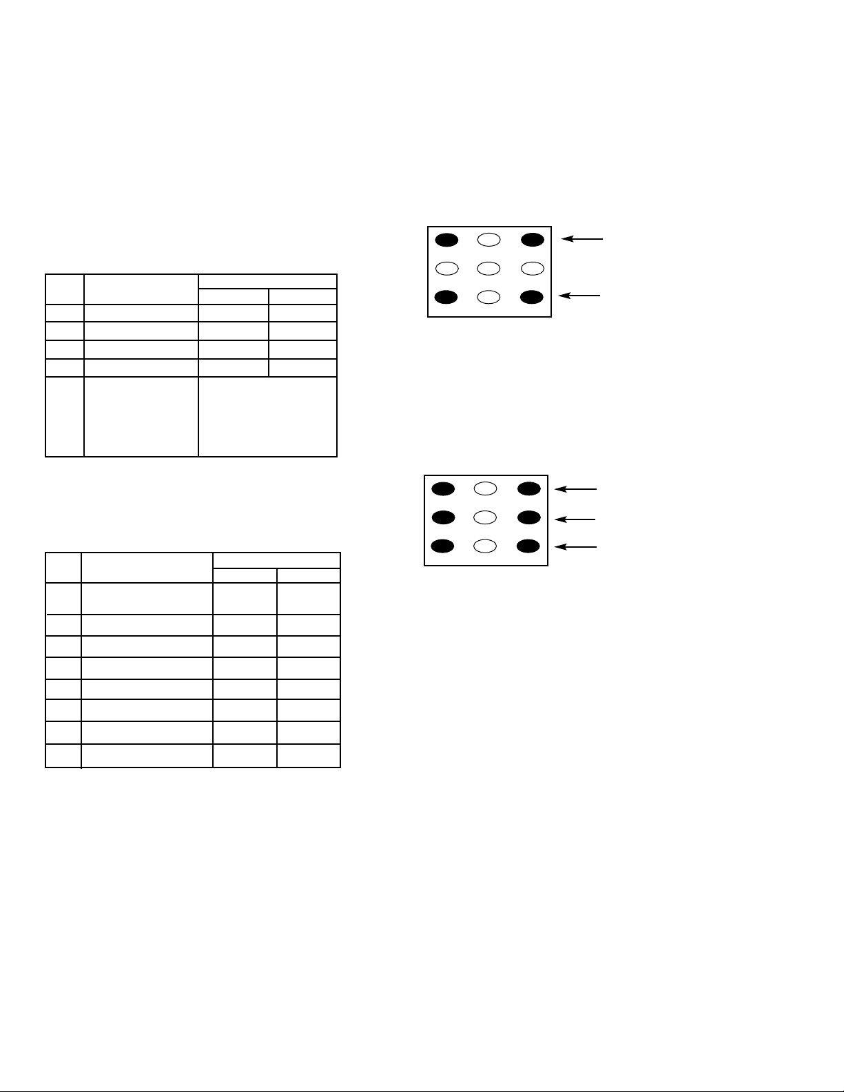
8. Select the Service Menu NO. 73 (Bias Adjustments) with
▲or ▼key.
9. Advance Screen Control (T402) clockwise to obtain just
visible one color line. If line does not appear, place this
control to maximum (fully clockwise).
10. Raise each Bias Level with 3, 6, and 9 keys to obtain just
visible white line. (See Figure 5.)
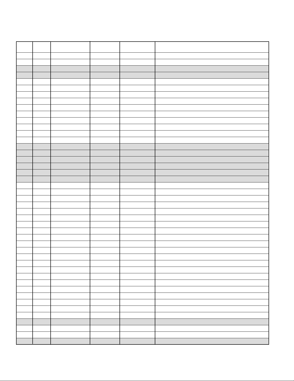
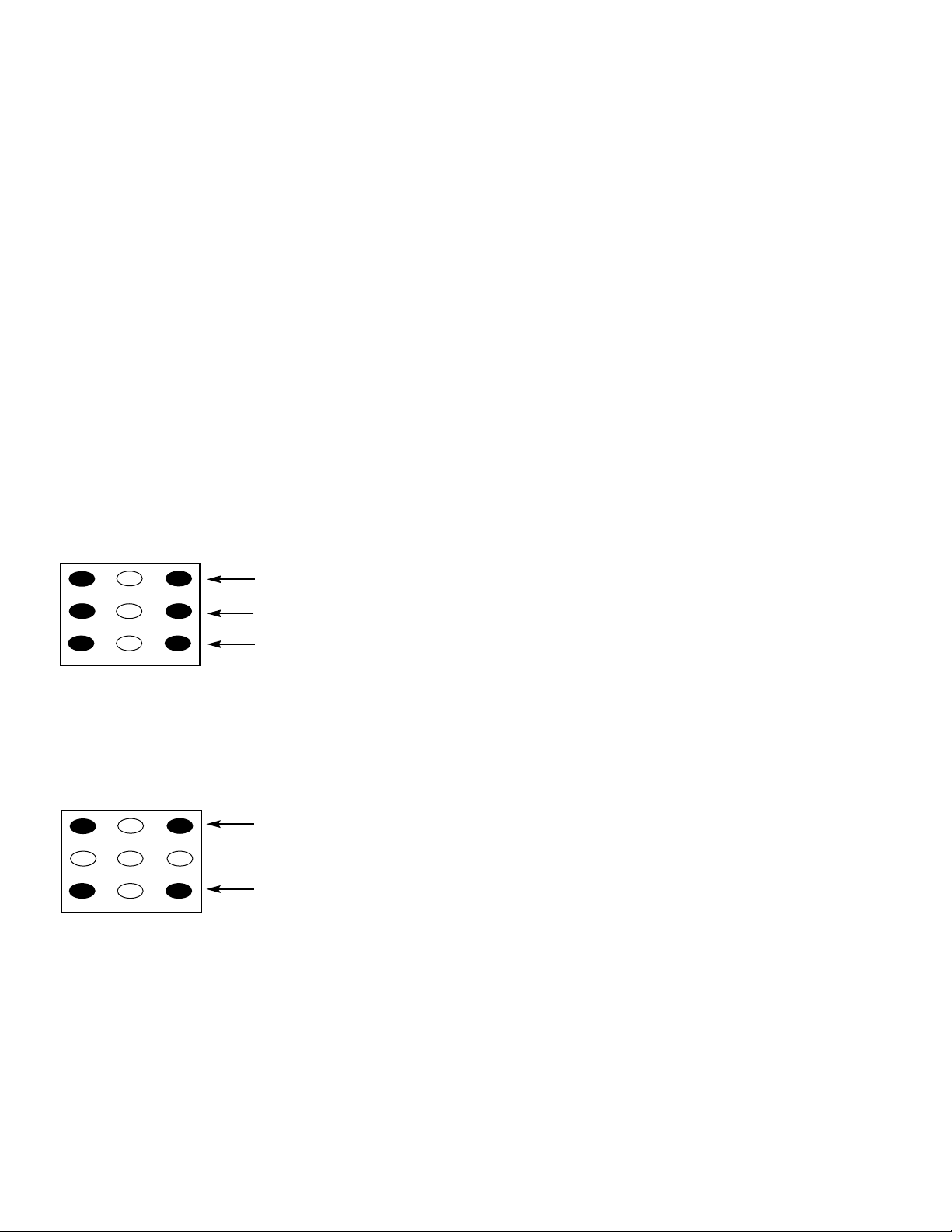
11. Select the Service Menu NO. 72 DRV (Drive Adjustments)
with ▲or ▼key.
12. Adjust Red and Blue Drive Levels alternately with 1, 3,
7, or 9 key to produce normal black and white picture in
highlight areas. (See Figure 6.)
13. Check for proper grayscale at all brightness levels.
To turn off the Service Menu display, press the MENU key.
Note: If Grayscale Adjustment is made after picture tube
replacement, check Brightness Level Adjustment.
BRIGHTNESS LEVELADJUSTMENT
Note: Grayscale, RF AGC, Video Level, and High Voltage Check
must be adjusted before attempting Brightness Level
Adjustment.
1. Connect a color-bar generator to the antenna terminals.
2. Switch the generator to the crosshatch pattern.
3. Reset the picture controls to the Sports levels.
4. Connect voltmeter (high impedance) + lead to terminal
TP51 and – lead to terminal TP50 on main board. Set
voltmeter for 1.5V ~ 3V range.
5. Turn off the receiver and disconnect the AC power cord.
6. While pressing the MENU key, reconnect the AC power
cord. The Service Menu display will now appear.
7. Select NO. 53 SB (Sub Brightness) with ▲or ▼key.
8. Adjust the data with + or – key for 680 mVDC.
9. Press the MENU key to turn off the Service Menu display.
10. Check brightness level on every active channel, readjust
(repeat steps 5 ~ 9), if necessary.
Note: Do not set to excessive brightness level, otherwise
the contrast level will be suppressed.
HIGHVOLTAGE HOLD-DOWNTEST
Every time the receiver is serviced, the HIGH VOLTAGE
HOLD-DOWN circuit must be tested for proper operation by
following these steps:
1. Connect receiver to 120V AC line. Tune receiver to active
channel. Reset the picture controls to the Sports levels.
2.Check that the voltage measured between TP7 and TE7
(ground side) is within 16.5 VDC to 21 VDC. If the voltage
is out of this range, the Hold-Down Circuit must be checked.
3. Connect a DC Voltage supply to TP7 and TE7 through a
100 ohm 1/4W resistor. Adjust the DC voltage to 23 VDC.
The receiver should shutdown, losing raster and sound.
Then the receiver should turn off automatically. This
reaction indicates that the Hold-Down circuit is function-
ing properly. If the receiver does not shutdown, a
malfunction is indicated and its cause must be found and
corrected.
4. To obtain picture again, remove the DC Supply and wait
a few minutes. Now turn on the receiver.
HIGHVOLTAGE CHECK
Note: +B (+130V) Voltage Check and Grayscale Adjustment
must be completed before attempting High Voltage
Check.
1. Connect high voltage voltmeter – lead to ground, and
connect + lead to anode of picture tube.
2. Tune receiver to an active channel and confirm TV is
operating properly.
3. Eliminate the beam current by adjusting the contrast and
brightness controls to minimum.
4. Confirm high voltage is within 28.6 KV and 33.5 KV. If
reading is not within range, check horizontal circuit.
No high-voltage adjustment is provided on this chassis.
123
456
7 98
RB(–) RB(+)
BB(–) BB(+)
(N/A)
GB(–) (N/A) GB(+)
(N/A)
FOR RED BIAS ADJUSTMENT
FOR BLUE BIAS ADJUSTMENT
FOR GREEN BIAS ADJUSTMENT
Figure 5. Remote Control Number keys’ functions in
Service Menu NO. 73
123
4 5 6
7 98
RD(–) RD(+)
BD(–) BD(+)
(N/A)
(N/A) (N/A) (N/A)
(N/A)
Figure 6. Remote Control Number keys’ functions in
Service Menu NO. 72 DRV
FOR RED DRIVE ADJUSTMENT
FOR BLUE DRIVE ADJUSTMENT

— 9 —
FOCUSADJUSTMENT
1. Connect a color-bar generator to the antenna terminals
and select a crosshatch pattern.
2. Set the picture controls to the Sports levels.
3. Select a vertical line at the center of the screen and
adjust the H focus control for best focus.
4. Select a horizontal line at the top of the screen and
adjust the V focus control for best focus.
5. Repeat steps 3 and 4 for best focus.
SOUNDADJUSTMENT
1. Connect a color-bar generator to the antenna terminals
with audio signal of 1KHz at 100% modulation.
2. Set the picture controls to the Sports levels
3.Connect oscilloscope + lead to TP21 (pin 75 of IC101)
and – lead to ground.
4. Turn off the receiver and disconnect the AC power cord
(AC 120V line).
5. While pressing the Menu key, reconnect the AC power
cord. The Service Menu will now appear.
6. Select NO. 45 FL (FM Level) with the ▲or ▼key.
7. Adjust the data with the + or – key for an oscilloscope
reading of 0.693 ± 10% VP-P at TP21.
8. Press the MENU key to turn off the Service Menu display
and disconnect the oscilloscope from the chassis.
MULTI-SOUND SECTION ADJUSTMENTS
Note: Multi-Sound Section must be adjusted after
IC101 (Signal Processor), IC3401 (MTS Decoder), or
IC802 (EEPROM) is replaced.
INPUT LEVELADJUSTMENT
1. Connect a signal to the antenna terminals with audio of
1 KHZ100% modulation.
2. Turn off the receiver and disconnect the AC power cord
(AC 120V line).
3. Connect voltmeter (RMS) to TP317 and ground.
4. While pressing the Menu key, reconnect the AC power
cord. The Service Menu will now appear.
5. Select NO. 60 ATT (Attenuation) with the ▲or ▼key.
6. Adjust the + or – key for a voltmeter reading of 400 ± 20
mVrms at TP317.
SEPARATION ADJUSTMENT
7. Turn off the receiver and disconnect the AC power cord
(AC 120V line).
8.Connect oscilloscope CH1 to TP317 and CH2 to TP318
and ground.
9. Connect an MTS TV/Stereo generator to antenna terminal.
10. While pressing the Menu key, reconnect the AC power
cord. The Service Menu will now appear.
11. Select pilot, 300Hz audio frequency and Left modulating
signal.
12. Select NO. 61 WDB (Wideband) with the ▲or ▼key.
13. Adjust the + or – key for minimum low frequencies at
TP317. (See Figure 10.)
14. Select 4 KHz audio frequency and Right modulating signal.
15. Select NO. 62 SPC (Spectral) with the ▲or ▼key.
16. Adjust the + or – key for minimum high frequencies at
TP318. (See Figure 10.)
Repeat adjustments (steps 11–16) until no further decreases
in amplitude can be obtained. Press the MENU key to turn
off the Service Menu display.
PURITYAND CONVERGENCEADJUSTMENTS
Purity and Convergence have been aligned at the factory.
No re-alignment is necessary.
Minimize L leakage
Minimize R leakage
4KHz
300Hz
TP317 (R)
TP318 (L)
Figure 10. Separation Adjustments
0.693 ± 10% VP-P
Figure 9.
Focus H
VScreen
Adjust the focus of this line using V focus control.
Adjust the focus of this line using H focus control.
Figure 7. Focus controls location
Figure 8. Focus adjustment

— 10 —
SERVICE HINTS
POWER FAILURE DETECTOR
This unit is equipped with a Power Failure Detector function included in the CPU which checks for an abnormal condition in
the chassis power supplies, including the power supply derived from the Horizontal Output Transformer.
If, while the power is on, a failure is caused by any of the following that results in a low voltage supply, the CPU will turn the
unit off in 1.5 seconds to prevent unnecessary damage:
•Failure within the power supply circuits.
•A short circuit in the load side from the supply.
•Stoppage of the Horizontal Output Oscillator caused by the X-Radiation protection Hold-Down Circuit.
If, while the power is off, the power is switched on and any of these failures remains uncorrected, the CPU will shut off the
power within 3 seconds.
Check the following if the unit is turned off by the power failure detector.
1. Disconnect the AC power cord (120V AC line) for at least 10 seconds.
2. Connect a DC Voltmeter to the following TEST POINTS.
3. Press the Power key and check for the proper voltage supplies.
4. If any of these voltages is low, the power failure detector should turn the unit off within 3 seconds.
5. Check all circuits listed above.
Note: This unit is equipped with a Power Surge Protection feature included in the CPU. If power failure occurs three times
within 15 minutes, the CPU will automatically stop functioning to help prevent secondary damage. (TV will not turn on
by pressing the power key.) To reset the operating programs within the CPU, disconnect the AC power cord for at least
10 seconds.
TJ4 26V
TJ59V
D8015V
D429 Cathode 5V
SERVICE ADJUSTMENTS (Continued)
PINCUSHION CORRECTIONADJUSTMENT
1. Connect a color-bar generator to the antenna terminals
and select a crosshatch pattern.
2. Set the picture controls to the Sports levels.
3. Turn off the receiver and disconnect the AC power cord
(AC 120V line).
4. While pressing the Menu key, reconnect the AC power
cord. The Service Menu will now appear.
5. Select No. 49 EWT with ▲or ▼key and adjust with + or –
key for equal tilt at top and bottom.
6. Select No. 48 EWA with ▲or ▼key and adjust with + or –
key for straight vertical lines at the center.
7. Select No. 50 EWP with ▲or ▼key and adjust with + or –
key for straight vertical lines at the top.
8. Select No. 51 EWB with ▲or ▼key and adjust with + or –
key for straight vertical lines at the bottom.
9. Repeat steps 5 through 8 for best pincushion adjustment.
10. Press the MENU key to turn off the Service Menu display.
Adjust No. 49 EWT for equal tilt:
Ta=Tb, Tc=Td.
Adjust No. 48 EWA for the center
part of the vertical line to be straight.
Adjust No. 50 EWP for straight verti-
cal lines at the top.
Adjust No. 51 EWB for straight verti-
cal lines at the bottom.
Ta Tc
Tb Td
EWP
EWB Figure 11. Pincushion adjust

— 11 —
MECHANICAL DISASSEMBLIES
CABINET BACK REMOVAL
1. Refer to Figure 1, remove 9 screws.
2. Pull off cabinet back and remove.
CHASSIS REMOVAL
1. Remove cabinet back.
2. Discharge the picture tube anode (2nd anode lead) to the
dag coating (picture tube grounding lead).
3. Disconnect degaussing coil socket (KD), picture tube
socket, deflection yoke connector (KX), speakers
connector (KSP), picture tube ground lead, and 2nd
anode lead.
4. Remove chassis completely by sliding it straight back.
PICTURETUBE REMOVAL
CAUTION: Do not disturb the deflection yoke or magnet
assembly on the picture tube neck. Care must be taken to
keep these assemblies intact, unless picture tube is being
replaced. Discharge the picture tube to the coating before
handling the tube.
1. Remove chassis, referring to Chassis Removal instructions.
2. Place cabinet’s front face down on a soft surface.
3. Remove the screw on each corner of the picture tube and
GENTLY lift the picture tube out of the cabinet.
4. Install a replacement picture tube in reverse order.
Properly install the degaussing coil and picture tube
grounding lead on the picture tube. See Figure 2.
Note: If Picture Tube is being replaced, mount the Degaussing
Coil properly on the tube. See Figure 2.
DEGAUSSING
COIL DEGAUSSING
COIL HOLDER
PICTURE TUBE
GROUNDING LEAD
TO PICTURE TUBE
SOCKET BOARD
GROUND
DEGAUSSING COIL
SOCKET
Figure 2. Picture Tube Removal
Figure 1. Cabinet Back Removal

— 12 —
CHASSIS ELECTRICAL PARTS LIST
CAPACITORS
NOTES:
Read description of the Capacitor as follows:
(Example)
CERAMIC 100P K 50V Rated Voltage
Tolerance Symbols:
less than 10PF
A . .Not specified
B . .±0.1PF C . .±0.25PF
D . .±0.5PF F . .±1PF
G . .±2PF R . .+0.25 - 0PF
S . .+0 - 0.25PF E . .+0 - 1PF
more than 10PF
A . .Not specified
B . .±0.1% C . .±0.25%
D . .±0.5% F . .±1%
G . .±2% H . .±3%
J . .±5% K . .±10%
L . .±15% M . .±20%
N . .±30% P . .+100 - 0%
Q . .+30 - 10% T . .+50 - 10%
U . .+75 - 10% V . .+20 - 10%
W .+100 - 10% X . .+40 - 20%
Y . .+150 - 10% Z . .+80 - 20%
Rated Value: P...Pico Farad U...Micro Farad
Material:
CERAMIC . . . . . .Ceramic
MT-PAPER . . . . .Metalized Paper
POLYESTER . . .Polyester
MT-POLYEST . .Metalized Polyester
POLYPRO . . . . .Polypropylene
MT-POLYPRO . .Metalized Polypropylene
COMPO-FILM . .Composite Film
MT-COMPO . . . .Metalized Composite
STYRENE . . . . . .Styrene
TA-SOLID . . . . . .Tantalum Solid
AL-SOLID . . . . . .Aluminum Solid
ELECT . . . . . . . .Electrolytic
NP-ELECT . . . . .Non-Polarized Electrolytic
OS-SOLID . . . . .Aluminum Solid with Organic
Semiconductive Electrolytic
C001 403 049 0008 ELECT 1U M 50V
C002 403 049 0008 ELECT 1U M 50V
C005 403 047 8402 ELECT 0.1U M 50V
C007 403 044 9501 ELECT 100U M 25V
C008 403 224 6009 CERAMIC 4700P K 50V
C009 403 224 6009 CERAMIC 4700P K 50V
C010 403 042 4805 ELECT 1000U M 16V
C011 403 042 4805 ELECT 1000U M 16V
C015 403 045 7803 ELECT 220U M 25V
C017 403 357 9601 CERAMIC 0.1U Z 50V
C101 403 038 6301 ELECT 220U M 6.3V
C103 403 224 6108 CERAMIC 0.01U K 50V
C106 403 050 6600 ELECT 3.3U M 50V
C131 403 049 0008 ELECT 1U M 50V
C133 403 224 6108 CERAMIC 0.01U K 50V
C134 403 224 5705 CERAMIC 1000P K 50V
C136 401 150 6001 MT-GLAZE 0.000 ZA 1/10W
C137 403 364 7508 CERAMIC 10P J 50V
C141 403 224 6108 CERAMIC 0.01U K 50V
C142 403 343 4603 CERAMIC 0.022U K 50V
C143 403 224 6108 CERAMIC 0.01U K 50V
C146 403 224 6108 CERAMIC 0.01U K 50V
C147 403 038 1603 ELECT 100U M 6.3V
C151 403 048 6308 ELECT 0.47U M 50V
C153 403 048 6308 ELECT 0.47U M 50V
C161 403 357 9601 CERAMIC 0.1U Z 50V
C211 403 086 2607 NP-ELECT 1U M 50V
C212 403 049 9803 ELECT 2.2U M 50V
C221 403 086 2607 NP-ELECT 1U M 50V
C251 401 150 6001 MT-GLAZE 0.000 ZA 1/10W
C252 403 062 0504 POLYESTER 0.047U K 50V
403 312 2203 POLYESTER 0.047U K 50V
C253 403 048 6308 ELECT 0.47U M 50V
C256 403 049 0008 ELECT 1U M 50V
C257 403 224 6108 CERAMIC 0.01U K 50V
C258 403 043 9106 ELECT 47U M 16V
C272 403 050 6600 ELECT 3.3U M 50V
CAUTION: To Protect against electrical shock and for continued product safety, refer to SAFETY PRECAUTIONS,
X-RADIATION PRECAUTIONS, HIGH VOLTAGE HOLD-DOWN TEST, and PRODUCT SAFETY NOTICE on Page 2.
Notes: Parts having Location Number are located on the following boards.
Numbers 700 Series . . . . . . . . . . . . . . . . . . . . . . . . . . .On the Picture Tube Socket Board.
Numbers 900 Series . . . . . . . . . . . . . . . . . . . . . . . . . . .Out of Board.
Numbers 1700 Series . . . . . . . . . . . . . . . . . . . . . . . . . .On the Picture Tube Socket Board and Main Board
All Other Numbers . . . . . . . . . . . . . . . . . . . . . . . . . . .On the Main Board and Pincushion Correction Board
PRODUCT SAFETY NOTICE
PRODUCT SAFETY SHOULD BE CONSIDERED WHEN A REPLACEMENT IS MADE IN ANY AREA OF A RECEIVER.
COMPONENTS INDICATED BY A STAR (★) INTHIS PARTS LIST ANDTHE SCHEMATIC DIAGRAM DESIGNATE
COMPONENTS IN WHICH SAFETY CAN BE OF SPECIAL SIGNIFICANCE. IT IS PARTICULARLY RECOMMENDED
THAT ONLY PARTS DESIGNATED ONTHE FOLLOWING PARTS LIST BE USED FOR COMPONENT REPLACEMENT
DESIGNATED BYA STAR. NO DEVIATIONS FROM RESISTANCE,WATTAGE,ANDVOLTAGE RATINGS MAY BE MADE
FOR REPLACEMENT ITEMS DESIGNATED BYA STAR.
Schematic
Location Part No. Description Schematic
Location Part No. Description
Note: Schematic part location numbers may not always match with the part descriptions.
The part descriptions are correct and should be used.

— 13 —
C274 403 041 8804 ELECT 10U M 16V
C281 403 067 6204 MT-COMPO 0.15U J 50V
403 166 8307 MT-POLYEST 0.15U J 63V
C283 403 357 9601 CERAMIC 0.1U Z 50V
C284 403 041 8804 ELECT 10U M 16V
C285 403 224 6108 CERAMIC 0.01U K 50V
C301 403 041 8804 ELECT 10U M 16V
C302 403 041 8804 ELECT 10U M 16V
C303 403 357 9601 CERAMIC 0.1U Z 50V
C306 403 357 9601 CERAMIC 0.1U Z 50V
C311 403 043 9106 ELECT 47U M 16V
C312 403 357 9601 CERAMIC 0.1U Z 50V
C313 403 357 9601 CERAMIC 0.1U Z 50V
C314 403 357 9601 CERAMIC 0.1U Z 50V
C316 403 357 9601 CERAMIC 0.1U Z 50V
C317 403 357 9601 CERAMIC 0.1U Z 50V
C322 403 357 9601 CERAMIC 0.1U Z 50V
C323 403 357 9601 CERAMIC 0.1U Z 50V
C401 403 044 1703 ELECT 470U M 16V
C402 403 224 6108 CERAMIC 0.01U K 50V
C403 403 061 8303 POLYESTER 4700P K 50V
403 312 2005 POLYESTER 4700P K 50V
C405 403 086 2607 NP-ELECT 1U M 50V
C406 403 076 3607 CERAMIC 470P K 500V
C407 403 076 0507 CERAMIC 2200P K 500V
C408 403 103 0005 ELECT 4.7U M 160V
★C411 403 353 4204 MT-POLYPRO 6500P H 1.5K
404 076 5509 MT-POLYPRO 6500P H 1.5K
★C412 403 343 8502 MT-POLYPRO 8600P H 1.5K
404 077 5003 MT-POLYPRO 8600P H 1.5K
★C413 403 083 3201 POLYPRO 0.012U J 400V
★C414 403 084 0308 POLYPRO 0.022U J 630V
★C417 403 346 6822 MT-POLYPRO 0.2U J 250V
★C419 403 158 9107 MT-POLYEST 2.2U K 100V
C421 403 038 6301 ELECT 220U M 6.3V
C422 403 187 9703 MT-POLYEST 2.2U J 250V
C427 403 224 6108 CERAMIC 0.01U K 50V
C431 403 155 9704 NP-ELECT 0.1U M 50V
C432 403 224 5705 CERAMIC 1000P K 50V
C433 403 086 1808 NP-ELECT 0.47U M 50V
C434 403 191 4503 NP-ELECT 0.47U M 160V
C441 403 224 6108 CERAMIC 0.01U K 50V
C445 403 045 5809 ELECT 22U M 25V
404 080 4802 ELECT 22U M 50V
C462 403 235 0607 CERAMIC 100P J 50V
C463 403 058 3403 POLYESTER 0.015U K 50V
403 311 9708 POLYESTER 0.015U K 50V
C464 403 067 6204 MT-COMPO 0.15U J 50V
403 166 8307 MT-POLYEST 0.15U J 63V
C472 403 067 5603 MT-COMPO 0.1U J 50V
403 166 6808 MT-POLYEST 0.1U J 63V
C474 403 180 1605 MT-POLYEST 0.1U K 400V
C475 403 152 4702 NP-ELECT 10U M 16V
C476 403 075 7101 CERAMIC 1000P K 500V
C477 403 346 6921 MT-POLYPRO 0.22U J 250V
404 081 2401 MT-POLYPRO 0.22U M 200V
C479 403 073 8308 CERAMIC 4700P K 50V
C482 403 115 0703 ELECT 47U M 100V
C484 403 051 0607 ELECT 4.7U M 50V
C486 403 076 3607 CERAMIC 470P K 500V
C487 403 052 8503 ELECT 1000U M 35V
C489 403 044 1703 ELECT 470U M 16V
C493 404 056 5307 NP-ELECT 2.2U M 100V
C497 403 038 1603 ELECT 100U M 6.3V
C502 403 053 2104 ELECT 220U M 35V
C503 403 276 0208 ELECT 2.2U K 50V
C504 403 045 9807 ELECT 2200U M 25V
C505 403 067 7805 MT-COMPO 0.47U J 50V
403 166 7706 MT-POLYEST 0.47U J 63V
C506 403 058 9306 POLYESTER 0.018U J 50V
403 059 0104 POLYESTER 0.018U K 50V
403 312 0001 POLYESTER 0.018U J 50V
403 312 0100 POLYESTER 0.018U K 50V
C508 403 030 5104 CERAMIC 68P J 50V
C509 403 067 7805 MT-COMPO 0.47U J 50V
403 166 7706 MT-POLYEST 0.47U J 63V
★C511 403 058 5407 POLYESTER 0.15U K 50V
403 141 5802 POLYESTER 0.15U J 50V
403 274 9302 POLYESTER 0.15U J 50V
403 274 9401 POLYESTER 0.15U K 50V
C516 403 049 4204 ELECT 10U M 50V
★C601 404 066 2204 MT-POLYEST 0.22U M 275V
404 071 2404 MT-POLYEST 0.22U M 250V
C602 403 076 6707 CERAMIC 1000P K 1K
403 076 7120 CERAMIC 1000P M 1K
C603 403 076 6707 CERAMIC 1000P K 1K
403 076 7120 CERAMIC 1000P M 1K
C604 403 076 6707 CERAMIC 1000P K 1K
403 076 7120 CERAMIC 1000P M 1K
★C606 404 008 6604 CERAMIC 1000P K 125V
404 046 5409 CERAMIC 1000P M 125V
404 073 4000 CERAMIC 1000P M 250V
★C608 403 247 5508 CERAMIC 4700P K 1K
403 263 6503 CERAMIC 4700P K 1K
★C609 404 059 6905 ELECT 680U M 200V
404 061 3206 ELECT 680U M 200V
C611 403 058 2604 POLYESTER 0.015U J 50V
403 311 9609 POLYESTER 0.015U J 50V
C612 403 067 6501 MT-COMPO 0.18U J 50V
403 166 8208 MT-POLYEST 0.18U J 63V
C613 403 058 2604 POLYESTER 0.015U J 50V
403 311 9609 POLYESTER 0.015U J 50V
C620 403 214 5203 POLYESTER 0.012U J 50V
403 311 9203 POLYESTER 0.012U J 50V
C622 403 045 1504 ELECT 1000U M 25V
★C625 403 247 5508 CERAMIC 4700P K 1K
403 263 6503 CERAMIC 4700P K 1K
C626 403 134 6403 ELECT 2200U M 16V
C628A 404 037 0703 ELECT 470U M 160V
C629 403 043 0202 ELECT 220U M 16V
C630 403 049 0008 ELECT 1U M 50V
C631 404 008 6604 CERAMIC 1000P K 125V
404 046 5409 CERAMIC 1000P M 125V
404 073 4000 CERAMIC 1000P M 250V
★C632 404 008 6802 CERAMIC 2200P M 125V
404 046 5003 CERAMIC 2200P M 125V
404 073 4604 CERAMIC 2200P M 250V
C634 403 043 9106 ELECT 47U M 16V
C683 403 038 6301 ELECT 220U M 6.3V
C688 403 042 2405 ELECT 100U M 16V
C689 403 357 9601 CERAMIC 0.1U Z 50V
C693 403 047 8402 ELECT 0.1U M 50V
Schematic
Location Part No. Description Schematic
Location Part No. Description

— 14 —
C701 403 074 8901 CERAMIC 680P K 50V
C711 403 074 8901 CERAMIC 680P K 50V
C721 403 074 8901 CERAMIC 680P K 50V
★C742 403 077 2807 CERAMIC 1000P Z 2K
C751 403 047 8402 ELECT 0.1U M 50V
C752 403 049 0008 ELECT 1U M 50V
C792 403 047 3100 ELECT 47U M 25V
C801 403 224 6108 CERAMIC 0.01U K 50V
C806 403 039 3507 ELECT 470U M 6.3V
C808 403 224 5507 CERAMIC 22P J 50V
C809 403 224 5507 CERAMIC 22P J 50V
C811 403 049 0008 ELECT 1U M 50V
C822 403 041 8804 ELECT 10U M 16V
C829 403 049 0008 ELECT 1U M 50V
C835 403 224 6108 CERAMIC 0.01U K 50V
C841 403 357 9601 CERAMIC 0.1U Z 50V
C842 403 357 9601 CERAMIC 0.1U Z 50V
C843 403 357 9601 CERAMIC 0.1U Z 50V
C853 403 047 8402 ELECT 0.1U M 50V
C854 403 235 0706 CERAMIC 120P J 50V
C856 403 049 0008 ELECT 1U M 50V
C857 403 235 1000 CERAMIC 220P J 50V
C858 403 224 5705 CERAMIC 1000P K 50V
C862 403 224 6108 CERAMIC 0.01U K 50V
C1001 403 041 8804 ELECT 10U M 16V
C1002 403 042 7707 ELECT 22U M 16V
C1004 403 224 6108 CERAMIC 0.01U K 50V
C1005 403 224 6108 CERAMIC 0.01U K 50V
C1006 403 041 8804 ELECT 10U M 16V
C1011 403 224 6108 CERAMIC 0.01U K 50V
C1021 403 041 8804 ELECT 10U M 16V
C1022 403 042 7707 ELECT 22U M 16V
C1026 403 041 8804 ELECT 10U M 16V
C1031 403 224 6108 CERAMIC 0.01U K 50V
C1081 403 043 9106 ELECT 47U M 16V
C1201 403 049 0008 ELECT 1U M 50V
C1206 403 043 9106 ELECT 47U M 16V
C1211 403 049 0008 ELECT 1U M 50V
C1701 403 058 3403 POLYESTER 0.015U K 50V
403 311 9708 POLYESTER 0.015U K 50V
C1705 403 042 2405 ELECT 100U M 16V
C1706 403 044 9501 ELECT 100U M 25V
C1707 403 224 6009 CERAMIC 4700P K 50V
C1708 403 235 0706 CERAMIC 120P J 50V
C1709 403 235 0300 CERAMIC 56P J 50V
C1711 403 057 0601 POLYESTER 0.01U K 50V
403 311 8701 POLYESTER 0.01U K 50V
C1712 403 214 5203 POLYESTER 0.012U J 50V
403 311 9203 POLYESTER 0.012U J 50V
C1713 403 074 8901 CERAMIC 680P K 50V
C1714 403 075 4209 CERAMIC 820P K 50V
C1715 403 065 1409 POLYESTER 4700P K 200V
403 101 9208 POLYESTER 4700P K 200V
C1716 403 075 4209 CERAMIC 820P K 50V
C1717 403 061 8303 POLYESTER 4700P K 50V
403 312 2005 POLYESTER 4700P K 50V
C1719 403 055 1006 ELECT 10U M 160V
C1721 403 043 9106 ELECT 47U M 16V
C1722 403 102 9900 ELECT 22U M 160V
C1724 403 072 4400 CERAMIC 270P K 50V
C1726 403 035 8407 CERAMIC 270P K 500V
C1740 403 049 0008 ELECT 1U M 50V
C1748 403 069 8305 CERAMIC 0.01U Z 50V
C1749 403 052 7308 ELECT 100U M 35V
C1902 403 041 8804 ELECT 10U M 16V
C3401 403 047 8402 ELECT 0.1U M 50V
C3404 403 086 0108 NP-ELECT 4.7U M 25V
C3406 403 325 2504 CERAMIC 0.012U K 50V
C3407 403 235 5701 CERAMIC 5600P K 50V
C3408 403 048 6308 ELECT 0.47U M 50V
C3411 403 048 6308 ELECT 0.47U M 50V
C3412 403 043 9106 ELECT 47U M 16V
C3413 403 046 9905 ELECT 4.7U M 25V
C3414 403 042 2405 ELECT 100U M 16V
C3416 403 086 0108 NP-ELECT 4.7U M 25V
C3417 403 046 9905 ELECT 4.7U M 25V
C3418 403 086 0108 NP-ELECT 4.7U M 25V
C3421 403 224 5606 CERAMIC 2700P K 50V
C3422 403 323 3602 CERAMIC 0.047U K 50V
C3423 403 342 9203 TA-SOLID 3.3U K 10V
C3424 403 086 0108 NP-ELECT 4.7U M 25V
C3426 403 299 1820 TA-SOLID 10U K 10V
C3427 403 049 0008 ELECT 1U M 50V
C3431 403 224 6009 CERAMIC 4700P K 50V
C3432 403 047 8402 ELECT 0.1U M 50V
C3433 403 224 6009 CERAMIC 4700P K 50V
C3434 403 343 4603 CERAMIC 0.022U K 50V
C3435 403 046 9905 ELECT 4.7U M 25V
C3436 403 086 0108 NP-ELECT 4.7U M 25V
C3437 403 046 9905 ELECT 4.7U M 25V
C3439 403 086 0108 NP-ELECT 4.7U M 25V
C3442 403 046 9905 ELECT 4.7U M 25V
C3444 403 046 9905 ELECT 4.7U M 25V
C3446 403 046 9905 ELECT 4.7U M 25V
C3448 403 046 9905 ELECT 4.7U M 25V
C8803A 403 271 9701 CERAMIC 3300P K 1K
C8804 403 322 3108 CERAMIC 390P K 1K
J700 403 047 8402 ELECT 0.1U M 50V
DIODES
D101 407 056 2307 ZENER DIODE RD36EB1 (36V)
407 100 0204 ZENER DIODE MTZJ36A (36V)
D277 407 209 1201 ZENER DIODE UDZS6.2B (6.2V)
D278 407 209 1201 ZENER DIODE UDZS6.2B (6.2V)
D279 407 209 1201 ZENER DIODE UDZS6.2B (6.2V)
D351 407 056 8002 ZENER DIODE RD5.1EB2 (5.1V)
407 063 8606 ZENER DIODE MTZJ5.1A (5.1V)
D406 407 006 4108 DIODE ERB44-04
D407 407 095 8001 DIODE ERD07-15L
★D421 407 158 1307 ZENER DIODE HZ11B2L (11V)
★D422 407 158 1307 ZENER DIODE HZ11B2L (11V)
D428 407 054 5706 ZENER DIODE RD15EB1 (15V)
407 099 6904 ZENER DIODE MTZJ15A (15V)
D429 407 013 4306 DIODE 1S2076A
407 013 7109 DIODE 1S2473
408 008 2406 DIODE 1N4148
D433 407 209 1201 ZENER DIODE UDZS6.2B (6.2V)
D445 407 007 7405 DIODE EU1
D446 407 055 1707 ZENER DIODE RD20EB1 (20V)
407 099 7802 ZENER DIODE MTZJ20A (20V)
D462 407 012 4406 DIODE 1SS133
Schematic
Location Part No. Description Schematic
Location Part No. Description

— 15 —
D463 407 012 4406 DIODE 1SS133
D472 407 063 8200 ZENER DIODE MTZJ10A (10V)
D473 407 054 0008 ZENER DIODE RD10EB2 (10V)
407 099 6102 ZENER DIODE MTZJ10B (10V)
D481 407 007 6606 DIODE ES1
407 124 5506 DIODE RMPG06G
407 124 6404 DIODE ERA18-04
D482 407 011 4407 DIODE TVR1G
D483 407 007 6606 DIODE ES1
407 124 5506 DIODE RMPG06G
407 124 6404 DIODE ERA18-04
D486 407 054 0008 ZENER DIODE RD10EB2 (10V)
407 099 6102 ZENER DIODE MTZJ10B (10V)
D487 407 005 8602 DIODE ERA15-02
407 011 3004 DIODE S5277B
407 088 6502 DIODE MPG06D
408 009 9404 DIODE 1N4002ID
D490 407 057 0104 ZENER DIODE RD5.6EB3 (5.6V)
407 063 8903 ZENER DIODE MTZJ5.6C (5.6V)
D501 407 005 8602 DIODE ERA15-02
407 011 3004 DIODE S5277B
407 088 6502 DIODE MPG06D
408 009 9404 DIODE 1N4002ID
D502 407 118 2207 ZENER DIODE 1Z75 (75V)
D503 407 056 2307 ZENER DIODE RD36EB1 (36V)
407 100 0204 ZENER DIODE MTZJ36A (36V)
D508 407 013 4306 DIODE 1S2076A
407 013 7109 DIODE 1S2473
408 008 2406 DIODE 1N4148
★D601 407 124 9801 DIODE RBV-608
D609 407 007 6903 DIODE ES1Z
407 124 5605 DIODE RMPG06D
407 124 6503 DIODE ERA18-02
408 009 9008 DIODE BYD33D
D610 407 013 4306 DIODE 1S2076A
407 013 7109 DIODE 1S2473
408 008 2406 DIODE 1N4148
D611 407 054 3108 ZENER DIODE RD12EB1 (12V)
407 099 6508 ZENER DIODE MTZJ12A (12V)
★D612 407 104 2402 PHOTO COUPLE PC817C
407 106 6101 PHOTO COUPLE PC817D
407 147 5705 PHOTO COUPLE ON3131S
407 175 9904 PHOTO COUPLE TLP621-1-BL
D613 407 013 4306 DIODE 1S2076A
407 013 7109 DIODE 1S2473
408 008 2406 DIODE 1N4148
D614 407 013 4306 DIODE 1S2076A
407 013 7109 DIODE 1S2473
408 008 2406 DIODE 1N4148
★D621 407 106 2806 DIODE RU3YX
★D624 407 129 6706 DIODE RU4YX LF-L1
407 211 6102 DIODE FE301-1L43
★D625A 407 191 3900 DIODE FML-G16S
D627 407 013 4306 DIODE 1S2076A
407 013 7109 DIODE 1S2473
408 008 2406 DIODE 1N4148
D629 407 054 7007 ZENER DIODE RD16EB1 (16V)
407 099 7208 ZENER DIODE MTZJ16A (16V)
D680 407 013 4306 DIODE 1S2076A
407 013 7109 DIODE 1S2473
408 008 2406 DIODE 1N4148
D683 407 013 4306 DIODE 1S2076A
407 013 7109 DIODE 1S2473
408 008 2406 DIODE 1N4148
D687 407 013 4306 DIODE 1S2076A
407 013 7109 DIODE 1S2473
408 008 2406 DIODE 1N4148
D693 407 057 2702 ZENER DIODE RD6.2EB2 (6.2V)
407 099 5402 ZENER DIODE MTZJ6.2B (6.2V)
D694 407 013 4306 DIODE 1S2076A
407 013 7109 DIODE 1S2473
408 008 2406 DIODE 1N4148
D702 407 055 1806 ZENER DIODE RD20EB2 (20V)
407 099 7901 ZENER DIODE MTZJ20B (20V)
D712 407 055 1806 ZENER DIODE RD20EB2 (20V)
407 099 7901 ZENER DIODE MTZJ20B (20V)
D722 407 055 1806 ZENER DIODE RD20EB2 (20V)
407 099 7901 ZENER DIODE MTZJ20B (20V)
D751 407 013 4306 DIODE 1S2076A
407 013 7109 DIODE 1S2473
408 008 2406 DIODE 1N4148
D752 407 013 4306 DIODE 1S2076A
407 013 7109 DIODE 1S2473
408 008 2406 DIODE 1N4148
D753 407 013 4306 DIODE 1S2076A
407 013 7109 DIODE 1S2473
408 008 2406 DIODE 1N4148
D801 407 013 4306 DIODE 1S2076A
407 013 7109 DIODE 1S2473
408 008 2406 DIODE 1N4148
D803 407 209 1201 ZENER DIODE UDZS6.2B (6.2V)
D804 407 209 1201 ZENER DIODE UDZS6.2B 96.2V)
D831 407 222 5903 ZD UDZS-TE-173.6B (3.6V)
D834 407 055 3800 ZENER DIODE RD24EB2 (24V)
407 099 8700 ZENER DIODE MTZJ24B (24V)
D836 407 013 4306 DIODE 1S2076A
407 013 7109 DIODE 1S2473
408 008 2406 DIODE 1N4148
D843 407 013 4306 DIODE 1S2076A
407 013 7109 DIODE 1S2473
408 008 2406 DIODE 1N4148
D1001 407 054 0008 ZENER DIODE RD10EB2 (10V)
407 099 6102 ZENER DIODE MTZJ10B (10V)
D1002 407 054 0008 ZENER DIODE RD10EB2 (10V)
407 099 6102 ZENER DIODE MTZJ10B (10V)
D1006 407 054 0008 ZENER DIODE RD10EB2 (10V)
407 099 6102 ZENER DIODE MTZJ10B (10V)
D1011 407 054 0008 ZENER DIODE RD10EB2 (10V)
407 099 6102 ZENER DIODE MTZJ10B (10V)
D1021 407 054 0008 ZENER DIODE RD10EB2 (10V)
407 099 6102 ZENER DIODE MTZJ10B (10V)
D1022 407 054 0008 ZENER DIODE RD10EB2 (10V)
407 099 6102 ZENER DIODE MTZJ10B (10V)
D1026 407 054 0008 ZENER DIODE RD10EB2 (10V)
407 099 6102 ZENER DIODE MTZJ10B (10V)
D1031 407 054 0008 ZENER DIODE RD10EB2 (10V)
407 099 6102 ZENER DIODE MTZJ10B (10V)
D1701 407 011 4308 DIODE TVR1B
D1705 407 108 5300 DIODE SB07-03N
D1707 407 108 5300 DIODE SB07-03N
D1708 407 013 4306 DIODE 1S2076A
407 013 7109 DIODE 1S2473
408 008 2406 DIODE 1N4148
Schematic
Location Part No. Description Schematic
Location Part No. Description

— 16 —
D1901 407 057 6502 ZENER DIODE RD7.5EB3 (7.5V)
407 063 9306 ZENER DIODE MTZJ7.5C (7.5V)
INTEGRATED CIRCUITS
IC001 409 389 4607 IC LA4600
★IC101 409 491 4809 IC LA76834NM-TBM
IC301 409 491 5608 IC TDA9183T/N1
★IC501 409 374 0607 IC LA7846N
★IC601 409 172 8003 IC SE136N
IC681 409 066 7303 IC UPC78L05J
409 241 8309 IC TA78L05S
IC801 410 388 2006 IC M37272M8-XXXFP T4
IC802 409 333 3700 IC 24LC02B/P
409 376 1503 IC ST24C02B6
409 440 8902 IC M24C02-BN6
409 495 6908 IC CAT24WC02P
409 497 0706 IC S524C20D21-DCB0
IC1001 409 051 3006 IC TC4053BP
IC1002 409 051 3006 IC TC4053BP
IC1201 409 051 2930 IC TC4053BF-EL
IC3401 409 467 1108 IC CXA2134Q-T6
COILS
J313 645 008 2894 INDUCTOR, 5.6U K
645 016 3104 INDUCTOR, 5.6U K
J452 645 008 2894 INDUCTOR, 5.6U K
645 016 3104 INDUCTOR, 5.6U K
★LF601 645 012 0589 LINE FILTER
645 026 8274 LINE FILTER
L164 645 003 9713 INDUCTOR, 15U K
645 016 2657 INDUCTOR, 15U K
L301 645 008 2894 INDUCTOR, 5.6U K
645 016 3104 INDUCTOR, 5.6U K
L302 645 008 2894 INDUCTOR, 5.6U K
645 016 3104 INDUCTOR, 5.6U K
L303 645 008 2894 INDUCTOR, 5.6U K
645 016 3104 INDUCTOR, 5.6U K
L401 645 017 7675 INDUCTOR, 3.3U, FILTER
L402 610 031 9998 PIPE CORE
L403 610 078 6820 PIPE CORE
★L413 645 036 7380 COIL, LINEARITY
L414 610 031 1367 INDUCTOR 202J
610 211 3488 INDUCTOR
645 005 5645 INDUCTOR, 2200U K
645 007 8361 INDUCTOR, 2000U
L416 645 016 9120 INDUCTOR, 420UH
645 047 2541 INDUCTOR, 420U
L601 610 078 6820 PIPE CORE
L602 610 078 5946 PIPE CORE
652 000 1725 CORE, PIPE
L603 610 031 9998 PIPE CORE
L621 610 078 5946 PIPE CORE
652 000 1725 CORE, PIPE
L623 610 078 5946 PIPE CORE
652 000 1725 CORE, PIPE
L625 610 078 5946 PIPE CORE
652 000 1725 CORE, PIPE
L628 610 078 5946 PIPE CORE
652 000 1725 CORE, PIPE
L707 610 029 8149 PEAKING COIL 100UH K
645 001 4758 INDUCTOR, 100U K
L717 610 029 8149 PEAKING COIL 100UH K
645 001 4758 INDUCTOR, 100U K
L727 610 029 8149 PEAKING COIL 100UH K
645 001 4758 INDUCTOR, 100U K
L801 645 008 2894 INDUCTOR, 5.6U K
645 016 3104 INDUCTOR, 5.6U K
L851 645 008 2894 INDUCTOR, 5.6U K
645 016 3104 INDUCTOR, 5.6U K
L881 645 006 2490 INDUCTOR, 1U K
645 016 2411 INDUCTOR, 1U K
L882 645 006 2490 INDUCTOR, 1U K
645 016 2411 INDUCTOR, 1U K
★L901 645 048 1635 ASSY, COIL, DEGAUSSING
L1701 610 031 3873 INDUCTOR, 10U K
645 016 2534 INDUCTOR, 10U K
L1702 645 003 9812 INDUCTOR, 33U K
645 016 2985 INDUCTOR, 33U K
L1703 610 078 5946 PIPE CORE
652 000 1725 CORE, PIPE
L1704 610 078 5946 PIPE CORE
652 000 1725 CORE, PIPE
L1705 610 078 5946 PIPE CORE
652 000 1725 CORE, PIPE
L1706 645 008 2894 INDUCTOR, 5.6U K
645 016 3104 INDUCTOR, 5.6U K
L1901 645 008 2894 INDUCTOR, 5.6U K
645 016 3104 INDUCTOR, 5.6U K
TRANSISTORS
Q001 405 011 8401 TR 2SC1740S-Q
405 011 8500 TR 2SC1740S-R
405 011 8609 TR 2SC1740S-S
405 012 2002 TR 2SC1815-GR
405 012 2101 TR 2SC1815-O
405 012 2309 TR 2SC1815-Y
405 020 7501 TR 2SC945A-PA
405 020 7709 TR 2SC945A-QA
405 020 7907 TR 2SC945A-RA
405 151 8705 TR 2SC536NG-NPA
405 157 0505 TR 2SC536NF-NPA
Q135 405 011 8401 TR 2SC1740S-Q
405 011 8500 TR 2SC1740S-R
405 011 8609 TR 2SC1740S-S
405 012 2002 TR 2SC1815-GR
405 012 2101 TR 2SC1815-O
405 012 2309 TR 2SC1815-Y
405 020 7501 TR 2SC945A-PA
405 020 7709 TR 2SC945A-QA
405 020 7907 TR 2SC945A-RA
405 151 8705 TR 2SC536NG-NPA
405 157 0505 TR 2SC536NF-NPA
Q202 405 001 7407 TR 2SA1015-O(SAN)
405 001 7605 TR 2SA1015-Y(SAN)
405 004 3109 TR 2SA564A-Q(CU)
405 004 3208 TR 2SA564A-R(CU)
405 006 1707 TR 2SA933S-Q
405 006 1806 TR 2SA933S-R
405 151 3304 TR 2SA608NF-NPA
406 000 6804 TR 2SA1015-GR(SAN)
Schematic
Location Part No. Description Schematic
Location Part No. Description

— 17 —
Q208 405 001 7407 TR 2SA1015-O(SAN)
405 001 7605 TR 2SA1015-Y(SAN)
405 004 3109 TR 2SA564A-Q(CU)
405 004 3208 TR 2SA564A-R(CU)
405 006 1707 TR 2SA933S-Q
405 006 1806 TR 2SA933S-R
405 151 3304 TR 2SA608NF-NPA
406 000 6804 TR 2SA1015-GR(SAN)
Q401 405 013 6207 TR 2SC2271-D-CTV
405 013 6306 TR 2SC2271-E-CTV
405 029 7106 TR 2SC2271-D
405 029 7205 TR 2SC2271-E
★Q402 405 163 4306 TR 2SD2645-YB
Q451 406 012 1408 TR 2SK2010-CTV-YA14
Q461 405 017 1901 TR 2SC3114-T
405 039 3303 TR 2SC3114-R
405 039 3402 TR 2SC3114-S
Q462 405 064 7307 TR 2SB1274-Q-RA
405 064 7406 TR 2SB1274-R-RA
Q471 406 012 1408 TR 2SK2010-CTV-YA14
Q472 405 011 8401 TR 2SC1740S-Q
405 011 8500 TR 2SC1740S-R
405 011 8609 TR 2SC1740S-S
405 012 2002 TR 2SC1815-GR
405 012 2101 TR 2SC1815-O
405 012 2309 TR 2SC1815-Y
405 020 7501 TR 2SC945A-PA
405 020 7709 TR 2SC945A-QA
405 020 7907 TR 2SC945A-RA
405 151 8705 TR 2SC536NG-NPA
405 157 0505 TR 2SC536NF-NPA
Q486 405 023 5009 TR 2SD400-E-MP
405 023 5306 TR 2SD400-F-MP
Q490 405 023 5009 TR 2SD400-E-MP
405 023 5306 TR 2SD400-F-MP
★Q601 405 080 9002 TR 2SC4424-M
405 080 9101 TR 2SC4424-N
Q604 405 058 0208 TR 2SC3807-R-CTV-YA
Q605 405 001 7407 TR 2SA1015-O(SAN)
405 001 7605 TR 2SA1015-Y(SAN)
405 004 3109 TR 2SA564A-Q(CU)
405 004 3208 TR 2SA564A-R(CU)
405 006 1707 TR 2SA933S-Q
405 006 1806 TR 2SA933S-R
405 151 3304 TR 2SA608NF-NPA
406 000 6804 TR 2SA1015-GR(SAN)
Q627 405 009 6907 TR 2SB985-S
405 009 7003 TR 2SB985-T
405 089 0000 TR 2SA1707-S
405 089 0109 TR 2SA1707-T
Q635 405 011 8401 TR 2SC1740S-Q
405 011 8500 TR 2SC1740S-R
405 011 8609 TR 2SC1740S-S
405 012 2002 TR 2SC1815-GR
405 012 2101 TR 2SC1815-O
405 012 2309 TR 2SC1815-Y
405 020 7501 TR 2SC945A-PA
405 020 7709 TR 2SC945A-QA
405 020 7907 TR 2SC945A-RA
405 151 8705 TR 2SC536NG-NPA
405 157 0505 TR 2SC536NF-NPA
Q681 405 011 8401 TR 2SC1740S-Q
405 011 8500 TR 2SC1740S-R
405 011 8609 TR 2SC1740S-S
405 012 2002 TR 2SC1815-GR
405 012 2101 TR 2SC1815-O
405 012 2309 TR 2SC1815-Y
405 020 7501 TR 2SC945A-PA
405 020 7709 TR 2SC945A-QA
405 020 7907 TR 2SC945A-RA
405 151 8705 TR 2SC536NG-NPA
405 157 0505 TR 2SC536NF-NPA
Q688 405 001 7605 TR 2SA1015-Y(SAN)
405 004 3208 TR 2SA564A-R(CU)
405 006 1806 TR 2SA933S-R
405 151 3304 TR 2SA608NF-NPA
406 000 6804 TR 2SA1015-GR(SAN)
Q693 405 011 8401 TR 2SC1740S-Q
405 011 8500 TR 2SC1740S-R
405 011 8609 TR 2SC1740S-S
405 012 2002 TR 2SC1815-GR
405 012 2101 TR 2SC1815-O
405 012 2309 TR 2SC1815-Y
405 020 7501 TR 2SC945A-PA
405 020 7709 TR 2SC945A-QA
405 020 7907 TR 2SC945A-RA
405 151 8705 TR 2SC536NG-NPA
405 157 0505 TR 2SC536NF-NPA
Q695 405 001 7605 TR 2SA1015-Y(SAN)
405 004 3208 TR 2SA564A-R(CU)
405 004 4809 TR 2SA608-F-CTV-NP
Q701 406 009 9509 TR 2SC4544 LB183
Q702 405 011 8401 TR 2SC1740S-Q
405 011 8500 TR 2SC1740S-R
405 011 8609 TR 2SC1740S-S
405 012 2002 TR 2SC1815-GR
405 012 2101 TR 2SC1815-O
405 012 2309 TR 2SC1815-Y
405 020 7501 TR 2SC945A-PA
405 020 7709 TR 2SC945A-QA
405 020 7907 TR 2SC945A-RA
405 151 8705 TR 2SC536NG-NPA
405 157 0505 TR 2SC536NF-NPA
Q711 406 009 9509 TR 2SC4544 LB183
Q712 405 011 8401 TR 2SC1740S-Q
405 011 8500 TR 2SC1740S-R
405 011 8609 TR 2SC1740S-S
405 012 2002 TR 2SC1815-GR
405 012 2101 TR 2SC1815-O
405 012 2309 TR 2SC1815-Y
405 020 7501 TR 2SC945A-PA
405 020 7709 TR 2SC945A-QA
405 020 7907 TR 2SC945A-RA
405 151 8705 TR 2SC536NG-NPA
405 157 0505 TR 2SC536NF-NPA
Q721 406 009 9509 TR 2SC4544 LB183
Q722 405 011 8401 TR 2SC1740S-Q
405 011 8500 TR 2SC1740S-R
405 011 8609 TR 2SC1740S-S
405 012 2002 TR 2SC1815-GR
405 012 2101 TR 2SC1815-O
405 012 2309 TR 2SC1815-Y
Schematic
Location Part No. Description Schematic
Location Part No. Description

— 18 —
Schematic
Location Part No. Description
Q722 (Cont.)405 020 7501 TR 2SC945A-PA
405 020 7709 TR 2SC945A-QA
405 020 7907 TR 2SC945A-RA
405 151 8705 TR 2SC536NG-NPA
405 157 0505 TR 2SC536NF-NPA
Q751 405 011 8401 TR 2SC1740S-Q
405 011 8500 TR 2SC1740S-R
405 011 8609 TR 2SC1740S-S
405 012 2002 TR 2SC1815-GR
405 012 2101 TR 2SC1815-O
405 012 2309 TR 2SC1815-Y
405 020 7501 TR 2SC945A-PA
405 020 7709 TR 2SC945A-QA
405 020 7907 TR 2SC945A-RA
405 151 8705 TR 2SC536NG-NPA
405 157 0505 TR 2SC536NF-NPA
Q831 405 001 7407 TR 2SA1015-O(SAN)
405 001 7605 TR 2SA1015-Y(SAN)
405 004 3109 TR 2SA564A-Q(CU)
405 004 3208 TR 2SA564A-R(CU)
405 006 1707 TR 2SA933S-Q
405 006 1806 TR 2SA933S-R
405 151 3304 TR 2SA608NF-NPA
406 000 6804 TR 2SA1015-GR(SAN)
Q1201 405 011 8401 TR 2SC1740S-Q
405 011 8500 TR 2SC1740S-R
405 011 8609 TR 2SC1740S-S
405 012 2002 TR 2SC1815-GR
405 012 2101 TR 2SC1815-O
405 012 2309 TR 2SC1815-Y
405 020 7501 TR 2SC945A-PA
405 020 7709 TR 2SC945A-QA
405 020 7907 TR 2SC945A-RA
405 151 8705 TR 2SC536NG-NPA
405 157 0505 TR 2SC536NF-NPA
Q1202 405 011 8401 TR 2SC1740S-Q
405 011 8500 TR 2SC1740S-R
405 011 8609 TR 2SC1740S-S
405 012 2002 TR 2SC1815-GR
405 012 2101 TR 2SC1815-O
405 012 2309 TR 2SC1815-Y
405 020 7501 TR 2SC945A-PA
405 020 7709 TR 2SC945A-QA
405 020 7907 TR 2SC945A-RA
405 151 8705 TR 2SC536NG-NPA
405 157 0505 TR 2SC536NF-NPA
Q1211 405 011 8401 TR 2SC1740S-Q
405 011 8500 TR 2SC1740S-R
405 011 8609 TR 2SC1740S-S
405 012 2002 TR 2SC1815-GR
405 012 2101 TR 2SC1815-O
405 012 2309 TR 2SC1815-Y
405 020 7501 TR 2SC945A-PA
405 020 7709 TR 2SC945A-QA
405 020 7907 TR 2SC945A-RA
405 151 8705 TR 2SC536NG-NPA
405 157 0505 TR 2SC536NF-NPA
Q1212 405 011 8401 TR 2SC1740S-Q
405 011 8500 TR 2SC1740S-R
405 011 8609 TR 2SC1740S-S
405 012 2002 TR 2SC1815-GR
405 012 2101 TR 2SC1815-O
405 012 2309 TR 2SC1815-Y
405 020 7501 TR 2SC945A-PA
405 020 7709 TR 2SC945A-QA
405 020 7907 TR 2SC945A-RA
405 151 8705 TR 2SC536NG-NPA
405 157 0505 TR 2SC536NF-NPA
Q1700 405 001 7407 TR 2SA1015-O(SAN)
405 001 7605 TR 2SA1015-Y(SAN)
405 004 3109 TR 2SA564A-Q(CU)
405 004 3208 TR 2SA564A-R(CU)
405 006 1707 TR 2SA933S-Q
405 006 1806 TR 2SA933S-R
405 151 3304 TR 2SA608NF-NPA
406 000 6804 TR 2SA1015-GR(SAN)
Q1701 405 001 7407 TR 2SA1015-O(SAN)
405 001 7605 TR 2SA1015-Y(SAN)
405 004 3109 TR 2SA564A-Q(CU)
405 004 3208 TR 2SA564A-R(CU)
405 006 1707 TR 2SA933S-Q
405 006 1806 TR 2SA933S-R
405 151 3304 TR 2SA608NF-NPA
406 000 6804 TR 2SA1015-GR(SAN)
Q1702 405 011 8401 TR 2SC1740S-Q
405 011 8500 TR 2SC1740S-R
405 011 8609 TR 2SC1740S-S
405 012 2002 TR 2SC1815-GR
405 012 2101 TR 2SC1815-O
405 012 2309 TR 2SC1815-Y
405 020 7501 TR 2SC945A-PA
405 020 7709 TR 2SC945A-QA
405 020 7907 TR 2SC945A-RA
405 151 8705 TR 2SC536NG-NPA
405 157 0505 TR 2SC536NF-NPA
Q1703 405 011 8609 TR 2SC1740S-S
405 012 2002 TR 2SC1815-GR
405 019 3804 TR 2SC536-G-NP
405 020 7303 TR 2SC945A-KA
Q1705 405 011 8401 TR 2SC1740S-Q
405 011 8500 TR 2SC1740S-R
405 011 8609 TR 2SC1740S-S
405 012 2002 TR 2SC1815-GR
405 012 2101 TR 2SC1815-O
405 012 2309 TR 2SC1815-Y
405 020 7501 TR 2SC945A-PA
405 020 7709 TR 2SC945A-QA
405 020 7907 TR 2SC945A-RA
405 151 8705 TR 2SC536NG-NPA
405 157 0505 TR 2SC536NF-NPA
Q1706 405 011 8401 TR 2SC1740S-Q
405 011 8500 TR 2SC1740S-R
405 011 8609 TR 2SC1740S-S
405 012 2002 TR 2SC1815-GR
405 012 2101 TR 2SC1815-O
405 012 2309 TR 2SC1815-Y
405 020 7501 TR 2SC945A-PA
405 020 7709 TR 2SC945A-QA
405 020 7907 TR 2SC945A-RA
405 151 8705 TR 2SC536NG-NPA
405 157 0505 TR 2SC536NF-NPA
Schematic
Location Part No. Description

— 19 —
Schematic
Location Part No. Description Schematic
Location Part No. Description
Q1707 405 011 8401 TR 2SC1740S-Q
405 011 8500 TR 2SC1740S-R
405 011 8609 TR 2SC1740S-S
405 012 2002 TR 2SC1815-GR
405 012 2101 TR 2SC1815-O
405 012 2309 TR 2SC1815-Y
405 020 7501 TR 2SC945A-PA
405 020 7709 TR 2SC945A-QA
405 020 7907 TR 2SC945A-RA
405 151 8705 TR 2SC536NG-NPA
405 157 0505 TR 2SC536NF-NPA
Q1708 405 001 7407 TR 2SA1015-O(SAN)
405 001 7605 TR 2SA1015-Y(SAN)
405 004 3109 TR 2SA564A-Q(CU)
405 004 3208 TR 2SA564A-R(CU)
405 006 1707 TR 2SA933S-Q
405 006 1806 TR 2SA933S-R
405 151 3304 TR 2SA608NF-NPA
406 000 6804 TR 2SA1015-GR(SAN)
Q1709 405 108 4903 TR 2SA1837-LB
Q1711 405 108 5009 TR 2SC4793-LB
Q1712 405 011 8401 TR 2SC1740S-Q
405 011 8500 TR 2SC1740S-R
405 011 8609 TR 2SC1740S-S
405 012 2002 TR 2SC1815-GR
405 012 2101 TR 2SC1815-O
405 012 2309 TR 2SC1815-Y
405 020 7501 TR 2SC945A-PA
405 020 7709 TR 2SC945A-QA
405 020 7907 TR 2SC945A-RA
405 151 8705 TR 2SC536NG-NPA
405 157 0505 TR 2SC536NF-NPA
R001 401 024 9701 CARBON 12K JA 1/6W
R002 401 024 9701 CARBON 12K JA 1/6W
R003 401 256 3805 MT-GLAZE 1.5K JA 1/10W
R004 401 256 3805 MT-GLAZE 1.5K JA 1/10W
R007 401 162 3708 MT-GLAZE 4.7K JA 1/10W
R008 401 026 9907 CARBON 4.7K JA 1/6W
R011 401 026 3905 CARBON 330 JA 1/6W
R012 401 027 2600 CARBON 5.6K JA 1/6W
★R106 401 067 1700 OXIDE-MT 27K JA 2W
R131 401 256 1702 MT-GLAZE 33K JA 1/10W
R133 401 255 6401 MT-GLAZE 3K JA 1/10W
R135 401 150 6001 MT-GLAZE 0.000 ZA 1/10W
R137 401 162 2800 MT-GLAZE 1.8K JA 1/10W
R142 401 256 1702 MT-GLAZE 33K JA 1/10W
R143 401 150 6209 MT-GLAZE 1K JA 1/10W
R151 401 152 3206 MT-GLAZE 330 JA 1/10W
R161 401 150 5806 MT-GLAZE 100K JA 1/10W
R162 401 150 5806 MT-GLAZE 100K JA 1/10W
R163 401 256 0002 MT-GLAZE 120 JA 1/10W
R164 401 150 6209 MT-GLAZE 1K JA 1/10W
R166 401 256 7506 MT-GLAZE 390 JA 1/10W
R167 401 162 2701 MT-GLAZE 180 JA 1/10W
R201 401 162 3609 MT-GLAZE 470 JA 1/10W
R208 401 150 6209 MT-GLAZE 1K JA 1/10W
R212 401 256 7100 MT-GLAZE 680K JA 1/10W
R251 401 162 3005 MT-GLAZE 22K JA 1/10W
R252 401 162 3005 MT-GLAZE 22K JA 1/10W
R271 401 162 3401 MT-GLAZE 39K JA 1/10W
R272 401 027 5502 CARBON 6.8K JA 1/6W
R273 401 024 7400 CARBON 10K JA 1/6W
R274 401 162 4101 MT-GLAZE 5.6K JA 1/10W
R275 401 256 6608 MT-GLAZE 68K JA 1/10W
R276 401 024 9701 CARBON 12K JA 1/6W
R280 401 026 4902 CARBON 330K JA 1/6W
R281 401 150 5905 MT-GLAZE 10K JA 1/10W
R284 401 026 9303 CARBON 47 JA 1/6W
R287 401 255 6500 MT-GLAZE 100 JA 1/10W
R288 401 255 6500 MT-GLAZE 100 JA 1/10W
R289 401 255 6500 MT-GLAZE 100 JA 1/10W
R301 401 150 6001 MT-GLAZE 0.000 ZA 1/10W
R311 401 024 6700 CARBON 100 JA 1/6W
R312 401 255 6500 MT-GLAZE 100 JA 1/10W
R321 401 150 5905 MT-GLAZE 10K JA 1/10W
R323 401 256 4109 MT-GLAZE 56 JA 1/10W
R324 401 255 6500 MT-GLAZE 100 JA 1/10W
R326 401 256 4109 MT-GLAZE 56 JA 1/10W
R353 401 024 7400 CARBON 10K JA 1/6W
★R401 401 012 4503 CARBON 100 JA 1/4W
★R402 401 013 4205 CARBON 120 JA 1/4W
R404 401 026 3905 CARBON 330 JA 1/6W
R405 401 256 7308 MT-GLAZE 6.8K JA 1/10W
R406 401 010 8305 CARBON 5.6K JA 1/2W
★R407 401 069 3702 OXIDE-MT 6.8K JA 2W
★R408 401 059 4900 OXIDE-MT 15K JA 1W
★R413 402 085 5909 OXIDE-MT 3.9JB 5W
★R414 402 080 3108 OXIDE-MT 4.7 JB 5W
R416 401 018 1605 CARBON 33 JA 1/4W
★R418 401 067 1007 OXIDE-MT 2.7K JA 2W
★R421 401 083 8301 MT-FILM 1.2K FA 1/6W
★R422 401 052 6802 MT-FILM 10K FA 1/6W
★R423 401 089 7605 MT-GLAZE 3.3K FA 1/10W
Tolerance Symbols:
A...0.05% B...0.1% C...25%
D...0.5% F...1% G...2%
J...5% K...10% M...20%
P...+5 -15%
Rated Value, ohms:
K...1,000 M...1,000,000
Material:
CARBON .............
MT-FILM ..............
OXIDE-MT ...........
SOLID ..................
MT-GLAZE ...........
WIRE WOUND .....
CERAMIC RES ....
FUSIBLE RES .....
Performance Symbols:
A...General B...Non-flammable
Z...Low noise
Other...Temperature coefficient
Rated Wattage
CARBON 4.7K J A 1/4W
Read description of the Resistor as follows:
NOTES:
(Example)
Carbon
Metal Film
Oxide Metal Film
Composition
Metal Glaze
Wire Wound
Ceramic
Fusible

— 20 —
Schematic
Location Part No. Description
R426 401 256 6905 MT-GLAZE 680 JA 1/10W
R428 401 025 1902 CARBON 15K JA 1/6W
R431 401 255 9600 MT-GLAZE 820K JA 1/10W
R432 401 255 9600 MT-GLAZE 820K JA 1/10W
R434 401 026 1307 CARBON 27K JA 1/6W
R441 401 024 7004 CARBON 1K JA 1/6W
R442 401 150 5905 MT-GLAZE 10K JA 1/10W
R443 401 025 4606 CARBON 18K JA 1/6W
R444 401 025 4606 CARBON 18K JA 1/6W
★R445 401 062 6106 OXIDE-MT 560 JA 1W
R449 401 053 3206 MT-FILM 4.7K FA 1/6W
R451 401 007 2309 CARBON 100K JA 1/2W
R452 401 027 8602 CARBON 8.2K JA 1/6W
R453 401 024 7004 CARBON 1K JA 1/6W
R455 401 027 2303 CARBON 560 JA 1/6W
★R456 401 066 1404 OXIDE-MT 1.8K JA 2W
★R457 401 066 1404 OXIDE-MT 1.8K JA 2W
★R458 401 068 0207 OXIDE-MT 3.9K JA 2W
★R459 401 068 0207 OXIDE-MT 3.9K JA 2W
R460 401 053 4005 MT-FILM 560 FA 1/6W
R462 401 162 3708 MT-GLAZE 4.7K JA 1/10W
★R463 401 061 0006 OXIDE-MT 3.3 JA 1W
R465 401 258 8006 MT-FILM 120K FA 1/6W
R468 401 027 0309 CARBON 47K JA 1/6W
R469 401 024 7004 CARBON 1K JA 1/6W
R470 401 007 2309 CARBON 100K JA 1/2W
R472 401 027 8305 CARBON 820 JA 1/6W
R473 401 027 2600 CARBON 5.6K JA 1/6W
R474 401 027 0507 CARBON 470K JA 1/6W
★R475 401 062 3006 OXIDE-MT 47K JA 1W
R476 401 026 1000 CARBON 2.7K JA 1/6W
R477 401 024 6700 CARBON 100 JA 1/6W
★R481 401 006 7701 CARBON 1 JB 1/2W
★R482 401 021 0701 CARBON 56 JA 1/4W
★R483 401 006 7701 CARBON 1 JB 1/2W
R485 401 025 4606 CARBON 18K JA 1/6W
★R486 401 069 0404 OXIDE-MT 6.8 JA 2W
R487 401 025 3807 CARBON 180 JA 1/6W
★R488 401 059 1602 OXIDE-MT 15 JA 1W
★R489 401 060 1707 OXIDE-MT 22 JA 1W
R491 401 012 5708 CARBON 1K JA 1/4W
R492 401 156 8504 MT-FILM 33K FA 1/6W
R493 401 017 3808 CARBON 270K JA 1/4W
R494 401 017 3808 CARBON 270K JA 1/4W
★R495 401 061 1706 OXIDE-MT 33 JA 1W
★R497 401 068 6209 OXIDE-MT 5.6 JA 2W
R499 401 026 6609 CARBON 390 JA 1/6W
R503 401 026 9907 CARBON 4.7K JA 1/6W
R504 401 024 7400 CARBON 10K JA 1/6W
R505 401 006 8104 CARBON 1.2 JA 1/2W
R506 401 027 8305 CARBON 820 JA 1/6W
R507 401 006 8104 CARBON 1.2 JA 1/2W
R508 401 025 4606 CARBON 18K JA 1/6W
R509 401 025 4606 CARBON 18K JA 1/6W
★R511 401 067 0000 OXIDE-MT 270 JA 2W
R513 401 062 1200 OXIDE-MT 470 JA 1W
★R516 401 067 0000 OXIDE-MT 270 JA 2W
R517 401 026 4605 CARBON 33K JA 1/6W
R518 401 256 3607 MT-GLAZE 15K JA 1/10W
★R601 402 056 6805 WIRE WOUND 1 KA 10W
402 073 6901 WIRE WOUND 1 KA 10W
★R602 402 000 0705 SOLID 3.3M KA 1/2W
R603 401 007 2309 CARBON 100K JA 1/2W
★R604 401 065 5809 OXIDE-MT 15 JA 2W
★R606 401 065 5809 OXIDE-MT 15 JA 2W
★R613 401 068 6902 OXIDE-MT 56 JA 2W
R614 401 011 1107 CARBON 68 JA 1/2W
R615 401 014 5201 CARBON 15K JA 1/4W
R616 401 025 1506 CARBON 1.5K GA 1/6W
R617 401 024 6908 CARBON 1K GA 1/6W
★R618 401 069 1708 OXIDE-MT 68 JA 2W
R619 401 025 8208 CARBON 22K JA 1/6W
R620 401 027 2600 CARBON 5.6K JA 1/6W
R622 401 025 4200 CARBON 1.8K JA 1/6W
R627 401 024 7400 CARBON 10K JA 1/6W
R628 401 013 5301 CARBON 1.2K JA 1/4W
R629 401 150 6209 MT-GLAZE 1K JA 1/10W
★R630 401 060 5002 OXIDE-MT 22K JA 1W
R631 401 022 3107 CARBON 6.8K JA 1/4W
R632 401 150 6209 MT-GLAZE 1K JA 1/10W
R634 401 256 6301 MT-GLAZE 47K JA 1/10W
R683 401 026 7002 CARBON 3.9K JA 1/6W
R687 401 162 3005 MT-GLAZE 22K JA 1/10W
R688 401 256 0408 MT-GLAZE 12K JA 1/10W
R691 401 024 7400 CARBON 10K JA 1/6W
R692 401 027 5908 CARBON 68K JA 1/6W
R693 401 027 3201 CARBON 560K JA 1/6W
R694 401 024 7400 CARBON 10K JA 1/6W
R695 401 025 8208 CARBON 22K JA 1/6W
R701 401 024 9008 CARBON 120 JA 1/6W
R702 401 024 7004 CARBON 1K JA 1/6W
R703 401 024 7004 CARBON 1K JA 1/6W
R704 401 027 8107 CARBON 82 JA 1/6W
R706 401 009 1508 CARBON 2.7K JA 1/2W
★R707 401 069 8202 OXIDE-MT 8.2K JA 2W
R709 401 027 2303 CARBON 560 JA 1/6W
R711 401 024 9008 CARBON 120 JA 1/6W
R712 401 024 7004 CARBON 1K JA 1/6W
R713 401 024 7004 CARBON 1K JA 1/6W
R714 401 027 8107 CARBON 82 JA 1/6W
R716 401 009 1508 CARBON 2.7K JA 1/2W
★R717 401 069 8202 OXIDE-MT 8.2K JA 2W
R719 401 027 2303 CARBON 560 JA 1/6W
R721 401 024 9008 CARBON 120 JA 1/6W
R722 401 024 7004 CARBON 1K JA 1/6W
R723 401 024 7004 CARBON 1K JA 1/6W
R724 401 027 8107 CARBON 82 JA 1/6W
R726 401 009 1508 CARBON 2.7K JA 1/2W
★R727 401 069 8202 OXIDE-MT 8.2K JA 2W
R729 401 027 2303 CARBON 560 JA 1/6W
R751 401 026 4308 CARBON 3.3K JA 1/6W
R752 401 026 4308 CARBON 3.3K JA 1/6W
R753 401 024 7004 CARBON 1K JA 1/6W
R792 401 008 2605 CARBON 180K JA 1/2W
R793 401 024 9701 CARBON 12K JA 1/6W
R803 401 024 6700 CARBON 100 JA 1/6W
R804 401 024 6700 CARBON 100 JA 1/6W
R806 401 162 3708 MT-GLAZE 4.7K JA 1/10W
R807 401 150 5905 MT-GLAZE 10K JA 1/10W
R808 401 150 5905 MT-GLAZE 10K JA 1/10W
R809 401 162 3708 MT-GLAZE 4.7K JA 1/10W
R811 401 025 1902 CARBON 15K JA 1/6W
Schematic
Location Part No. Description
Other manuals for DS27910
1
Table of contents
Other Sanyo TV manuals

Sanyo
Sanyo CP21YS2 User manual

Sanyo
Sanyo DS19500 User manual

Sanyo
Sanyo 21P1 User manual

Sanyo
Sanyo CP21SE1K User manual

Sanyo
Sanyo CZP3011V User manual

Sanyo
Sanyo CP21FS2 User manual

Sanyo
Sanyo FVM4612 User manual

Sanyo
Sanyo DS25500 User manual

Sanyo
Sanyo DP37819 - 37" Diagonal FULL 1080p LCD HDTV User manual

Sanyo
Sanyo CE19LD90N-B User manual

Sanyo
Sanyo CP14SE1-00 User manual

Sanyo
Sanyo FVE3923 User manual

Sanyo
Sanyo C21LF37 User manual

Sanyo
Sanyo CP14KX2 User manual

Sanyo
Sanyo EP58B Installer manual

Sanyo
Sanyo C25PP86N User manual

Sanyo
Sanyo DP42849 - 42" LCD TV User manual

Sanyo
Sanyo P46841-03 User manual

Sanyo
Sanyo CE21D4-C User manual

Sanyo
Sanyo CE21P1-C User manual