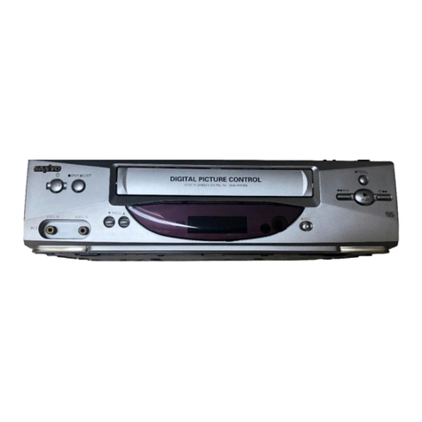
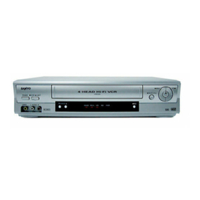
Sanyo VHR-690 User manual

FILE NO.
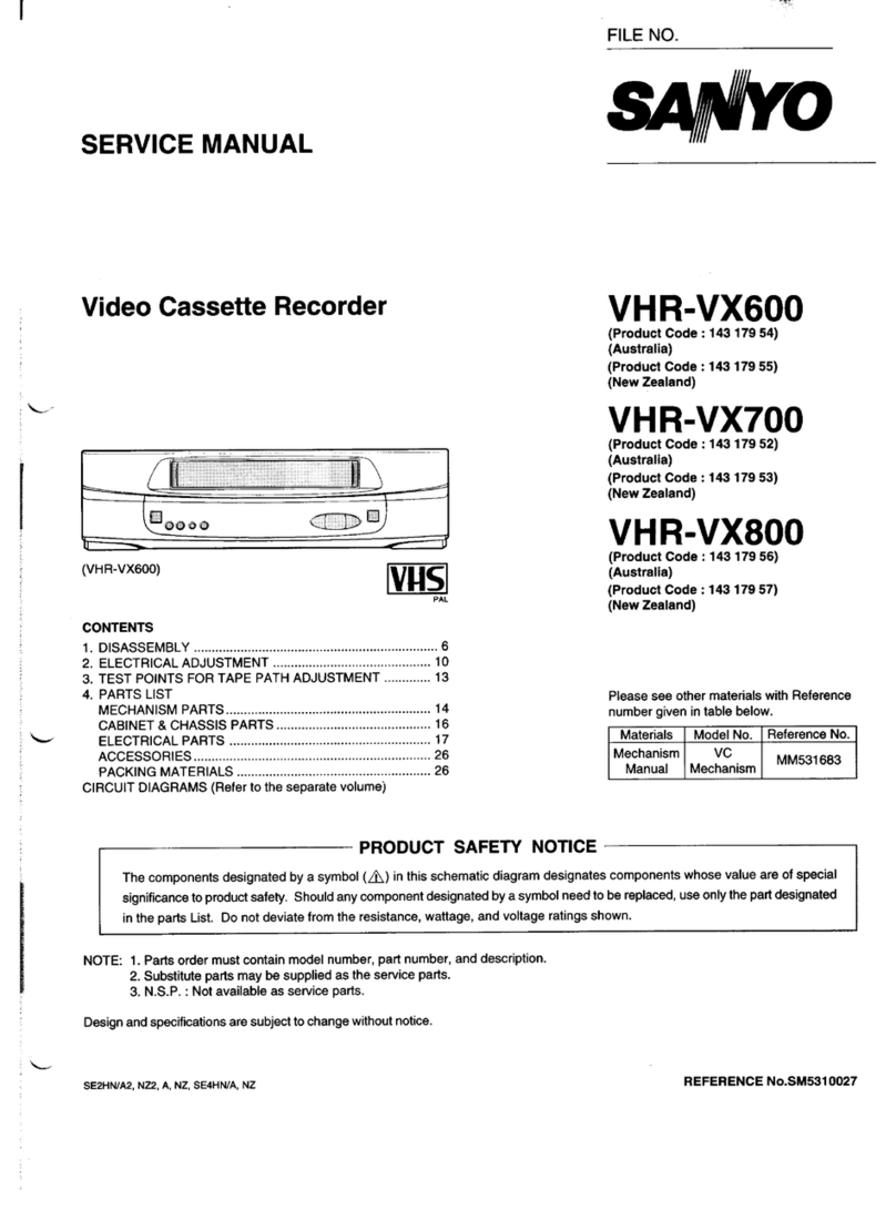
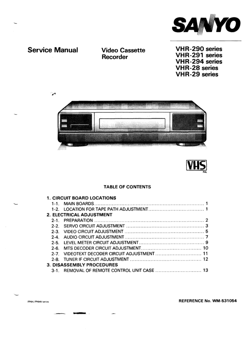
SERVICE MANUAL
Video Cassette Recorder
s*O
VHR-690
(New Zealand)
VHR-690
VHR-699
(Austraha)
VHR-796E
(U. K.)
~f[lo‘“-0
lj Ioa
m~~m ml ;‘@
CONTENTS )1I
SELF-DIAGNOSIS DISPLAY .................................................... 2
1. DISASSEMBLY .................................................................... 5
2. ELECTRICAL ADJUSTMENT .............................................. 9Please see other materials with Reference
3. TEST POINTS FOR TAPE PATH ADJUSTMENT .............15 number given in table below.
4. PARTS LIST
—MECHANISM PARTS ......................................................... 16
CABINET &CHASSIS PARTS ........................................... 19
ELECTRICAL PARTS ........................................................ 20
ACCESSORIES .................................................................. 30
PACKING MATERIALS ...................................................... 30
CIRCUIT DIAGRAMS (Refer to the separate volume)
Materials IModel No. /Reference No. ]
rpROD”cTsAFE
The components designated by asymbol (~) in this schematic diagram designates components whose value are of special
significance to product safety. Should any component designated by asymbol need to be replaced, use only the part designated
in the parts List. Do not deviate from the resistance, wattage, and voltage ratings shown.
NOTE: 1. Parts order must contain model number, part number, and description.
2, Substitute parts maybe supplied as the service parts.
3. N.S.P. :Not available as service parts.
Design and specifications are subject to change without notice.
PK4HN/NZ, A2, A, E6 14316317,16, 15,26 REFERENCE No.SM531 545

SELF-DIAGNOSIS DISPLAY
Mechanism Mode Display/ Head Output Drop Warning Display/ Cylinder Rotation Accumulated
Time Display
This unit displays the diagnosis contents of abnormalities and the mechanism, mode on its disptay panel in 2-digit numbers.
When the head playback output has dropped. the “L” sign will be blinked. Some models (listed later) will also display the cylinder
rotation accumulated time.
These display shows the outline of the problems. Use it as areference when servicing the unit.
1.
.
●
.
●
Self-Diagnosis Contentes and Mechanism Mode Display
When the STOP button on the remote control is pressed for about 10 seconds continuously, the self-diagnosis number will be
displayed on the reception channel display of the display panel and number indicating the failed mechanism mode (changed mode
when beingShified)on the tapecounter “seconds” display fOr 10 seconds each.
During self-diagnosis display, displays other than the diagnosis number/mecharlis.m mode humber and the cylinder accumulated
rotation time display described later (some models only) will be turned off and when displays end, the normal display will be
returned automatically.
Refer to “Self-Diagnosis Contents” for the self-diagnosis numbers and the “Mechanism Mode Display Contents” for the
mechanism mode numbers.
When the “O” button on the remote control unit is pressed during display, and clearing the self-diagnosis display and mechanism ._
mode display
r
Display panel 171: ;’””? i“””””:!‘~“:’’””i~“’’” 177
IJ _l ~....l ;,,,.j “’”1.......$ ... l_l II
‘1 Ii
Self-Diagnosis number Mechanism mode number
(Reception channel display) (Tape counter “Seconds” display)
Self-Diagnosis Contents
No.
00
01
02
03
04
05
Problem Main Possible Cause Mechanism Operations and
State After Occurrence
There is no abnormality in the mechanism.
The cylinder motor does not rotate.
The take-up reel does not rotate.
The capstan motor does not rotate.
The tape cannot be loaded with the
cassette inserted.
(But unloading can be performed.)
Tape loading and unloading cannot
be performed with the cassette in-
serted.
●The cylinder motor is faulty.
●The control of the cylinder motor is
faulty.
●The tape winds around the cylinder.
●The take-up reel is caught
●The reel belt is faultv.
●The take-up torque has decreased.
●The capstan motor is faulty.
●The control of the capstan motor is
faulty.
●Error in the operations of the tape
loading mechanism.
●Foreign particles in the tape load-
ing mechanism.
“The tape end sensor is faulty.
●The reel brake of the tape cassette
has not been released.
●The tape guide is caught.
●The loading motor is faulty.
●The control of the loading motor is
faulty.
Shifts to the STOP mode.
Shifts to the STOP mode,
Shifts to the STOP mode
Unloads, shifts to the INITIAL mode,
and the power goes off.
The power is forcibly turned off with
the mechanism at its current position.
./
.
u
–2–

1
No. Problem Main Possible Cause Mechanism Operations and
State After Occurrence
Front unloading cannot be performed ●The cassette drive mechanism is Front loads and shifts to the STOP or
when ejecting the cassette, faulty. INITIAL mode.
(Front loading can be performed.) ●The front door is caught, ●When the power switch is turned on
before eject operations: Shifts to the
06 STOP mode.
●When the power switch is turned off
before eject operations: Shifts to the
INITIAL mode and the power goes
off.
Front loading and front unloading can- ●The tape cassette is caught in the The power is forcibly turned off with
not be performed when ejecting the cassette drive mechanism. the mechanism at its current position.
cassette. “The main cam and front rack gear of
07 the front loading mechanism have
not engaged properly.
●The gears of the front loading drive
mechanism have not engaged prop-
erly.
The mechanism becomes 1(RE- “The mechanism mode switch con- The power is forcibly turned off with
08 VIEW) while moving from 2(IDLER), tact is faulty. the mechanism at its current position.
3(STILL), 4(BRAKE), and to 5
(STOP)
The mechanism becomes 7(INITIAL) sThe mechanism mode switch con- Carries out tape take-up operations,
09 while moving from 1(REVIEW), 2tact is faulty. shifts to the INITIAL mode, and the
(IDLER), 3(STILL), 4(BRAKE), and power goes off.
to 5(STOP).
Note: For details of mechanism operations corresponding to the mechanism positions of the self-diagnosis numbers 08 and 09 above,
refer to the separate volume on the V95 1mechanism manual, These manual reference numbers are shown in the cover.
Mechanism Mode Display Contents
00
01
02
03
04
05
06
07
Mechanism Mode Mode No.
CASSETTE OUT
STANDBY
STOP
STILL
REC-PAUSE
AUDIO DUBBING-PAUSE
FRAME ADVANCE
SLOW
08
09
10
11
12
13
14
15
1
Mechanism Mode IMode Nc
PLAY
REC
AUDIO DUBBING
X2 SPEED PIAY
CUE
REVIEW
FAST FORWARD
REWIND
16
17
18
19
99
Mechanism Mode
VIDEO INSERT
VIDEO INSERT-PAUSE
AUDIO/VIDEO INSERT
REVERSE X2 SPEED PLAY
OTHERS
I
2. Head Output Drop Warning Display
.When the STOP button on the remote control is pressed for 10 seconds continuously 10 seconds after play starts, “L” will be
displayed blinking at the first digit of the minutes position on the tape counter when the head output is lower than the specified
value to indicate an abnormality.
●The cause of the abnormality maybe due to drop in the playback output caused by drop in the efficiency of the cassette used or
head clogging. Refer to “Head Playback Output Voltage Check” as ameans to judge the abnormality.
Display panel 171- :“””””” :“”’”’”$ I?‘~ 177 ‘
IJ 2‘1
,,,‘, _““LIE
I4I
<6,
Head output drop warning display
(Tape counter”1 st digit of Minutes.” position)
–3–

Head playback output VOHa9e check
. .
Warning
:assette Used Envelope Detection Output Voltage
Display Main Cause
Envelope detec- 4V -----------------------------------
k+”’-og’v !%:::::::::::
When the output voltage differ-
Cassette tlon output
(IC301 Pin 25 or
with normal R3032Markside:
playback –see Fig. 2-l-1) OV
output Switching pulse normal
(TPI 83: see Fig. CH-1 CH-2
2-1-2)
Envelope detec- ~v ................................... When the output voltage differ-
tion output
(IC301 Pin 25 or
“L” blinking R3032Markside:
see Fig. 2-l-1) ov k~~::~han :a:g;;;;:
Switching pulse
(TP183: see Fig. CH-1 CH-2 ●One video head is clogged
Recorded 2-1-2) ●One video head has worn out
cassette
(with tabs) When the average output volt-
Envelope detec- 4V ...................................
tion output
(IC301 Pin 25 or
R3032 Mark side:
11~1blinking see Fig 2-l-1) OV ~,,,ha. ~?!!!;;:;:;;~
Switching pulse
(TPI 83: see Fig.
●Both video heads are clogged
CH-1 CH-2
2-1-2) ●Both video heads have worn
out
Envelope detec- ~v ...................................
tlonoutput
(IC301 Pln 25 or
“L” blinking R3032Markside:
Rental see Fig.2-l-1) ov k!m:~han f==::
Switching pulse
cassette (TP183: see Fig. CH-1 CH-2
(without tabs)
●One video head is clogged
2-1-2) ●One video head has worn out
●Some rental cassettes may have extremely low video playback outputs even when both video heads are normal.
As the average output voltage of the two heads may be less than 0.5V for some, no warning displays will be
shown,
3. Cylinder rotation accumulated time display
.Press the STOP button on the remote control for approximately 10 seconds and the cylinder rotation accumulated time excluding
the cassette out and standby operation time will be displayed on the “Hours” display in units of 100 hours. (“33” will be displayed
for 10 seconds for 3,200 to 3,299 hours.)
.To erase the cylinder rotation accumulated time display, press the RESET button on the remote control during the accumulated
time display.
[L______ ~
I
Cylinder rotation accumulated display (Tape counter “Hours” display)
-
–4–

L
1. DISASSEMBLY
1-1. REMOVAL OF CABINET, MECHANISM UNIT, AND MAIN BOARD
REMOVING THE CABINET PARTS (Fig. l-l-l) 1. First, remove the red screw Cj)of the TM-2 PWB, spread out
1. Remove the cabinet and bottom cover by removing the four the lock clamps (B) and (C) in the arrow direction slightly
screws CDand four screws z. and remove the TM-2 PWB and TM-1 PWB as shown in
2. Remove the front panel by removing the locks of the clamps Fig, 1-1-2,
(A) using ascrewdriver, etc. and slightly rotating the bottom 2. Remove the screw @at the back of the chassis.
part in the direction of the arrow. 3. Remove the red screw @in the chassis, remove the red
screw .$, and remove the holder in this order,
Notes: ●Electrical adjustments for the this model can be 4. Remove the two screws @and two screws Oof the
performed with only the cabinet removed. mechanism unit. The two screws @of the cassette tray can
●When replacing the bottom cover, do not tighten the be removed easily by pushing the tray lock lever in the
screws @too much. Excess tightness may damage arrow direction to remove the lock as shown in the enlarge
the screws taps on the chassis. view Aand by pushing the lid opener lever in the arrow
direction to remove the lock as shown in the enlarge view
REMOVING THE MECHANISM MAIN UNIT AND THE B.
CP-1 PWB ASSEMBLY (Fia. 1-1-2 and 1-1-3) 5. Lift up the whole mechanism unit and main board (CP-1
.- PWB assembly), and as shown in Fig. 1-1-3, push the two
After removing the cabinet parts, remove the mechanism unit lock clamps (D) of the chassis in the arrow direction so that
and the CP-1 PWB assembly connected as follows. they can be removed from the chassis.
M-PK4HN/E-l
Front Panel \Main “nit
,,,.
.W
Q)&
Fig. 1-1-1
–5–

M-PK4HN/E-2
Tray Lock Lever
B
Fig. 1-1-2
M-PK4HN/E3
TM-2
PbV13Assembly
Chassis
Fig. 1-1-3 -
–6-

1-2. TEMPORARILY SETTING UP AND CONNECTING CP-1 PWB ASSEMBLY
The following is an example of how to place and connect the main board without ajig, when repairing the CP-1 PWB assembly.
1. Place the mechanism unit and main board up side down as 2. Operete the unit using the buttons on TM-1 PWB or the
awhole on a flat surface with foil side of the main board remote control.
facing up.
‘i’+
L
‘L
M-PK4HN/E-4 CP-1 PWB Assembly (Foil side)
\
Mechanism Main Unit. \ (3
TM-I’PWB’ ?+-./ /\
Cassette Cotipartment yu /-- rM-2 PWB
~
jr
Fig. 1-1-4
1-3. INSTALLATION OF THE FRONT PANEL
When installing the front panel to the chassis after repaires and adjustments.
1. Pressing down the door opener lever of the mechanism Note: Opened cassette door position does not install the front
main unit. panel to the chassis.
2. Set the cassette door to half-opened state as shown in Fig.
1-1-5, and install the front panel to the chassis.
M-PK4HNE-5
(PositionA) Cass&te Door
(PositionB)
Fig. 1-1-5
–7–

1-4. CIRCUIT BOARD LOCATIONS
L-PK4HN/E
‘;;;’;E’YA rv’-’psembsymb’y
(VH?3D6~;~~i=)\ /~ A\,\ /-,’-l ,”’ (VHR-7,,E)
TN-3/TN-5 P“’ —\ /\” x/1 /
\/ \ // 1A L
W(y
c%
TM-2 P“’
<,pw’~-
--
-
–8–

2. ELECTRICAL ADJUSTMENT
VCR PRESEITING
This VCR need three basic presetting by using the menus displayed on-screen. After all connection have been made, then follow steps
1to 3to preset the VCR.
The three presetting steps will be displayed in sequence on TV screen. The setting are entered with the remote control.
Turn on the VCR
1. Adjusting the TV receiver to the video channel: The AUTO SETUP screen will appear. When the video channel has been preset,
press the OK button on the remote control.
2. Country selection: Using the numeric button, select the country of use,
3. Language selection: When the desired language has been select, press the MENUITV button directly before prevent auto tuning
will start,
When steps 1to 3have been finish, ready to operate the all operating mode,
2-1. SERVO CIRCUIT ADJUSTMENT
.These adjustments should be done upon completion of the tape transport adjustments.
.If the tape transport adjustments (except the tilt adjustment) are done after these adjustments, follow the procedures again in
section 2-1-3, “switching position adj.”
●When acassette tape is loaded, auto-tracking will be set immediately after starting the first playback. As this will daviate the
tracking center set, be sure to press the channel buttons (+) or (–) once directly after starting playback to prevent auto-tracking
from being set,
2-1-1. TEST EQUIPMENT AND STANDARDS REQUIRED
Oscilloscope Vertical sensitivity :5 mV/DIV, external trigger
Bandwidth :more than 10 MHz
]Alignment Tape IVHJ-0009 or VHJ-0023 :SP mode, monoscope, 6KHz I
Blank Tape VHS-type cassette tape
Monitor TV
2-1-2. LOCATION OF ADJUSTMENT POINTS
P54400D
CP-1 PWB (Foil side) Fig. 2-1-1
–9–

P55900B
“’82?1I-’TP’8’’”P’V’”V’”
TP183 m
Shield case m- \\ I
VP-1 PWB Assembly Fig. 2-1-2
Note:
.Self-recording means “Record any broadcasting or video
signal and play back the just-recorded portion. ”
2-1-3. SWITCHING POSITION ADJ.
Measuring Point Measuring Equipment
TPIO1 Oscilloscope
(VIDEO OUT)
TP183 (SW-P)
17
Adj. Condition
PLAY mode
Alignment tape
(VHJ-0009 or
VHJ-0023)
Adj. Location Adj. Value
VR351 (SW-P) 6.5 H+0.5 H
1. Play back the alignment tape.
2. Set the tracking control position to the center by pressing
CHANNEL buttons (+) and (–) simultaneously.
3. Adjust VR351 (SW-P) so that the width of “T’ becomes 6.5
H*0.5 Has shown in Fig. 2-1-3.
I
WS-SWP
rT=6.5H 20.5H
lH 0.5H 1
Front edge of”
vertical sync signal
?t
J‘Rise RF. SW. PULSE
Fig. 2-1-3
2-1-4. SLOW TRACKING ADJ.
F
Measuring Point
Picture of
monitor TV
L
pleasuring Equipment
Color bar generator
or
broadcasting monitor I
Adj. Condition
Self-recording
(SP mode)
SLOW mode
Blank tape
Self-recording
(LP mode)
SLOW mode
Blank tape
IAdj. Location IAdj. Value I
1
CHANNEL (+) button
ICHANNEL (-) button I . -‘I
1.
2.
3,
4.
5.
6.
Set the tracking control to the center position by pressing
CHANNEL buttons (+) and (–) simultaneously.
Play back the self-recorded portion and set the VCR in the _
SLOW mode with the remote control unit.
Confirm that there is no noise on the slow playback display.
Press the CHANNEL button (+) about three times and
check that noise dose not appear at the upper part of the
display,
Adjust the tracking control to the center again.
Press the CHANNEL button (–) the same number of times
as in the step 4(about three times) and check that noise
dose not appear at the lower part of the display.
Note:
.CHANNEL button also servers as aTRACKING button.
I
–lo–
—

L
L
2-2. VIDEO CIRCUIT ADJUSTMENT
.In this model, video circuit adjustments are not performed. To check whether operations are normal, check the AGC level and
PB-Y level using the following method.
.Use the adjustment relay jig to provide simple repairing of the VP-1 PWB assembly.
2-2-1. TEST EQUIPMENT AND STANDARDS REQUIRED
Color Bar Signal Generator PAL Color bar signel with 100% white level (EBU color bar signel)
Oscilloscope Vertical sensitivity :5 mV/DIV, external trigger
Bandwidth :more than 10 MHz c,
Oscilloscope Probe Input capacity :less than 25 pF (10:1)
less than 40 pF (1:1) I
Covering frequency :DC-4OMHZ(1O:1)
DC-30 MHZ (1:1)
Digital Voltmeter DC range
Alignment Tape VHJ-0008 or VHJ-0023 :SP mode, color bar, 1kHz
I(Color bar signal waveform is described below. Refer to Fig. 2-2-1)
IAdjust Relay Jig IVHJ-0067 :12-wire flat cable for VP-1 PWB assembly
ALIGNMENT TAPE COLOR BAR SIGNAL
WPV-TCS m
Io.7vp-p
lvp-p IImn——
----
11— 100% White
II-f
‘H.Sync Si&al
Color bar signal waveform (VHJ-0008)
Fig. 2-2-1
Color bar pattern (VHJ-0008) on monitor TV
Fig. 2-2-2
ADJUSTMENT RELAY JIG
Connect the flat cable end from the cylinder assembly to the VP-
1PWB assembly using the relay jig to provide simple repairing
or adjustment of the VP-1 PWB assembly, as shown in Fig. 2-
2-3, Further, when adjusting the VP-1 PWB assembly, be sure
to make contact an end of shield case with bracket of the VP-
1PWB assembly to maintain the shield effect. If the VP-1 PWB
assembly does not contact, there is insufficient ground and no
proper play back image can be obtained
RJ-PA4HIU .,,
VP-1 PWB Assem
Relay Jig
VHJ-0067
FlatCable
CylinderAssembl
Fig. 2-2-3
I
-F
/.=$/1
—
1
L.1 i
e-s-s Qi3
—.—- .- —
-11–

2-2-2. LOCATION OF TEST POINTS
P54400D
.............-. 51
(~”; VR351
*0
‘--’m
CP-1 PWB (Foil side) Fig. 2-2-4
2-2-3. AGC LEVEL CHECK. 2-2-4. PB-Y LEVEL CHECK.
Measuring Point Measuring Equipment Adj. Condition
IC 101 pin 46 Color bar generator E-E mode
Oscilloscope
(10:1 probe)
Adj. Location Specified Value
—0.5 Vp-p f0.05 Vp-p
Measuring Point Measuring Equipment Adj. Condition
TP101 Oscilloscope PLAY mode
(VIDEO OUT) Alignment tape
(VHJ-0008 or
VHJ-0023)
Adj. Location -
Specified Value
—1Vp-p *0.15 Vp-p
1. Connect the color bar generator to the video input terminal
2. Make sure that the AGC level is 0.5 VP-P t0.05 VP-P as 1. Terminate the video output terminal with a75~) resistor.
shown in Fig. 2-2-5.
WV-AGC 1007. White
/
0.5 vp-p?o.05 Vp-p
h-r
t
%
Fig. 2-2-5
–12-
2. Make sure that the video luminance signal level is 1Vp-p
*0.15 Vp-p. (Refer to Fig. 2-2-6)
WV-PBY 07. White
1vp-
1
L--u u

2-3. AUDIO CIRCUIT ADJUSTMENT
●Before making these adjustments, be sure to make the .Before making these adjustments (except the ACE heads
adjustments described in the tape path adjustment, espe- adjustments), be sure to make the adjustments described
cially the ACE heads adjustments (refer to the separate in section 2-1, “Servo Circuit. ”and section 2-2. “Video
volume “Mechanism Manual”) so that the tape traveling Circuit .“
between the supply side guide roller and loading guide post
runs without fluttering or curling.
2-3-1. TEST EQUIPMENT AND STANDARDS REQUIRED
Oscilloscope Vertical sensitivity :10 mV/DIV
Bandwidth :more than 30 MHz
AC Voltmeter Effective value indication
Input frequency :10 Hz-20kHz
Input impedance :more than 1MQ
Measurement level :1mV (full scale)
Frequency Counter Input frequency :20 HZ- IO MHZ
L- Blank Tape VHS-type cassette tape
2-3-2. LOCATION OF ADJUSTMENT POINTS
L
P54400D rJ:._.....
...........’
TM-71
TM-8
PWB
Power
‘sS;ply
7
----
,,
0VR234
H
,.... ,-...,
CN352 1:
,......
1
0CN351
37
13 Iclol
25
w
R3032 CN303;””>
J3054
2 “’’0:01 “’”’”a
~
51
A
CP-1 PWB (Foil side) Fig. 2-3-1
–13–

AUDIO NORMAL CIRCUIT
Note:
.Set the following remote control button to the positions
indicated below, before making following adjustments.
REMOTE CONTROL BUITON POSITION
TAPE SPEED SP
INPUT AV
AUDIO L
2-3-3. BIAS LEVEL ADJ.
Measuring Point Measuring Equipment Adj. Condition
TP232 (HOT) Oscilloscope REC (SP) mode
TP231 (COLD) AC voltmeter Blank tape
Frequency counter
Adj. Location Adj. Value
VR231 (BIAS) 26 mVrms
1. Load the VCR with ablank tape and select the REC (SP)
mode without all incoming signal.
2. After confirming on the oscilloscope that a 70 kHz +5kHz
sine wave is being output, adjust VR231 (BIAS) so that the
AC voltmeter’s reading is 26 mVrms.
AUDIO FM (Hi-Fi) CIRCUIT
Note:
.Set the following remote control button to the positions
indicated below, before making following adjustments.
REMOTE CONTROL BLJITON POSITION
TAPE SPEED SP
INPUT AV
AUDIO Lor R
2-3-4. A-FM CARRIER FREQUENCY ADJ.
Measuring Point Measuring Equipment Adj. Condition
TP233 Frequency counter REC (SP) mode
Blank tape
Adj. Location Adj. Value
VR233 (L-FO) 1.4MHz f 5 kHz
VR234 (R-FO) 1.8 Mfiz t5kHz
l--
1.
2.
3.
4.
5.
6.
Press the INPUT button on the remote control and select
“AV”.
After recording/playing back for 10 to 20 seconds with the
no-signal input, select Lch with the AUDIO button on the
remote control, and check the reading of the counter
connected to TP233.
If the carrier frequency of Lch is higher than 1.4 MHz, rotate
VR233 (L-FO) slightly to the right, towards the board
component side.
Next switch to Rch and check the reading of the counter. If
the carrier frequency of Rch is higher than 1.8 MHz, rotate
VR234 (R-FO) slightly to the right, towards the board
component side.
After recording/playing back for 10 to 20 seconds with the
no-signal input again. If the carrier frequency of Rch is
higher than 1,8 MHz, rotate VR234 (R-FO) slightly to the _
right.
If lower, rotate slightly to the left, Switch to Lch using the
AUDIO button. If the carrier frequency of Lch is higher than
1.4 MHz, rotate VR233 (L-FO) slightly to the right. If lower,
rotate slightly to the left.
Repeat recordinglplay back and checking of the frequencies
until the carrier frequency of Rch becomes 1.8 MHz f5
kHz and that of Lch becomes 1.4 MHz *5kHz.
Note:The carrier frequency of the part recorded first is not
stable because it is written over. Therefore, no signal
recording for 10 to 20 seconds must be performed.
-
–14–

2-4. IF CIRCUIT ADJUSTMENT
‘L
Note: The 3in tuner dose not need any adjustments, because
precise adjustments were down before shipment.
●In this model, the circuits of the TUNER, IF, and RF I
converter have been made into one. Therefore, should one
circuit malfunction, the whole unit must be replaced.
●The adjustments for the IF (RF AGC) circuit of the 3in 1
tuner are described below.
2-4-1. TEST EQUIPMENT AND STANDARD REQUIRED
Monitor TV
2-4-2. LOCATION OF ADJUSTMENT POINT
AD-1
PWB
3in 1Tuner Fig. 2-4-1
2-4-3. RF AGC ADJ.
Measuring Point Measuring Equipment Adj. Condition
Picture of Monitor TV E-E mode
monitor TV
Adj. Location Adj. Value
VR (RF AGC) SIN is best point
(on the 3in 1tuner) 1
1.
2.
3.
4.
Connect the monitor TV to the VHFIUHF antenna output
terminal.
Connect the VHF or UHF antenna to the VHFIUHF antenna
input terminal,
Receive the middle electrical field (70 dBp -90 dBp) of the
VHF or UHF channel, and slowly turn the VR (RF AGC)
from the point where snow-noise is present to the point
where it just disappears from the monitor TV.
Confirm by monitor TV that there is no beat and saturation
(S/N is best point) when receiving any TV channel.
3. TEST POINTS FOR TAPE PATH ADJUSTMENT
Test points TP182 (ENV) and TP183 (SW-P) for tape path adjustment are shown in figure below.
‘L For adjustment, refer to the separate volume “V951 Mechanism Manual (MM531 433).”
Shield case m= \\ r’ TP181 Inputlevel]
I
(QJ
IVP-1 PWB Assembly Fig. 3-1
I
–15–

4. PARTS LIST
MECHANISM PARTS
Note:
1.This model uses two types of mechanism-the V951 mechanism and V9511mechanism shown in Fig Aand Fig B.
These mechanism can be differentiated by whether the Location Number 12000 mounting cylinder is equipped or not.
The mechanism with the mounting cylinder is the V951 mechanism, and the one without is the V9511mechanism.
2.Parts marked with (#A) under Description in the parts list are for the V951 mechanism, while those marked (#B) are
for the V9511mechanism.
3.Take note that (#A) and (#B) parts have no interchangeability.
4.For Location numbers 801OA and 801OB, parts marked (#c) and (#D) in DESCRIPTION are not interchangeable with each
other.
However, these are Interchangeable when 801OA and 801OB are in the assembled state.
(#C) and (#D) can be differentiated from the color and height of the roller (801OB).
(#C) is gray and toll and (#D) is black and short.
5.For VHR-690, VHR-699
Do not disassemble the Locatjon No.11000 assembly cylinder.
As It is not possible to replace only the upper cylinder or lower cylinder, replace the whole Location No.11000 assembly
cylinder.
~N PASTSNO. DESCRIPTION
MECHANISMPARTS 1
11000
OR
OR
11100
11200
11300
12000
OR
13000
OR
21000
22000
30000
OR
OR
40000
50000
0099
0100
0300
040B
040C
040D
0800
0900
1000
1100
6073
6102
6070
10120
10140
10150
OR
10400
OR
20100
20200
OR
20210
OR
OR
20300
OR
20310
20400
20410
20600
20700
6131724259
6131645981
6131683587
6130962751
6131646001
4110381608
6131550759
6131598980
4110474805
4120488601
6130224019
6450084454
6130814036
6130972170
6131637986
4120365001
4120364905
6131520578
6131520738
6131520660
6131520417
6131520707
6131520424
6131522794
6131522800
6131519480
6131519299
4120488205
6131516618
4110217907
4071621102
4071628705
4070430101
4071658108
4120488106
4120526204
6131605503
6131681514
6131604193
4120158504
4120158900
4120215306
6131716896
6131518889
4120487505
6131519701
4120454606
6131522749
6131522756
ASSY,CYLINDER,4H6P-R3,EXCEPTVHR-796E
(SEE NOTE)
COMPL,CYLINDER,4H6P-R2,VHR-796E ONLY
ASSY,CYLINDER,LWR6K,VHR-796E ONLY
ASSY,CYLINDER.UPR 4H6P-R2.vHR-796E ONLY
SCR PAN+W3x8; VHR-796E ONLY
MOUNTING,CYLINDER(#A)
SCR PAN+FLG2. 6X6 (#A)
SPECIAL SCREW2. 6x7 (#A)
ROTOR,MOTORCYL
MOTOR,STATOR,CYL DC 2W
SPACER,MOTOR,EXCEPTVHR-796E
SPACER,MOTOR,VHR-796E ONLY
SPECIAL SCREW2. 3x6
SPECIAL SCREW2.3X1O
COMPL,CASSETTEMEChlNISM
STAND,L
FRAME,UNDER
SPRING,LID OPENER
LEVER,R31LEASE
SPRING,TRAYLOCK
GEAR,LOCK
GEAR,PINION
LEVER,DOOROPENER
HOLDER,GEAR
SPECIAL SCREW-2,6X6
PAD
SCR S-TPG BIN 4X12
LEDLN59L
PHOTODIODEPN263L-(NC)
PHOTODIODE0N2170-R
PHOTOCOUPLESG-105F
SPECIAL SCREW2. 6x8 (#A)
SPECIAL SCREW-2.6x5.5
ASSY,REEL SUPPLY
ASSY,REEL TAKEUP
ASSY,REEL TAKEUP
SPECIALWASHER3. 1x6x0.5
SPECIALWASHER3. 1x6x0.4
SPECIALWASHER3.1x6X0. 3
COMPL,MOUNTINGCLUTCH
SPECIAL SCREW-2.6x4
PULLEY,REEL
SPECIAL WASHER2.4 X6X0.25
GEAR,MEL S
GEAR,REEL T
~N
30300
30400
30500
30600
30700
30800
30900
31100
31700
31800
40100
40200
40300
50100
OR
50110
50200
50200
50210
5050A
OR
5050B
5050C
5060A
OR
5060B
5060c
50700
50800
50900
51000
51010
51100
51110
6090A
OR
6090B
6090C
60910
61000
61100
701OA
701OB
701OC
70200
70300
70400
10410
801OA
OR
801OB
OR
PAM’Sm. DE&2RIPTION
6131603356 ASSY,BRAKESOFT T
6131520295 SPRING,SOFT TIWU?’ t(V:
6131519411 LEVER,SOFT S
6131520318 SPRING,SOFT S
6131606166 ASSY,BRAKE,S
6131592193 ASSY,BRAKET
6131636996 SPRING,BRAKE Elwl tW
6131520189 SLIDE,ACT BRAKET$i!.!m~,,,-.A
6131518490 ASSY,BRAKECAPSTAN
6131520356 SPRING,BRAKECAPSTAN
6131518759 ASSY,LEVER,BT
6131605282 ASSY,BRAKE,BAND
6131520271 SPRING,BT -,:);.A ii H,
—..—.
6450176432 HEAD,ERASEFULL
6450089749 HEAD,EFL4SEFULL
4120489707 SPECIAL SCREW-2.6X1O
6450176401 ASSY,HEAD,R/P ACE
6450085192 ASSY,HEAD,R/P ACE
4120523500 SPECIAL SCREW2.6x12
6131518858ASSY,MOUNTING,INCLINE s(#A)
6131647237 ASSY,MOUNTING,INCLINE S(#B)
6130220233 ASSY,GUIDE,ROLLER
4120484504 SPECIAL SCREW-2X3
6131518872 ASSY,MOUNTING,INCLINE T(#A)
6131647251 ASSY,MOUNTING,INCLINE T(#B) 23T
6130220233 ASSY,GUIDE,ROLLER
4120484504 SPECIAL SCREW-2X3 !Jr?loq t2
6131644762 ASSY,LEVER,LOAD
6131520387 SPRING,LEVERLGUIDE IK?u[bsT.—
4120488908 SPECIAL NUT-3X3
6131612365 ASSY,LEVER,ACT LGUIDE
4120334106 WASHERSLIT 2,6x5X0.50 /+0,;?.
6131607057 MOUNTING,CATCHER
4120491700 SPECIAL SCREW-2.6X1O
6131519152 GEAR,RACKFRONT
6131604636 GEAR,RACKFRONT
6131519114 GEAR,RACKSTART
6131520226 SPRING,RACKFRONT
4120502802 SPECIAL SCREW-2.6X6
6131519398 LEVER,EP SW
6131523692 SPRING,EP SW
6131518803 ASSY,LEVER,PINCH ROLLER
6131710221 MOUNTING,LIFT PINCH
6131520233 SPRING,PINCH ROLLER
6131563841 CAM,LIFT PINCH
6131520677 GEAR,CAMPINCH
6131520714 MOUNTING,OPENER
4120491106 SPECIAL SCREW-2.6X16
6131597273 LEVER,CLEANER(#C)
6131719606 LEVER,CLEANER(#D)
6131585829 ASSY,ROLLER,CLEANER(#C)
6131719439 ASSY,MOUNTINGCLEANER(#D)
—
..
–16–

i
(Fig A)V95 IMechanism
Note :Parts whose location number are enclosed in ovai marks are for the V95 Imechanism.
They are not interchangeable with the V95 II mechanism parts shown in Fig B.
70 \l
40000
(’%’B )V95 II me~~~f-
N,S.P. :Not availabie as service arts.
MECHANISM-P~RT 1
Note :Parts whose location number are enclosed in oval marks are for the V95 II mechanism.
They are not interchangeable with the V95 Imechanism parts shown in Fig A.
............................. m
/\k /’
/
40000 \/
J
>
801OA
0110 nninn \ /50210 00
701OA
..f ‘Ufu ~~ 5ofIJB ~ ‘ ,1100 \ ~%~’c
‘w
I/’ /i
B
~
207~0 ‘“”
+) A
w
20400 30400 &39,A
_~ +jj@l)
20410
Q!zI!r’-N.S.P. :Not avaiiable as service parts.
MECHANiSM-PART 1
–17–

muxa Pms NJ. DsscRIP?Io~ LOCATION PAFTs NO. DE&cRIP!IoN._ ._
31600
MECNANISM PARTS 26131520349 SPRING,CHANGECLUTCH
40400 6131537583 ASSY,LEVERSPRING BT
10110 6131601574
10130 6450071560
10160 4120487505
10200 4120488304
10700 6131675926
OR 6131530836
10720 4120488007
OR 4120489608
10800 6131658523
OR 6131604179
10810 4120488007
20500 6131604186
20510 4111091605
20800 6131519039
31000 6131520165
31200 6131590991
31300 6131590847
31400 6131520332
31500 6131519459
COMPLPWB,MC-1
SWITCH,MODE
SPECIAL SCREW-2.6X4
SPECIAL SCREW-2,6X8
MOUNTINGCAPSTAN(#F )
MOUNTING,HARNESS(#E)
SPECIAL SCREW-2,6X6 (#F)
SPECIAL SCREW-2.6x3 (#E)
ASSY,EARTHCYL
ASSY,EARTHCYL
SPECIAL SCREW-2.6X6
ASSY,GEAR,FRICTION
WASHERY2.6X6X0.25
BELT,REEL
SLIDE,ACT BRAKES
LEVER,CONTROLBRAKE
COMPL,LEVER,ACTBRAKE
SPRING,RETURNBRAKE
LEVER,CHANGECLUTCH
5030A
5030B
5030C
OR
5040A
5040B
5040C
OR
60100
60200
60300
60400
60500
60600
60610
60700
60800
60810
70500
6131522763 GEAR;LOADS
6131520370 SPRING,LOADS
6131518766 ASSY,LEVER,LOADS(#A)
6131603691 ASSY,LEVER,LOADS(#B)
6131522770 GEAR,LOADT
6131520363 SPRING,LOADT
6131518773 ASSY,LEVER,LOADT(#A)
6131603707 ASSY,LEVER,LOADT(#B)
6450034305 ASSY,MOTORLOADING
6131518599 COMPL,GEAR,WORM
6131519107 DAMPER
6131519138 GEARWHEEL1
6131603790 GEARWHEEL2
6131564008 CAM,MAIN
4120546806 SPECIALWASHER3.6x0.5
6131599017 SLIDE,CRESCENT
6131598997 MOUNTING,CRESCENT
4120488007 SPECIAL SCREW-2.6X6
6450081880 MOTOR,CAPSTANDC 3W
70510 4120487604 SPECIAL SCREW-2.6X6
(Fig C)
Note :Parts whose location number are enclosed in oval marks are not interchangeable between the V95 Imechanism
and V95 II mechanism.
Location numbers 10700 and 10720 have two types of parts.
(#E) and (#F) parts have different shapes, measurements, number of screws, and positions for attaching
the screws.
#E T
20800+ ,\ “\ /“ -
\
;\
.. .... ... . ........ . ... .
10720= i
a
.—
MECHANISM-PART 2
-18–

L!wTK!M Pm%m. DWRIPTIOU
CABINET &CHASSIS PARTS !‘
CH-1 4111370007 SCR L-TPG BIN 3X10 r
CH-2 4110217907 SCR S-TPG BIN 4X12 4
CH-3 6131675698 COMPLPWB,VP-1 4
CH-4 4120525108 SPECIAL SCREW-2.6x12
CH-5 4120289406 SPECIAL SCREW
CH-6 6131634794 COVERTOP
CH-7 4110213800 SCR S-TPG BIN 3X1O
CH-8 6131640771 TERMINAL,EXCEPTVHR-796E
OR 6131636415 TERMINAL,vHR-796E ONLY
CH-10 6131711167 COMPLPWB,CP-l-A, VHR-690(AUSTRALIA)ONLY
OR 6131710481 COMPLPWB,CP-l-A, VHR-690(NEWZEALAND)ONLY
OR 6131710474 COMPLPWB,CP-l-A, VHR-699 ONLY
OR 6131717060 COMPLPWB,CP-l-A, VHR-796E ONLY
CH-11 6450046025 TUNER,RF/TU/IF, EXCEPTVHR-796E
OR 6450076626 TuNER,RF/Tu/IF, vHR-796E ONLY
CH-14 6131669048 COMPLPWB,TN-3,VHR-699,VHR-690(AUSTRALIA)
OR 6131693777 COMPLPWB,TN-5,VHR-690(NEWZEALAND)ONLY
OR 6131616226 COMPLPWB,TN-5,VHR-796E ONLY
CH-15 6131616189 COMPLPWB,AD-5,VHR-796E ONLY
Undesignated numeral shows
Location No.: CH-
N.S. P.: Not available as service parts
K&A?wsi
OR
CH-16
CH-17
OR
CH-19
OR
CH-20
OR
OR
OR
CH-21
OR
OR
OR
CH-22
CH-23
OR
OR
OR
cH-24
CH-25
CH-29
PAlwsm. DKXRIFW No
6131603578 COMPLPWB,AD-5, VHR-699 ONLY
6131665750 COMPLPWB,TB-l, VHR-796E ONLY
6131605091 COVERBOTTOM,VHR-796E ONLY
6131724723 COMPL,COVERBOTTOM,EXCEPTVHR-796E
6131709713 COMPL,PWBTM-2,vHR-796E 0NL%
6131681941 COMPLPWB,TM-2,EXCEPTVHR-796E
6131671294 COMPLPWB,TM-l, VHR-690(AUSTRALIA)ONLY
6131715837 COMPLPWB,TM-1,VHR-796E ONLY
6131711433 COMPLPWB,TM-l, VHR-690(NEWZEALAND)QtiLY
6131664494 COMPLPWB,TM-1,VHR-699 ONLY
6131712331 DOORCASSETTE,VBR-690(NEWZEALAND)ONLY
6131730649 DOORCASSETTE,VHR-796E ONLY
6131721661 DOORcassette, VHR-690(AUSTRALIA)ONLY
6131712324 DOORcassette, VHR-699 ONLY
6131530478 SPRING
6131718197 ASSY,CABINETFRONT,VHR-796E ONLY
6131721654 ASSY,CABINETFRONT,VHR-690(AUSTRALIA)ONLY
6131712171 ASSY,CABINETFRONT,VHR-699 ONLY
6131726963 ASSY,CABINETFRONT,VHR-690(NEWZEAIJ.ND)ONLY
6131540781 DECINDICATOR
6131211001 STAND,FELT, STAND(FRONT)
4110011901 SCR S-’I’PGBIN 3x6
1.&w’
CABINET &CHASSIS PARTS
–19–

ELECTRICAL PARTS
NOTE;
1. Materials of Capacitors and Resistors are abbreviated as follows ;
Resistors Capacitors
MT-FILM Metallized Film Resistor MT-POLYEST Metallized Polyester Capacitor
MT-GLAZE Metallized Glaze Resistor MT-COMPO Metallized composite Capacitor
OXIDE-MT Oxide Metallized Film Resistor TA-SOLD Tantalum Solid Capacitor
AL-SOLID Aluminum Solid Capacitor
NP-ELECT Non-Polarized Electrolytic Capacitor
OS-SOLID Aluminum Solid Capacitors with Organic
Sem iconductive
Electrolytic CaDacitor
2.
3.
4.
5.
6,
.DL-ELECT Double Layered Electrolytic Capacitor
Tolerance of Capacitor (1OPFover) and Resistor are noted with follow symboles.
F............1% G............2% J,.O.........5% K,..,, .......10%
M..........20% N..........30% Z..........60% --20%
CapacitorsU:UF P:PF
Inductors UH :UH MH :mH
N.S.P. :Not available as service parts.
The ceramic capacitors and resistors mounted on the PWB, may be two different types parts, chip (Ieadless) type
or discrete (with lead wire) type.
Therefore, even though the location number is the same, you may encounter either chip or discrete parts on the PWB.
~ii ~— DEwRIPT1ON laA!uoM~DBEcmms
OR
OR
OR
Qlool
OR
OR
OR
Q1OO2
OR
OR
OR
Q1OO3
OR
OR
OR
Q1OO4
OR
Q1OO5
OR
OR
OR
Q1OO6
OR
Q1201
OR
Q1211
OR
OR
OR
Q1221
OR
OR
OR
Q1222
OR
OR
OR
Q1401
OR
OR
OR
Q1402
OR
OR
6131711167 COMPLPWB,CP-1-A,
VHR-690(AUSTRALIA) ONLY
6131710481 CCMPLPWB,CP-1-A,
VHR-690(NEWZEAUND)ONLY
6131710474 CCMPLPWS,CP-1-A,VHR-699 ONLJ
6131717060 CCMPLPWB,CP-1-A,VHR-796E ONLY
(SEMICONDUCTORS)
4050158407 TR 2sc2812-L5
4050158704 TR 2SC2812-L6
4050144509 TR 2sc2412K-R
4050144608 TR 2sc2412K-s
4050158407 TR 2SC2812-L5
4050158704 TR 2sc2812-L6
4050144509 TR 2sc2412K-R
4050144608 TR 2sc2412K-s
4050158407 TR 2sc2812-L5
4050158704 TR 2sc2812-L6
4050144509 TR 2SC2412K-R
4050144608 TR 2SC2412K-S
4050181900 TR 2SC3395
4050293504 TR DTC144EK
4050158407 TR 2sc2812-L5
4050158704 TR 2sc2812-L6
4050144509 TR 2sc2412F-R
4050144608 TR 2SC2412K-S
4050037108 TR 2sA1341
4050002007 TR DTA144EK
4050998300 TR 2sA1782T-Ac
4050061806 TR 2sA933s-R
4050158407 TR 2sc2812-L5
4050158704 TR 2sc2812-L6
4050144509 TR 2sc2412K-R
4050144608 TR 2SC2412K-S
4050158407 TR 2SC2812-L5, VHR-796E ONLY
4050158704 TR 2SC2812-L6, VHR-796E ONLY
4050144509 TR 2sc2412K-R, vHR-796E ONLY
4050144608 TR 2SC2412K-S, VHR-796E ONLY
4050640100 TR 2sA1561-Q, vHR-796E ONLY
4050640209 TR 2SA1561-R, VHR-796E ONLY
4051236708 TR 2SB1320A-Q,VHR-796E ONLY
4051236807 TR 2SB1320A-R,VHR-796E ONLY
4050026508 TR 2SA1179-M5
4050026706 TR 2sA1179-M6
4050020308 TR 2SA1037K-R
4050020407 TR 2sA1037K-s
4050026508 TR 25A1179-M5,vHR-796E ONLY
4050026706 TR 2sA1179-M6,vHR-796E ONLY
4050020308 TR 2SA1037K-R,VHR-796E ONLY
Q1402
Q2301
OR
Q2302
Q2302
Q2303
OR
Q2304
OR
Q2305
OR
Q2306
OR
OR
OR
Q2307
OR
OR
OR
Q2308
OR
Q2309
OR
Q231O
OR
Q2311
OR
Q2312
OR
Q2313
OR
Q2320
OR
Q2321
OR
Q2322
OR
Q2323
OR
Q2324
OR
Q3001
OR
Q3002
OR
Q3003
OR
Q3301
Q3302
OR
Q3401
4050020407 TR 2SA1037K-S,VHR-796E ONLY
4050037108 TR 2sA1341, vHR-699, vHR-796E
4050002007 TR DTA144EK,vHR-699, VHR-796E
4050181900 TR 2SC3395, VHR-699,VHR-796E
4050293504 TR DTC144EK,VHR-699,VHR-796E tsn@izsbnU
4050181900 TR 2SC3395 ~rloit6mJ
4050293504 TR DTC144EK s!Ou;.q.z.’kl
4050452208 TR 2sc3900
4050005305 TR DTC143TK
4050452208 TR 2sc3900
4050005305 TR DTC143TK
4050158407 TR 2SC2812-L5
4050158704 TR 2sc2812-L6 +-s
4050144509 TR 2sc2412K-R
4050144608 TR 2SC2412K-S
4050158407 TR 2sC2812-L5
4050158704 TR 2sc2812-L6
4050144509 TR 2sc2412K-R P
4050144608 TR 2sc2412K-s f
4050160101 TR 2sc3331-T irwb&4
4050160200 TR 2sc3331-u
4050180101 TR 2sc3331-T
4050180200 TR 2sc3331-u
4050181900 TR 2sc3395 j--. rr
4050293504 TR 0TC144EK
4050037702 TR 2SA1346
4050001208 TR DTA124ES b-&t
4050181900 TR 2sc3395 Jr
4050293504 TR DTC144EF
4050037702 TR 2sA1346 <
/’
%
4050001208 TR DTA124ES L.,
4050452208 TR 2SC3900, VHR-796E ONLY
4050005305 TR DTC143TK,VHR-796E ONLY /
4050452208 TR 2SC3900, VHR-796E ONLY ot ‘
4050005305 TR DTC143TK,VHR-796E ONLY or
4050037108 TR 2SA1341,VHR-796E ONLY
4050002007 TR 0TA144EK,VHR-796E ONLY
4050181900 TR 2SC3395,VHR-796E ONLY
4050293504 TR DTC144EK,VHR-796E ONLY
4050037108 TR 2sA1341, vHR-796E ONLY
4050002007 TR DTA144EK,VHR-796E ONLY
4050181900 TR 2SC3395, VHR-796E ONLY
4050293504 TR DTc144EK,VHR-796E ONLY
4050144509 TR 2sc2412K-R, vHR-796E ONLY
4050144608 TR 2SC2412K-S,VHR-796E ONLY
4050037405 TR 2sA1344
4050000409 TR DTA114EK
4050005305 TR DTC143TK,VHR-690(NEWZEALAND), VHR-796E
4050037108 TR 2SA1341,VHR-690(NEWZEALAND),VHR-796E
4050002007 TR DTA144EK,VHR-690(NEWZEALAND), VHR-796E
4050848209 TR 2SC2960-F-SPA w
-20–
Other manuals for VHR-690
1
This manual suits for next models
2
Table of contents
Other Sanyo VCR System manuals

Sanyo
Sanyo TLS-224P User manual

Sanyo
Sanyo SRT-4040 User manual

Sanyo
Sanyo VHR-M341 User manual

Sanyo
Sanyo SRT-8040 User manual

Sanyo
Sanyo VHR-VK910A User manual

Sanyo
Sanyo SRT-612DC User manual

Sanyo
Sanyo VHR-H803E User manual

Sanyo
Sanyo VHR-330EV User manual

Sanyo
Sanyo VHR-220 series User manual

Sanyo
Sanyo VHR-H531 User manual