FILE
NO.
BASIC
SERVICE
TECHNICAL
SANYC
INFORMATION
4]
FISHER
Video
Cassette
Recorder
V95
[MECHANISM
VHS!
PAL
SECAM
NTSC
Contents
1.
MAINTAINING
AND
CHECKING
3-7.
CAPSTAN
MOTOR
...........00cceeeeee
15
4.
MECHANISM
CHECKS
AND
THE
MECHANISM
3-8.
LOADING
MOTOR
ASSEMBLY
ADJUSTMENTS
1-1.
REGULAR
CHECKS
AND AND
WORM
GEAR
ASSEMBLY
...
16
4-1.
REEL
TABLE
TORQUE
CHECK.......27
MAINTENANCE
ITEMS
..........0.0000e-
2
3-9.
PINCH
ROLLER
PRESSURE
4-2.
ADJUSTING
THE
BT
LEVER
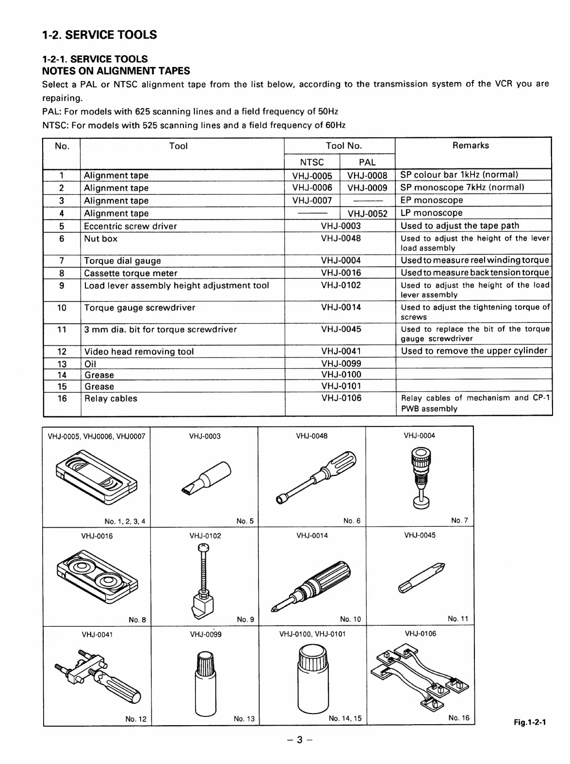
1-2.
SERVICE
TOOLS
......cceseceeeeeeeeeeee
3
MECHANISM
uu...
.ececescseseseseeceeceeeee
16
ASSEMBLY
POSITION
AND
2.
AN
OVERVIEW
OF
THE
3-10.
L
GUIDE
LEVER
ASSEMBLY
AND
CHECKING
THE
BACK
TENSION
MECHANISM
LOAD
LEVER
ASSEMBLY
.............
18
TORQUE
IN
PLAY
MODE
..............
27
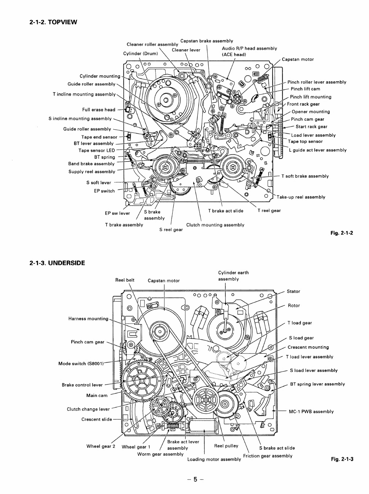
2-1.
NAMES
OF
THE
MAIN
PARTS
.......
4
3-11.
BT
LEVER
ASSEMBLY
..........00000-
18
4-3.
TAPE PATH
ADJUSTMENT
..........
28
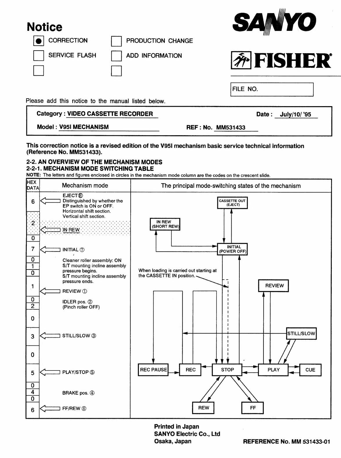
2-2.
AN
OVERVIEW
OF
THE
3-12.
REEL
DRIVE
MECHANISM
............
19
MECHANISM
MODES
............00000-
6
B13.
BRAKES
citctacsicsGearasscoreentienttitedeess
20
3.
DIS-ASSEMBLING
THE
MAIN
STS
GUIDES
swetesntadesatissonehtonssseeitencciaags
22
PARTS
OF
THE
MECHANISM
3-15.
WHEEL
GEAR
2,
MAIN
CAM
AND
3-1.
HOW
TO
MAKE
THE
MECHANISM
MODE
SWITCH
......ccseseeeeeeeeeeeeee
23
MOVEx
ea
etn
tarot
8
~°
3-16.
CRESCENT
SLIDE
uc
24
3-2.
MECHANISM
UNIT
ou...
cece.
9
3-17.
S
LOAD
GEAR,
T
LOAD
GEAR,
3-3.
CASSETTE
DRIVE
MECHANISM
....9
S
LOAD
LEVER
ASSEMBLY
AND
3-4.
CLEANER
ROLLER
T
LOAD
LEVER
ASSEMBLY
..........
25
ASSEMBLY
..u.cicecesescscsscseeeeseeeeeees
11
3-18.
TAPE
SENSORS,
REEL
SENSOR
3-5.
CYLINDER
(DRUM)
uu...
eee
12
AND
EP
SW
LEVER
....eeceeceeeeees
26
3-6.
FE
HEAD
AND
ACE
HEAD..............
14
V
MECHANISM
REFERENCE
No.MM531433