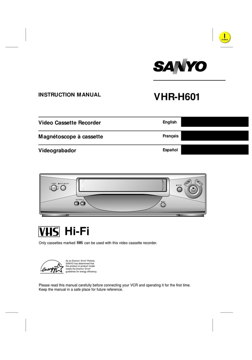
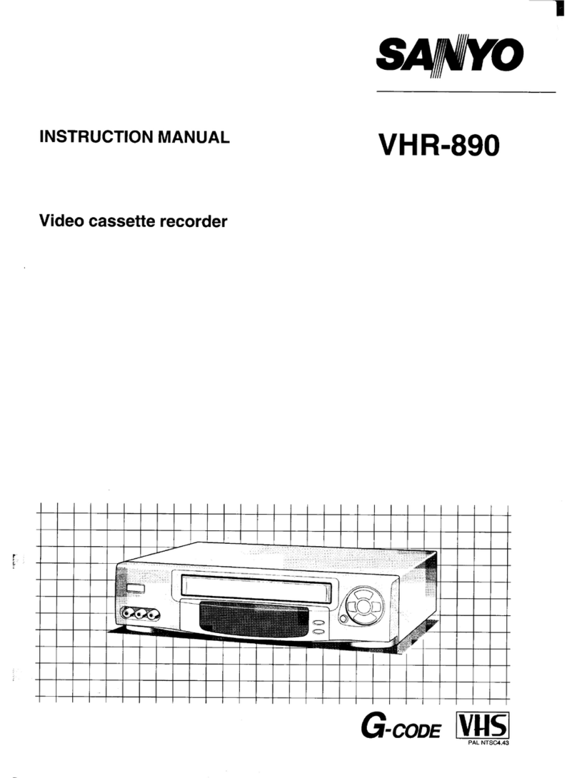
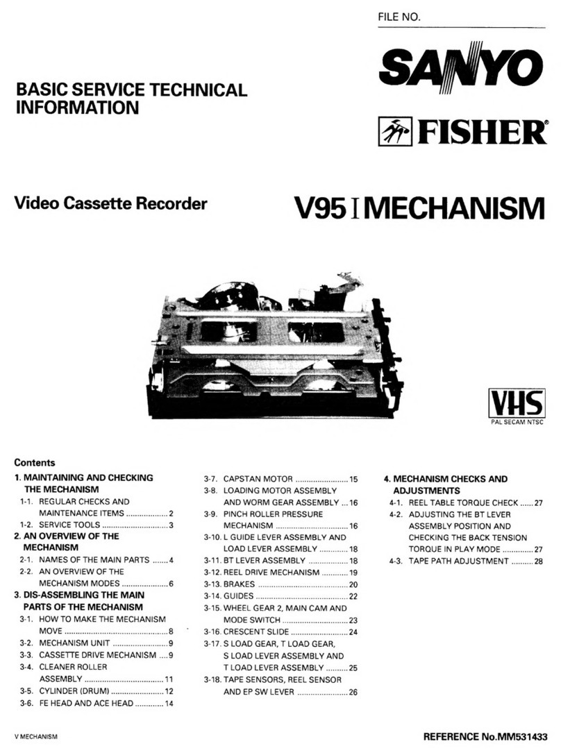
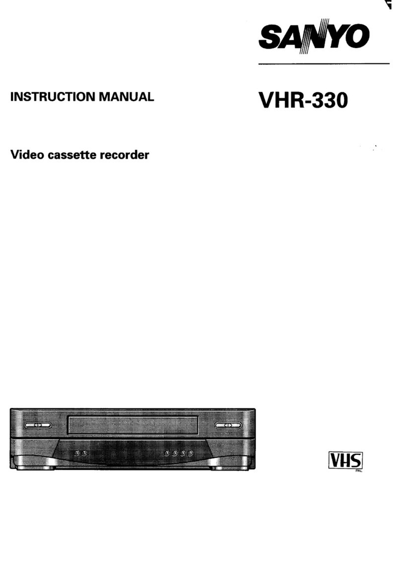
Sanyo VHR-330EV User manual

IFILE NO. I
Service Manual Video Cassette
Recorder VHR-330EV
(Switzerland &Austria)
VI+ R-330ES (Northern Europe)
VHR-330 (New Zealand)
liiriq
PAL
CONTENTS
1.
2.
3.
4.
DISASSEMBLY .....................................2
ELECTRICAL ADJUSTMENT .........................6
TEST POINT FOR TAPE PATH ADJUSTMENT . . . . . . . . . 14
PARTS LIST
ACCESSORIES ................................... 15
PACKING MATERIALS .............................15
CABINET &CHASSIS PARTS .......................15
MECHANISM PARTS .............................. 16
ELECTRICAL PARTS ..............................19
CIRCUIT DIAGRAMS (Refer to the separate volume)
PRODUCT SAFETY NOTICE
The components designated by a symbol ( ~ ) in thisschematic diagram designates com-
ponents whose value are of specialsignificanceto product safety. Should any component
designated by a symbol need to be replaced,use only the partdesignated in the Parts List.
Do not deviate from the resistance,wattage and voltageratingsshown.
NOTE: 1. Parts order must contain Model Number, Part Number and Description,
2. N.S.P.:Not available as service parts.
Please see other materials with Reference
No. given in table below.
Materials Model No. Reference No.
P90
Mechaniam Mechanism WM-530599
Manual ’92‘d ‘dMount MS 531206
Mechamsm
TP27EV, ES, NZ 14314264,96, 54 REFERENCE No. SM531246

M1-14207(1) 1/3
1. DISASSEMBLY
1-1.REMOVAL OF CABINET, MECHANISM UNIT AND MAIN BOARD
REMOVING THE CABINET PARTS (Fig. 1.1.1) REMOVING THE CP-I PWB ASSEMBLY (Fig. 1.1.3)
1. Remove the cabinet and bottom cover by removing the After removing the cabinet parts and mechanism unit:
four screws (A) and five screws (B). 1. Pull outthe TM-1 PWBAss’yfrom CN301 and CN302while
2. Remove the front panel by removing the locks of the pressing and spreading out the four clamps (H).
clamps (C) using ascrewdriver, etc. and slightly rotating 2. Remove theholdersettothe opening of thechassis, while
the bottom part in the direction of the arrow. pressing the clamp in the direction of the arrow.
NOTE: Electrical adjustments for the this model can be 3. Remove the two red screws (J). Next, remove the CP-1
performed with only the cabinet removed. PWB Ass’y by lifting it straight up while pressing and
spreading out the two clamps (K).
REMOVING THE MECHANISM MAIN UNIT (Fig. 1.1.2)
After removing the cabinet parts:
1.
2,
3.
Remove the two screws (D), and then remove the bracket.
Remove the 29-wire flat cable from the MC-2 PWB, and
then remove the 1l-wire flat cable from the VP-1 PWB
Ass’y.
Remove the mechanism main unit by removing the two
screws (E) and two screws (F).
Remove, as well, the two screws (G) at the cassette tray
side while pressing the tray lock lever as shown in the
enlarged view arrow to remove the lock and pushing the
cassette tray to the position where the two screws (G)
appear.
.
M-TEIIJE-1
Front Panel nit
ver
,,. ,.. ,
,!
Fig. 1.1.1 w

M-TP4/lR-2
,, ::; ,.,, ., -i
ff@)
Tray Look Lever able
Ca
Fig. 1.1.2
M.TPUIR-3
,..~<;. . ..
<,,
tteHolder
Mechanism Main Unit
PWB
Cable
!..
Cp-1 PWB ASS’Y
Clamps(K1
Chassis
TM.+DWR A..I.
!.., ,. ..”ruijy
29-wireFlatCable
Line
.&Ho’de’
Wlv Opening
Clamps
Fig. 1.1.3 1
–3–

M1-14207(1) 3/3
TEMPORARILY SEITING UP AND CONNECTING MAIN PWB ASSEMBLY
The following is an example of how to place and connect the main PWB not requiring ajig, when repairing the
CP-I PWB assembly H9.I .1.4)
1. Place themechanismmain unit atthefixed position forthe
chassis.
2. Connect the 29-wire flat cable to the MC-2 PWB ,and the
1l-wire flat cable to the VP-1 PWB Ass’y respectively.
Connect the TM-1 PWB Ass’y if necessa~.
3. Place the CP-I PWB Ass’y on top of the mechanism main
unit along the cassette holder. Insert the tip (L) of the
terminal board into the opening (M) at the side of the
chassis, as shown in the enlargement diagram to stabilize
the CP-I PWB /ks’Y.
M-TP4/l R-4
11-wireFlatCable —.
+(, -.,
I
CP-1 PWB Ass’Y
dFat:JI/cp-’’w
Tip(L)
Cassette Holder
\
Opening (M)
W&y /
MC-2 PWB
Fig. 1.1.4
.-
–4–

d
L1 14264(N) 1/1
1-2. MAIN CIRCUIT BOARD LOCATIONS
L-TP4/l R(21)
/----- Vp- 1PWB /%S’y
Shield Case
‘powers”pp’ypa”’~*~ MC-2 PWB
r
(On the Mechanism
TM-1 PWB~
c.-5m& \ / c“convener
\y/L’:uneruni’
Illustration :VHR-330E9VHR-330
L-TP4(G
~VP-1 PWB Asssy
rMC-2 PWB
(Onthe Mechanism
~RF Converter
Shield Case
‘powers””;---+ /\ ,
TM-8 PWB
Lq a&$
0
/
\
0
‘. .
#/
TM-1 PWB -.-/
Illustration :VHR-330EV
Unit)
Unit)
Fig. 1.2.1
–5–

S1 14229(N) 1/2
2. ELECTRICALADJUSTMENT —
PREPARATION
This VCR need 4basic presetting by using the menus displayed on-screen.
After all connection have been made, then follow steps 1to 4to preset the VCR.
The 4presetting steps will be displayed in sequence on TV screen. The setting are entered with the remote control.
Turn on the VCR
1. Adjusting the TV receiver to the video channel; The WELCOME screen will appear. When the video channel has been preset,
press the OK button on the remote control.
2. Language selection: Select the desired language, then press the OK button.
3. Clock setting: Using the remote control numeric buttons, enter the date and time, press the OK button.
4. Tuning control adjustments: When the channel position has been preset, press the MENU~ button.
When steps 1to 4have been finish, ready to operate the all operating mode.
2-1. SERVO CIRCUIT ADJUSTMENT
,These adjustments should be carried out upon completion of the tape transport adjustments.
●If the tape transport adjustments (except the tilt adjustment) are carried out after these adjustments, follow the procedures
again in Section 2-1-3. SWITCHING POSITION ADJ.
●When acassette tape is loaded, auto-tracking will be set immediately after starting the first playback. As this will deviate the
tracking center set, be sure to press the channel buttons (+) or (-) once directly after starting playback to prevent auto-tracking _
from being set,
2-1-1. TEST EQUIPMENT AND STANDARDS REQUIRED
Oscilloscope Vertical sensitivity: 5mV/DIV, external trigger
Band width: more than 10 MHz
Test Tape VHJ-0009 or VHJ-0023: SP mode, monoscope, 6KHz
IBlankTape IVHS-type cassette tape I
IMonitorTV I I
2-1-2. LOCATION OF ADJUSTMENT POINTS
PlB08300F-Sl/l r
‘Q
uo
~.;.’...,
$..
.....’
1IC602
..............
.............. 0
TM-8 PWB IC301 c)
IC351
u
IF Unit
.......
:~
::
::
:. {
>
O’yj‘if j’o ,!C16-’! Q“‘~:~r
...................____ ....................
T%? >(~~p1020[9j(~’’9”;:’\
VIDEO CT321 VRI03 VRIOI .....................
OUT Vco
CP-I PWB (FOIL SIDE) Fig. 2.1.1
“b
-
–6–

F,?,# “..~i>;‘i: ..-’”..“
‘“
“-’.?“.. . . ..;. .
3$,. ~.* ~,. ,-
S114264(NI 2/2
PlS08600C-Sl
Shield Case
.
0
‘J\]
u@
.- 0
.——
TP181
Recurrent
TP183 SW-P VR182RECYIC
TP182 ENV
;,
VP-1 PWB ASS’Y Fig. 2.1.2
NOTE:
.Self-recording means “Record any broadcasting or video
ksignal and play back the just-recorded portion”.
2-1-3. SWITCHING POSITION ADJ.
Measuring Point Measuring Equipment ADJ. Condition
TPIOI Oscilloscope PlAY(SP)mod5
(VIDEO OUT) Test tape
TP183 (SW-P) (VHJ-0009 or
VHJ-0023)
ADJ. Location ADJ.Value
\VR351 (SW-P) /6.5 Hf0.5H I
1. Set the tracking control position to the center by pressing
CHANNEL buttons (+) and (-) simultaneously.
(Tracking center position display in the indicator
panel “T -:- “)
2. Adjust VR351 (SW-P) so that the width “T”becomes 6.5 H
~0.5 Has shown in Fig. 2.1.3.
WFS101
T=6.5H f0.5H
vertical sync signal
tt
Rise RF. SW. PULSE
2
Fig. 2.1.3
2-1-4. STILL V-LOCK ADJ.
Measuring Point MeasuringEquipment ADJ. Condition
Picture of Color bar generator Self-recording
monitor TV or (SP mode)
Broadcasting STILL mode
Monitor Blank tape
ADJ. Location ADJ. Value
CHANNEL (+) button
CHANNEL (-) button The minimum vertical shake
1. Play back the just-recorded portion and then set the VCR
in the STILL mode.
2. Press the CHANNEL(+) button orthe CHANNEL (-) button
so that any vertical shake of the picture is brought to its
minimum.
-7–

VI 14208(N) 1/4
2-2. VIDEO CIRCUIT ADJUSTMENT
.Before making the following adjustments, Section 2-1. SERVO CIRCUIT ADJUSTMENT should be completed.
.Use the relay jig to provide simde adjustment of the VP-1 PWB Ass’y.
2-2-1. TEST EQUIPMENT AND STANDARDS REQUIRED
Color Bar Signal Generator
‘-n
PAL Color barsignei with 100% white level (EBU color barsignel)
(Signal waveform is described below. Refer to Fig. 2.2.1)
Oscilloscope Vertical sensitivity: 5mV/DIV, external trigger
Band width: more than 10 MHz
Digital Voltmeter DC range
Test Tape VHJ-0008 or VHJ-0023: SP mode, color bar, lkHz
(Color bar signal waveform is described below. Refer to Fig. 2.2.3)
Blank Tape VHS-type cassette tape -”
—I I
IOscilloscope Probe IInput capacity: less than 25 pF (10:1) I
less than 40 pF (1:1)
Covering frequency: DC -40 MHz (10:1) :X/l
.
DC-30 MHZ(I:I)
Frequency Counter 8significant digits
Adjustment Relay Jig VHJ-0065: 5-wire flat cable for VP-1 PWB Ass’y
.—
PAL TV TEST SIGNAL
WPVSCS 9
—
bitePeak
Iv Pedestal
Sync Tip
Level
Level
Level
1.S”C251
COLOR BAR SIGNAL WAVEFORM Fig. 2.2.1
COLOR BAR PAITERN MONITOR TV Fig. 2.2.2
WPV.TCS m
White
,
Iv
Vp-p
‘H.Sync Signal
COLOR BAR SIGNAL WAVEFORM (VHJ-0008)
Fig. 2.2.3
COLOR BAR PATFERN (VHJ-0008) ON MONITOR TV
Fig. 2.2.4
......”..
–8–

VI 14264(N) 2{4
2-2-2. LOCATION OF ADJUSTMENT POINTS
Iclol
c)
o
PI B08800C VI
Shield case
o
IF “
+
-- 0
.—— .,. ,
TP181
REC Curren
TP183 SW-P VR181 REC-Y/C
TP182ENV
VP- IPVW3 ASS’Y Fig. 2.2.5
PlBo8300F-vl/l
t
~
‘()
uo
~\
,.,
:.,“...
c)
o
...,,.
...
IC602
.............. 0
..........- .... IF Unit
TM-8 PWB IC351 r------
IC301
oVR351 i----- ; ;
Sw-p :,~.; : ;
QVR201 ; ;
~!A+s .......
n
;el
IC201 ....0
TP202 ;----~
●::
TP;oI ~ ~
::
... ::
:: ::
VR 104
05 ~~ J
TP321
>TPI02 Q’j+@;,@;,!dO TPI03 .....................
TP1OI .@! 4X
VIDEO cf321 VRI03 VR101 .....................
OUT Vco CAR PB-Y
CP-I PVVB (FOIL SIDE) Fig. 2.2.6
r’-’-: Icl11
:...:
–9–

V1-14207(1) 314
2-2-3. ADJUSTMENT RELAY JIG
Connect the Flat cable end from the Cylinder Ass’y to the
VP-1 PWBAss’yusingthe Relay jigtoprovidesimple repairing
and adjustment of the VP-1 PWB ASS*Y,as shown in Fig. 2.2.7.
Further, when adjusting the VP-1 PWB Ass’y, be sure to make
contact an end of Shield case with Bracket of the VP-1 PWB
Ass’yto maintain the shield effect. lfthe VP-1 PWBAss’ydoes
not contact, there is insufficient ground and no proper play
back image can be obtained.
wPv-TP4/lR vp-1 PWB ASS’Y
0
c\
\
Relay Jig o
~%
u
Flat Cabl ~“
Ass8y CG \
Cylinder
00
Fig. 2.2.7
NOTES:
.Self-recording means “Record the video signal and play
back the just-recorded portion”.
.Connect the monitor TV to the VIDEO OUTPUT terminal
(EURO-AVterminal pin 19), before making following ad-
justments.
2-2-4. AGC LEVEL ADJ.
Measuring Point Measuring Equipment ADJ. Condition
TPI02 Color bar generator E-E mode
Oscilloscope
(10:1 probe)
ADJ. Location ADJ. Value
VRI02(AGC) 0.5vpp k0.025vp-P
1. Connect the color bar generator to the VIDEO INPUT
terminal (EURO-AV pin20).
2. Adjust VR102 (AGC) forO.5Vp-pt 0.025Vp-passhown in
Fig. 2.2.8.
WPV-AGC 100?4. white
fI
b
0.5 Vp-p50.025Vp-p
!-r
,
Fig.2.2.8
2-2-5. PB-Y LEVEL ADJ.
Measuring Point
TPIOI
Measuring Equipment
Oscilloscope
ADJ. Condition
PLAY(SP)mode
Test tape
(VHJ-0008 or
VHJ-0023)
11I
ADJ. Location ADJ. Value
VRIOI (PB-Y) 1Vp-p f0.05 Vpp
1. Play back atest tape in SP mode.
2. Adjust VRIO1 (PB-Y) for the video luminance signal level
of 1Vp-p t0.05Vp-p. (Refer to Fig. 2.2.9)
WFV109 0% white
1Vp-p
1
I.-k-.--u u
k--- IH <.9.2.,.,
2-2-6. CARRIER SET ADJ.
~
Measuring Point MeasuringEquipment ADJ. Condition
II
ADJ. Location ADJ. Value
\VRI03(CAR) I3.83 MHz t0.05 MHz \
-
1. Connect the color bar generator to the VIDEO INPUT _
terminal (EURO-AV pin 20).
2. After removing the first color bar signal input from the
video input terminal, immediately adjust VRI03 (CAR) so
that the frequency becomes 3.83 MHzt 0.05 MHz.
2-2-7. VCO (on screen assist) ADJ.
MeasuringPoint Measuring Equipment ADJ. Cond@ion
TP321 Color bar generator E-E mode
Digital voltmeter
ADJ, Location ADJ. Value
CT321(VCO) 2.5 VP-Pk0.3 vpP
1. Connect the digital voltmeter (DC range) to TP321 and
GND.
2. Adjust CT321 (VCO) so that the voltage is 2.5 Vt0.3 V. -
—
-lo–

V1-14264(N) 4J4
2-2-8. DEVIATION ADJ.
+Ihbasurinqpoint lMeasuringEquiprnent lADJ.Ccmdition I
VR104 (DEV) 1Vp-p i0.05 Vpp I
1. Record the color bar signal on the blank tape.
2. Play back of the just-recorded portion.
3. Adjust VR104 (DEV) for 1Vp-p ~0.05Vp-p as shown in
Fig. 2.2.10.
4. If the adjustment value is not satisfactory, adjust VR104
(DEV) and repeat steps 2to 3.
WPV-DEV
White
1Vp
L,H—l
Fig.2.2.10
2-2-9. Y/C REC CURRENT ADJ.
Measuring Point Measuring Equipment ADJ. Condition
TP181 Color bar generator REC(SPknode
(on VP-1 PWB) Oscilloscope Blank tape
(1:1 probe)
ADJ. Location ADJ. Value
VR182 (REC-Y) ForVHR-330EVNHR-330 ES:
600 mVp-p t25 mVp-p
For VHR-330:
550 mVp-p t25 mVp-p
1. Connect the ground of the oscilloscope to the shield case
of the VP-1 PWB Ass’y.
2. Adjust VR182 (REC-Y) so that the video luminance
signal level at the sync tip is Model VHR-330EV/
VHR-330ES: 600 mVp-p t25 mVp-p, Model VHR-330
550mVp-p t25 mVp-p. (Refer to Fig. 2.2.1 1)
WYREC
f
VHR-330EVI
VHR-330ES:
600 t25 mVp-p
VHR-330:
550 *25 mVp-p
——
Sync Tip
Fig. 2.2.11
.-
. .
–11–

A1-14229(N) 1/2
2-3. AUDIO CIRCUIT ADJUSTMENT
●Before making these adjustments, (especially, the tape
guide height and audio control erase head height adjust-
ments) should be carried out, so that the tape traveling
between the loading guide pole and the audio control
erase head runs without fluttering, twisting, curling.
2-3-1. TEST EQUIPMENT AND STANDARDS REQUIRED
.Before making these adjustments, Section 2-1. SERVO -
and Section 2-2. VIDEO circuit adjustments should be
carried out.
Output frequency
Output level
Output impedance
Distortion ratio
Output in use SG
:10 Hz -20 kHz
:more than 1Vrms
:600 Q
:less than 0.1%
:Frequency: .................. 1kHz, 10 kHz (switchable)
Output level: ................-33.8 dBs ~0.5 dB
Standard Audio Signal Generator
Color Bar Signal Generator Color bar signel with 100?4owhite level.
(Signal waveform is described before. Refer to Fig. 2.2.1)
Oscilloscope Vertical sensitivity :10 mV/DIV
Band width :more than 30 MHz
AC Vo Itmeter Effective value indication
Input frequency :10 Hz -20kHz
Input Impedance :more than 1MC?
Measurement level :1 mV (full scale)
Blank Tape VHS-type cassette tape
2-3-2. LOCATION OF ADJUSTMENT POINTS
PlB08300F-Al/l
‘n uo 0 d’
...
:..,,..u
:.
‘../
IIC602 af
I........... ... </ IF
VR351 ~---:
SW-P ‘~.’
.............
T;M-8 PWB IC30’ IC351
oQVR201
BIAS ...
Iclol
c1
o
IC201 nTP202 ;...
●:
TP;Ol~
..
.....
u
IC302
VR 104
IC321
o~
TP321
>TPI02
TPIOI {9;
VIDEO CT321
(3UT Vco
VRI02 DEV :
/’0 Tuner
AGC IC161
+Unit
............
............
a);~:[~j{~;;{;;; OTPl 03 ...............
4~RF Conv. j
....................
VRI03 VRIOI
CAR PB-Y
C....-
CP-1 PWB (FOIL SIDE) Fig. 2.3.1
–12–

A1-14207(1) 2/2
NOTE:
.Self-recording means “Record the audio signal and play
back the just-recorded portion”.
2-3-3. BIAS LEVEL ADJ.
[Al
Measuring Point Measuring Equipment ADJ,Condition
TP201(HOT) Oscilloscope REC (SP) mode
TP202 (GND) AC voltmeter Blank tape
ADJ. Location ADJ. Value
VR201 (BIAS) 23 mVrms
1. Load the VCR with a blank tape and select the SP record
mode without all incoming signal.
2. After confirming on the oscilloscope that a 70 kHz sine
wave is being output, adjust VR201 (BIAS) sothatthe AC
Lvoltmeter’s reading is23 mVrms.
[B]
Measuring Point IMeasuring Equipment IADJ, Condition
AUDIO OUTPUT Oscilloscope Self-recording
terminal AC voltmeter (SP mode
(EURO-AV pin 3: Standard audio signal Blank tape)
Lch) generator (SG:signal
-33.8 dBs, 1kHz
-33.8 dBs, 10 kHz)
ADJ. Location ADJ. Value
VR201 (BIAS) -4 dB -+4dB
between 400 kHz and 10 kH;
1. Connectthestandard audio signal generatortotheAUDIO
INPUT terminal (EURO-AV pin6: Lch).
2. Set the standard audio signal generator’s output level to
-33.8 dBs.
3. Set the standard audio signal generator’s frequency to
400 Hz and then 10 kHz. Record each of these frequency
signals.
4. Play back each of the just-recorded portion.
5. Confirm that the 10 kHz level on AC voltmeter’s reading is
from -4 dB to +4 dB, compared with 400 Hz level.
6. If the 10 kHz level is less than -4 dB below 400 Hz level or
more than +4 dB above 400 Hz level, Rotate VR201 (BIAS)
slightly to adjust it.
7. Repeat steps 3through 6if necessary.
–13–

TTP3/EV(N) 1/1
2-4. TUNER AND IF CIRCUITS ADJUSTMENT
●When any malfunction occurs in the TUNER circuit the NOTE:
whole unit must be replaced.
●An adjustment of the IF circuit is shown as follows.
2-4-1. TEST EQUIPMENT AND STANDARD REQUIRED
The TUNER unit does not need any adjustments, –
because precise adjustments have been performed
before shipment.
IMonitorTV I I
2-4-2. LOCATION OF ADJUSTMENT POINT
PPCRO0580-R1
Tuner Uni
-i!!l
VR611 RFAGC I+1
In
IF Unit+l
CP-I PWB
(PARTS SIDE)
IF UNIT Fig. 2.4.1
2-4-3. RF AGC ADJ.
Measuring Point Measuring Equipment ADJ. Condition
Picture of Monitor TV E-E mode
monitor lV
ADJ. Location ADJ. Value
VR611 (RF AGC) S/N is best point
(on the IF circuit)
1.
2.
3.
4.
Connect the monitor TVto VHF/U HFANTENNA OUTPUT 4
terminal.
Connect the VHF antenna to VHF/UHF ANTENNA INPUT
terminal.
Receive the middle electrical field (70 dB~ -90 dB@ of
the VHF high channel, and slowly turn VR611 (RF AGC)
from the point where snow-noise is present to the point
where it just disappears from the monitor TV.
Confirm bymonitor TVthat there isno beat and saturation
(S/N is best ~oint) when receiving any TV channel.
3. TEST POINT FOR TAPE PATHADJUSTMENT
Test point TP182 (ENV) and TP183 (SW-P) for tape path adjustment is shown in Figure below.
For adjustment, refer to the Mechanism Service Technical lnformation(WM-530599 and MS531206).
P1BOS800B-T3
,,
Shield Case
(~
o
‘Jn -
+
-- 0
———
TP181
REC Current
TP183 SW-P VR 182 REC-YIC
TP182 ENV
VP-1 PWB ASS’Y Fig.3.1
w
–14–

4. PARTS LIST
LOCATION PARTS NO.
LACCESSilRIES
OR
OR
OR
OR
OR
OR
A
OR A
OR A
OR A
OR A
6450022418
6450026744
613 1453227
613 149 3940
613 151 4591
613 146 4018
613 096 6773
613 011 7359
613 132 6132
613 132 5975
6130950550
613 1332393
645 0026805
645 003 3766
6450027642
DESCRIPTION
REMOCON(WITH COVER BATTERY)
(EXCEPT UHR-330)
REMOCON(WITH COVER BfiTTERY)
(VHR-330 ONLY)
COVER BATTERY(FOR REMOCON)
INSTRUCTION MfiNUAL(UHR-330EUONLY)
INSTRUCTION MANUAL(VHR-330ES ONLY)
INSTRUCTION MANUAL(VHR-330 ONLY)
CABLE,ANT
CORD
CABLE,ANT
CORO
CORD,POWER(EXCEPT VHR-330)
CORO,POWER(EXCEPT VHR-330)
CORO,POWER(VHR-330 ONLY)
PACKINGMATERIALS
L613 14? 8471
OR 613 151 5529
OR 613 1494336
613 144 5802
OR 613 1502277
613 144 5819
OR 613 1502284
613099 1768
CARTON CASE(VHR-330EV ONLY)
CARTON CASE(VHR-330ES ONLY)
CARTON CASE(VHR-330 ONLY)
CUSHION,FRONT(EXCEPT VHR-330)
CUSHION,FRONT(VHR-330 ONLY)
CUSHION,BACK(EXCEPT UHR-330)
CUSHION,BACK(VHR-330 ONLY)
POLYE COVER,INNER-K
***** *%**%****$*******%****************************************
Undesignated numeral shows
Location No.: CH-
N.S.P.:Not availableas service parts
V-3 7
2- “
L
LOCATION PfiRTSNO.
CABINET&CHASSISPARTS
CH-1
CH-2
CH-3
CH-4
CH-5
CH-6
CH-7
OR
OR
OR
CH-8
OR
CH-9
CH-10
CH-11
OR
OR
CH-12
OR
CH-13
OR
CH-16
CH-17
CH-19
CH-20
CH-21
OR
CH-22
CH-23
OR
CH-24
411 137 0007
411 021 7907
411 027 1701
613 1464988
412028 9406
613 1407015
613 143 8644
613 1438651
613 1354739
613 135 4753
613 144 1453
613 1479906
411 021 3800
613 134 4730
613 149 6026
613 151 6410
613 1495210
613 1079410
613094 4429
613 135 7891
6130944436
613 1450707
613 1392182
613 121 1001
613 1444461
613 1498846
613 151 0111
613 140 7459
613 1460447
613 1483286
613 741 1395
DESCRIPTION
SCR L-TPG BIN 3X1O
SCR S-TPG BIN 4X12
SCR S-TPG BIN 3X1O
COMPL PWB,VP-1
SPECIOL SCREW
COVER TOP
MOOULATOR,RF(EXCEPT VHR-330)
MOOULATOR.RF(EXCEPT VHR-330)
MOOULATOR}RF(VHR-330 ONLY)
MOOULATOR,RF(VHR-330 ONLY)
TERMINAL(EXCEPT VHR-330)
TERMINAL(UHR-330 ONLY)
SCR S-TPG BIN 3X1O
COMPL PCB.TM-8(VHR-330EV ONLY)
COMPL PWB,CP-1-A(VHR-330EV ONLY)
COMPL PWB,CP-1-A(VHR-330ES ONLY)
COMPL PWB,CP-1-A(VHR-330 ONLY)
TUNER PACK(EXCEPT VHR-330)
TUNER PACK(VHR-330 ONLY)
IF PACK(EXCEPT VHR-330)
IF PACK(VHR-330 ONLY)
STANO,BACK
COVER BOTTOM
STANO,FELTrFRONT
COMPL PWB,TM-1
000R CASSETTE(VHR-330EV ONLY)
000R CASSETTE(EXCEPT VHR-330EV)
SPRING
ASSY,CABINET
ASSY,CABINET
PLUG,26P
FRONT(EXCEPT VHR-330)
FRONT(VHR-330 ONLY)
11.
–15–

MECHANISM PARTS
LOCATION PARTS NO. DESCRIPTION
MECHANISMPA> ~ ($/3 - [5D -7(66
OR-1
OR
DR-2
* DR-3
OR-4
OR
OR-5
OR-6
OR-7
DR-8
DR-9
OR
DR-10
OR
DR-11
DR-12
MB-1
MB-2
MB-3
MB-4
MB-5
MB-6
MB-7
MB-8
MB-9
MB-10
MB-11
MB-12
MB-13
MB-14
MB-15
MB-16
MB-17
MB-18
MB-19
MB-20
MB-21
MB-22
MB-23
MB-24
OR
MB-28
MB-29
MB-30
MB-31
MB-32
MB-33
MB-34
MB-35
MB-36
MB-37
MB-38
MB-39
MB-40
MB-41
MB-42
MB-43
MB-44
OR
MB-45
MB-46
MB-47
MB-48
MB-49
tlB-50
MB-51
L
613 113 1323
6130788665
411 038 1608
613 113 1354
6130220271
6130972170
6130889072
411 047 7509
411 047 5000
613 085 727?
613 1323520
411 044 8301
411 044 9209
6130224019
411 044 9001
613 123 4802
613053 3227
613 1234970
411 0045302
613 1239418
613021 9961
613021 9800
411 1092008
613022 1797
613 1445741
613 110 1692
4120158207
411 1200007
613 1203631
613022 1582
613094 9240
613022 1575
6130222725
6130222534
613094 1206
613 134 2910
411 0468002
411 0232801
411 0233303
411 021 3107
613 077 3227
6130270382
6130788320
613 1170599
6130939159
6130938374
613077 3616
613 121 9960
6130929945
613 1328075
613 1438439
613 110 0374
411 126 5303
6130929921
6130925985
6130925992
6130925886
613 1388628
613027 0627
6130929938
6130222985
4120334106
6130773579
613 1029293
cotlPL,cYLINDER,2N2P-v
COMPL,CYLINDER,2N2P-V
SCR PAN+W 3X8
OSSY,CYLINDER,UPR 2N2P-V
ASSY,CYLINOER,LWR 2AL
ASSY,CYLINDER.LWR 2
SPACER,MOTOR 0.3T
BASE,CYLINDER
SCR PAN+FLG 3X6
SCR Pf-lN+FLG2.6X8
STATOR,MOTOR CYLINDER
SCR PAN+SW 2.3X1O
SCR PCiN+SW2.3X8
ROTOR,MOTOR CYLINDER
SCR PAN+SW 2.3X6
SLEEVE
SPECIAL WASHER
TAPE GUIDE
NUT HEX (3)
CAP
6SSY,SLIDE,ACT PINCH
ASSY,LEVER,CAM PINCH
WASHER Y 3.1X8X0.5
SPRING,ACE HE(ID
COMPL,BRACKET,HEAD
SLEEVE,ACE HEAD
SPECIAL NUT (M5)
SCR PAN+SW+W 2.6X5
BRACKET,STOPPER
SPRING,SLIDE BRAKE
COMPL,SLIDE,CAM
SPRING,LINK LOCK
DAMPER
GEAR.FRONT LOf)O
ASSY,LEVER,FRONT
GEAR,HELICAL FRONT
SCR PAN+SW+W 2.6X6
SCR .S-TPCIPAN 2.6X6
SCR S-TPG PAN 2.6X8
SCR S-TPG BIN 2.6X8
HOLDER,WORM
WASHER
ASSY,WORM,FRONT
BRACKET,HOLDER
PLATE,NUT
DAMPER,MOTOR
DAMPER,WORM
OSSY.LOADING MOTOR
CIIMPER,MOTOR
COMPL PCB,MC-3
COMPL PWB,MC-2
ROTARY SWITCH
SCR PAN 2.6X13
ASSY,SLIDE,FRONT
SPRING,LEVER LOAD
SPRI.NG,LEVER ACT
HOLDER,WORM
HOLDER,WORM
WASHER 2.1X6X0.5
ASSY,WORM,LOAD
BELT,LOADING
WASHER SLIT 2.6X5X0.50
GEAR,HELICAL
ASSY,LEVER,REV GUIDE
613022 1568 SPRING,REVIEW LEVER
DB801OOO
LOCATION PARTS NO. MBoo34##
DESCRIPTION
MB-52 6130220158 COMPL,PINCH ROLLER
MB-53 613 1479951 SPRING,PINCH ROLLER
MB-54 411 1092107 WASHER Y 3.6X6X0.5
Note:
As shown in the figure,the partssupportingthe “ASSY, GUIDE,
ROLLER” of LocationNo. MB-61 comes in two types-group A and
group B.(LocationMB-60 and 61 arethesame.)No one patiofgroup
A can be replacedby thatofgroup B by itself,but group A and group
B can be replacedas a whole as they are interchangeable.
MB-55 6130788160 COMPL,LEVER,ACT BRAKE
MB-57 613 13S 7655 PLATE,BGR
MB-58 613 1455009 ASSY,MOUNTING,ROLLER S
MB-59 613 1455016 ASSY,MOUNTING,ROLLER T
MB-60 411 0630904 SCR SET HEX-SCT 2X3
MB-61 6130220233 ASSY,GUIDE,ROLLER
MB-63 6450002533 HEAD,FULL ERASE
MB-66 613 1360532 LEVER,FE HEAD
MB-67 613022 1698 SPRING,ERASE HEAD
MB-70 613 022 1919 PLATE,GUIDE
4!B-71 411 031 1209 SCR BIN 2.6X5
MB-72 613021 9725 ASSY,BASE,ROLLER S
MB-73 613021 9732 ASSY,BASE,ROLLER T
MB-80 411 109 1803 WASHER Y 2.6X6X0.5
MB-81 613 1198562 ASSY,ROLLER,CLEANER
MB-82 613 143 1881 ASSY,LEVER,CLEANER
MB-83 613 1198593 SPRING
MB-84 613 1429055 BRACKET,CLEANER
MB-90 613 1444577 FLEXIBLE FLAT CABLE,CN811-CN303
******%****************************%****%************%****%****
MECHANISMPARTS2
MC-1
MC-2
MC-3
MC-6
MC-7
MC-8
MC-9
MC-10
MC-12
MC-13
MC-14
MC-15
MC-16
MC-17
MC-18
MC-19
MC-20
MC-22
MC-23
MC-24
MC-25
MC-26
MC-27
MC-28
MC-29
MC-30
MC-31
MC-34
MC-35
MC-36
MC-37
MC-38
MC-40
MC-41
6450005053
6130222978
613 1354609
613022 1520
6130823434
613022 1711
613081 7518
6130982285
411 021 3107
411 1092008
613 1429093
6130222701
411 109 1902
613 1357686
613 1357532
411 109 1803
613 135 7648
411 0476809
613021 9763
613 1357662
613022 1551
613021 9879
6130906373
613022 1704
613021 9862
6130222039
613091 3104
411 0286309
4120158603
613 1309890
4120454606
411 0920906
411 1000300
613 1209060
MOTOR,CAPSTAN DC 3W
BELT,REEL DRIVE
COMPL,LEVER,CLUTCH
SPRING,LEVER CLUTCH
LEVER,CHANGE CLUTCH
SPRING,CHANGE CLUTCH
ASSY,BRAKE CAPSTAN
SPRING,CAPSTAN
SCR S-TPG BIN 2.6X8
WASHER Y 3.1X8X0.5
SLIDE,CAM PLATE
CAM,MODE
WASHER Y 3.1X6X0.5
CAM,MAIN
ASSY,RACK,LOAD
WASHER Y 2.6X6X0.5
SPACER.RACK LOAO
SCR PAN+FLG 3X4
ASSY,EARTH,CYL
GEAR,LOAD TAKE UP
SPRING,GE/lRLOAD T
ASSY,LEVER,LOAD T
GEAR,LOAD S
SPRING,GEAR LOAO S
ASSY,LEVER,LOAO S
LEVER,RETURN TENSION
ASSY,LEVER CONTROL
SCR S-TPG PAN 2.6X6
SPECIAL WASHER 3.1X6X0.25
ASSY,GEAR,FRICTION
SPECIAL WASHER 2.4X6X0.25
WASHER Z 2.6X1OXO.5
SCR S-TPG BIN 2.6X5
COMPL,MC-1
.
-
–16–

MECHANISM PARTS 1
.--,
.---, Undesignated numeral shows
ME
,.--=&DR:2 ‘“s, ‘ocatio; ‘O”: MB-
[71-+ 7,* J
:CHANISM PARTS 2
Undesignated numeral shows
Location No.:MC- ?
12-- +
N.S. P. 16+@
Ill
‘&D
12--El
40-$’ 384:
fp2
%
41- ~Q
.0 /‘
b. 00
v
4$7’
+-23
.
/
.l\ r.. .MT/ ($%&.,/”.=’J CS)-24
=27
/35
‘-k
I93TP1/Mc-l I
N.S.P.:Not available as service parts
–17–

CB602700
LOCATION PARTS NO.
MECHANISM PARTS 3
co-1
CD-4
co-5
CO-6
CD-7
CO-8
CD-9
CD-10
CD-11
CO-12
CD-13
CO-14
CD-15
CD-16
CO-17
CO-18
CO-19
CO-20
CO-21
CD-22
CD-24
CO-27
CO-28
CD-31
MA-1
MA-2
HA-3
MA-4
MA-5
MA-6
OR
MA-7
OR
613 1429581
6130220585
407 0983201
411 0159801
613022 1643
613 022 0073
613 0222695
613 141 6109
613021 9916
613 022 2626
613021 9657
411 027 1305
6130950949
411 1069208
6130220943
613022 2619
613 022 1667
613 022 2596
613022 0097
613 022 1674
613 022 4064
613 124 5006
613 1256149
411 001 8702
613 1000391
6130857996
613021 9701
411 144 2803
411 109 1605
613 1357068
613 1357549
613 1357075
613 1432963
DESCRIPTION LOCATION
COMPL,CASSETTE MECHfINIStl
LID
PHOTO COUPLE PN150SAN
RING E 2.3
SPRING,LINK L
ASSY,GEAR,LEUER L
R/ICK
GEAR,LOCK
ASSY,LEVER,PINION
GEAR,PINION
ASSY.BRQCKET,GEAR
SCR S-TPG BIN 2.6X4
SW,SPECIAL
SCR PAN+SW+W 2X9
HOLDER,TRANSISTOR
GEAR,IDLER
SPRING,GEAR MOIN
GEAR.MAIN
ASSY,GEAR,LEUER R
SPRING,LINK R
BOARD,UNDER
LEUER,SAFETY SW
SPRING,SAFETY SW
SCR BIN 3X6
ASSY,LEUER,TENSION
SPRING,LEVER TENSION
ASSY,HOLOER,BGND
SCR PAN+SW+W 2.6X6
WASHER Y 2.6X6X0.25
ASSY,REEL,SUPPLY
ASSY,REEL,SUPPLY
RSSY,REEL,TAKE UP
ASSY,REEL,TAKE UP
,.-.. -.t.. ........l..............................
I
MA-8
OR
OR
MA-9
OR
MA-10
OR
MA-11
MA-12
OR
MA-15
MA-16
MA-17
MA-18
MA-19
MA-20
MA-2i
MA-22
MA-23
MA-24
MA-25
MA-26
MA-27
MA-28
MA-29
MA-30
MA-31
MA-32
MA-33
MA-34
MO-35
MA-36
MA-37
MA-38
MA-39
----- ..........,
AA
PARTS NO.
412 021 5306
412 015 8900
4120158504
411 109 1506
411 109 1407
613 135 7150
613 1429116
412026 730S
613 1357167
613 1429109
412 042 4302
613 1357099
411 120 1301
613 135 7082
411 021 3107
613 1209053
407 016 7205
613021 9985
613 142 9086
613 022 1612
613 022 1506
613098 0106
613 077 3647
613022 1490
613022 2374
613 084 8871
613 022 0004
613080 9216
613 086 2?14
6130809209
411 1093005
6130222015
412015 9501
411 021 7907
4120454606
DESCRIPTION MBoo34#Jl
SPECIAL WASHER 3.1X6X0.3
SPECIAL WASHER 3.1X6X0,4
SPECIAL WASHER 3.1X6X0.5
WASHER Y 2.1X6X0.25
WASHER Y 2.1X5X0.25
GEAR,REEL SUPPLY
GEAR,REEL SUPPLY
SPECIAL WASHER 2.6X6X0.25
GEAR,REEL TAKE UP
GEAR,REEL TAKE UP
SPECIAL SCREW 2.6X4
COMPL,IDLER,CLUTCH
WASHER Y 2.1X4X0.25
ASSY,IDLER
SCR S-TPG BIN 2.6X8
COMPL PCB,MC-4
LED LN59
IISSY,SLIDE,ACT PLATE
SLIDE,C BRAKE
SPRING,RETURN SLIDE
SPRING,SUB T
ASSY,BRAKE SUB T
PULLEY,REEL
SPRING,SUB SUPPLY
SLIDE,ACT BRAKE
BRAKE*SUB SUPPLY
ASSY,SLIDE,M PLATE
ASSY,BRAKE,SUPPLY
SPRING,MAIN BRAKE
fISSY,BRAKE,TAKE UP
WASHER Y 2.6X5X0.5
LEVER,CONT PLATE
SPECIAL WASHER
SCR S-TPG BIN 4X12
SPECIAL WASHER 2.4X6X0.25
Undesignated numeral shows
Location No.:MA- f+j-15
5-A
6+
... .... ... .. ... .. .. .. .. .. .. .. . -------------- ......................
N.S.P.:Not available as service parts ‘=”’”
kEu!!E4 39+&
–18–

ELECTRICAL PARTS
NOTE;
1. MaterialsdCapacitwaandResiatoraareabbreviatedasfollows;
Resistors
MT-FILM MetallizedFilmResistor
MT-GLAZE MetallizedGlazaReaietor
OXIDE-MT Oxide Metal Film Resiatcx
Capacitors
MT-POLYEW Metallized PolyesterCapacitw
MT- COMPO Metallized CompositeCapacitcx
TA-SOLID Tantalum SolidCapacitor
AL-SOLID AluminumSolid Capacitor
NP-ELECT Non-PolarizedElecVolytic
Capacitcx
OS-SOLID AluminumSolid Capacitorswith
OrganicSemiconductive
ElectrolyticCapacitor
DL-ELECT DoubleLayered Electrolytic
Capacitor
2. Tolerance of Capscitor(lOPFover) and Reaiatorare noted with follow aymbolea.
F............*lo/o G............+20/0 J............*~O/o K............*10“/0
M............*20% N ............* 30% z............+800/0-–20V0
3. Capacitors
U:UF P:PF
4. Inductors
UH :uti MH :mH
5. N.S.P. :Not available aaservice parta.
LOCATION PORTS NO. DESCRIPTION
C@4PL PHB,CP-I-A
COMPL.NO 613 14? 6026 (UHR-330EU)
COMPL.NO 613 151 6410 (UHR-330ES)
COMPL.NO 613 149 5210 (UHR-330)
(SEMICiMDUCT6RS)
Q1OO2
OR
OR
OR
Q1OO3
OR
OR
OR
Q1OO4
OR
OR
OR
Q1OO6
OR
OR
OR
Q1OO7
OR
OR
OR
Q101O
OR
OR
OR
Q1011
OR
Q1012
OR
OR
OR
Q1013
OR
Q1014
OR
OR
OR
Q1101
OR
OR
4050576201
405 057 6409
405 123 7002
405 1237101
405 064 0100
405 064 0209
405 123 6708
405 1236807
405 064 0100
405 064 0209
405 123 6708
405 123 6807
405 057 6201
405 057 6409
405 123 7002
405 123 7101
405 057 6201
405 057 6409
405 123 7002
405 123 7101
405 064 0100
405 064 0209
405 1236708
405 1236807
405 063 9708
405 1236500
405 057 6201
4050576409
405 1237002
405 1237101
4050639708
405 1236500
4050576201
4050576409
405 1237002
405 123 7101
4050640100
4050640209
405 1236708
TR 2SC4038-Q-TL2
TR 2SC4038-R-TL2
TR 2SO1991rl-Q-(Tfi)
TR 2SD1991A-R-(TA)
TR 2SA1561-TL2-Q
TR 2SA1561-TL2-R -!.
TR 2SB1320A-Q-(TA)
TR 2SB1320A-R-(TA)
TR 2SA1561-TL2-Q .;
TR 2SA1561-TL2-R
TR 2SB1320A-Q-(TO) j.
TR 2SB13209-R-(Tr3)
TR 2SC4038-Q-TL2 ,,:
TR 2SC4038-R-TL2
TR 2S01991A-Q-(TA)
TR 2S01991A-R-(TA)
TR 2SC4038-Q-TL2
TR 2SC4038-R-TL2
TR 2SD199114-Q-(TA)
TR 2SD1991A-R-(TA)
TR 2SA1561-TL2-Q(VHR-330EV ONLY)
TR 2SA1561-TL2-R(VHR-330EU ONLY)
TR 2SB13200-Q-(TA)(UHR-330EU ONLY)
TR 2SB13200-R-(TA)(UHR-330EU ONLY)
TR 0TC144EL-TL2
TR UN6213-(TA)
TR 2SC4038-Q-TL2
TR 2SC4038-R-TL2
TR 2SO1991O-Q-(TA)
TR 2SD1991&R-(Tfl)
TR DTC144EL-TL2
TR UN6213-(TO)
TR 2SC4038-Q-TL2
TR 2SC4038-R-TL2
TR 2SD1991A-Q-(TA)
TR 2SD1991f%R-(Tr3)
TR 2SA1561-TL2-Q
TR 2SA1561-TL2-R
TR 2SB1320rl-Q-(TA)
LOCATION
Q1101
Q1102 ‘
OR
OR
OR
Q1151
OR
Q1152
OR
OR
OR
Q1312
OR
OR
OR
Q1313
OR
Q1601
OR
Q1653
OR
OR
OR
Q1654
OR
OR
OR
Q2001
OR
Q2002
OR
Q2003
OR
Q3001
OR
Q3002
OR
Q3201
OR
OR
OR
OR
Q3202
PORTS NO.
405 123 6807
405 057 6201
4050576409
405 123 7002
405 123 7101
405063 9906
405 1236401
4050640100
405 064 0209
405 1236708
405 123 6807
405 057 6201
405057 6409
405 123 7002
405 123 7101
4050639708
405 123 6500
405 004 4601
405 006 1806
405 057 6201
405 057 6409
405 123 7002
405 123 7101
405 064 0100
4050640209
405 123 6708
405 123 6807
4050249709
405 024 9907
405 063 9708
405 123 6500
405 003 7702
405 000 1208
4050182808
405 000 3103
405 018 2808
405000 3103
4050192005
4050192807
405011 8401
405011 8500
4050930607
405019 2005
DESCRIPTION
TR 2SB1320A-R-(TII)
TR 2SC4038-Q-TL2
TR 2SC4038-R-TL2
TR 2SD1991A-Q-(TA)
TR 2SD1991A-R-(TII)
TR DTC124EL-TL2
TR UN6212-(TA)
TR 2SA1561-TL2-Q
TR 2SA1561-TL2-R
TR 2SB1320A-Q-(TA)
TR 2SB1320A-R-(T9)
TR 2SC4038-Q-TL2
TR 2SC4038-R-TL2
TR 2SC11991A-Q-(TA)
TR 2SD1991A-R-(TA)
TR DTC144EL-TL2
TR UN6213-(TA)
TR 2SA608-F-SPA-AC
TR 2SA933S-T93-R
TR 2SC4038-Q-TL2(EXCEPTUHR-330)
TR 2SC4038-R-TL2(EXCEPTUHR-330)
TR 2SD1991A-Q-(TA)(EXCEPT VHR-330)
TR 2S01991A-R-(TA)(EXCEPT VHR-330)
TR 2SA1561-TL2-Q(EXCEPTVHR-330)
TR 2SA1561-TL2-R(EXCEPTVHR-330)
TR 2SB1320A-Q-(TA)(EXCEPT VHR-330)
TR 2SB1320A-R-(TA)(EXCEPT VHR-330)
TR 2SD734-E-AA
TR 2S0734-F-AA
TR 0TC144EL-TL2
TR UN6213-(TA)
TR 2SA1346-r3C
TR DTA124ES-DCTP
TR 2SC3402-AC
TR DTC114ES-DCTP
TR 2SC3402-AC
TR DTC114ES-DCTP
TR 2SC536-E-SP9-AC
TR 2SC536-F-SPA-AC
TR 2SC1740S-OCTP-Q
TR 2SC1740S-DCTP-R
TR KSC2785-Y
TR 2SC536-E-SPA-AC
–19–

LOCATION
Q3202
OR
OR
OR
Q3203
OR
OR
OR
OR
Q3504
OR
Q3553
OR
OR
OR
Q5101
OR
OR
Q5102
OR
OR
Q5103
OR
Q6001
OR
OR
OR
OR
OR
OR
Q6002
OR
OR
OR
OR
Q6004
OR
OR
OR
OR
Q6601
OR
Q6611
OR
OR
OR
OR
Q6621
OR
OR
OR
OR
Q6901
OR
OR
OR
OR
Q6902
OR
OR
OR
OR
Q6903
OR
OR
OR
PhRTS NO.
4050192807
405011 8401
405011 8500
4050930607
405004 4007
405004 4601
405006 1707
405006 1806
4050930508
4050639708
405 1236500
4050576201
4050576409
405 1237002
405 1237101
4050889103
405 108 7003
405 1086907
4050892103
405 107 4201
405 1074102
4050182808
4050003103
4050269004
4050269103
405 114 7806
405 114 7905
405 114 8001
405 073 6407
4050736506
405 004 4007
405 004 4601
405 006 1707
405 006 1806
405 093 0508
405019 2005
405 019 2807
405 093 0607
405 011 8401
405 011 8500
405 008 6809
405008 7103
405 004 4007
405 004 4601
405 006 1707
405 006 1806
4050930508
405 019 2005
405 019 2807
405 093 0607
405 011 8401
405011 8500
405 019 2005
4050192807
405093 0607
405011 8401
405 011 8500
405 004 4007
4050044601
405006 1707
405 006 1806
4050930508
4050192005
405019 2807
4050930607
405011 8401
DESCRIPTION
TR 2SC536-F-SPA-AC
TR 2SC1740S-OCTP-Q
TR 2SC1740S-OCTP-R
TR KSC2785-Y
TR 2SA608-E-SPA-AC
TR 2SA608-F-SPA-AC
TR 2SA933S-TP-Q
TR 2SA933S-T93-R
TR KSA1175-Y
TR DTC144EL-TL2
TR UN6213-(TA)
TR 2SC4038-Q-TL2
TR 2SC4038-R-TL2
TR
TR
TR
TR
TR
TR
TR
TR
TR
TR
TR
TR
TR
TR
TR
TR
TR
TR
TR
TR
TR
TR
TR
TR
TR
TR
TR
TR
TR
TR
TR
TR
2S01991A-Q-(TA)
2S01991A-R-(TA)
2SA1703-S-AN
2SB1322fi-S(TA)
2SB1322A-R(TA)
2SC4483-S-AN
2S01994-S (TA)
2S01994-R (TM
2SC3402-AC
OTC114ES-OCTP
2SK222-O-AA(UHR-330 ONLY)
2SK222-E-M(UHR-330 ONLY)
2SK1104-(TA) P(UHR-330 ONLY)
2SK1104-(TA) Q(UHR-330 ONLY)
2SK1104-(TA) R(UHR-330 ONLY)
2SK772-E-AC(UHR-330 ONLY)
2SK772-F-AC(UHR-330 ONLY)
2SA608-E-SPA-AC
2SA608-F-SPA-AC
2SA933S-TP-Q
2SA933S-T93-R
KSA1175-Y
2SC536-E-SPA-AC(VHR-330 ONLY)
2SC536-F-SPA-(IC(UHR-330 ONLY)
KSC2785-Y(UHR-330 ONLY)
2SC1740S-OCTP-Q(UHR-330 ONLY)
2SC1740S-DCTP-R(UHR-330 ONLY)
2SB808-F-SPfJ-AC(UHR-330 ONLY)
2SB808-G-SPA-AC(UHR-330 ONLY)
2SA608-E-SPA-AC
2SA608-F-SPA-AC
2SA933S-TP-Q
TR 2SA933S-T93-R
TR KSA1175-Y
TR 2SC536-E-SPfi-AC
TR 2SC536-F-SPFI-AC
TR KSC2785-Y
TR 2SC1740S-OCTP-Q
TR 2SC1740S-OCTP-R
TR 2SC536-E-SPA-AC
TR 2SC536-F-SPA-AC
TR KSC2785-Y
TR 2SC1740S-OCTP-Q
TR 2SC1740S-OCTP-R
TR 2SA608-E-SPA-AC
TR 2SA608-F-SPA-AC
TR 2SA933S-TP-Q
TR 2SA933S-T93-R
TR KSA1175-Y
TR 2SC536-E-SPA-AC
TR 2SC536-F-SPA-AC
TR KSC2785-Y
TR 2SC1740S-OCTP-Q
LOCfiTION PARTS NO.
Q6903 405 011 8500
Q6904 4050639708
OR 405 1236500
Q6921 4050848209
OR 405 084 8308
(INTEGRATEDCIRCUITS)
Iclol
IC1ll
IC161
OR
IC201
IC301
OR
IC302
IC303
OR
IC321
IC351
OR
OR
IC501
IC511
IC512
IC601
OR
IC602
OR
IC691
(DIODES)
D1OO3
OR
01007
OR
01601
OR
D1602
OR
01611
OR
01671
OR
03001
D3002
OR
03003
OR
03101
OR
03107
OR
03112
OR
03121
OR
03122
OR
03123
OR
03201
OR
03202
409 303 6700
4092976205
4090034501
409 1203401
4092622409
410 1740803
410 1788300
409 1144803
4092434101
4093130903
410 166 2808
4093060408
4093060507
409311 9601
4092977509
4090677203
4092977400
4090268203
4090575103
4092836905
410 172 6906
4090196209
4070079904
4070124406
4070079904
407 012 4406
4070079904
407 012 4406
4070079904
407012 4406
407070 7104
407 053 6704
407 007 9904
4070124406
407 1507703
407051 6904
407099 5303
4070708101
4070639504
407 012 4406
4070079904
4070124406
4070079904
407 012 4406
4070079904
407012 4406
4070079904
4070124406
4070079904
4070124406
4070079904
4070124406
4070079904
4070124406
DESCRIPTION
TR 2SC1740S-OCTP-R -
TR OTC144EL-TL2
TR UN6213-(TA)
TR 2SC2960-F-SPA-AC(UHR-330 ONLY)
TR 2SC2960-G-SPA-AC(UHR-330 ONLY)
IC LA7345M
IC LC89925
IC BA7021
IC LA7221
IC LA7285M
IC LC866648V-5386
IC LC866648V-5420
IC LB1641
IC MN1380-L
IC MN1381-L(TA)
IC LC74760M-8783
IC XRU2890BK
IC BU2890BK
IC BU2890DK
IC STR-M6549
IC L5431-AFI
IC PQ12SZ11
IC L5631(VHR-330 ONLY)
IC UPC574J(VHR-330 ONLY)
IC LE24C04S1
IC X24C04P-C7346
IC LA791O(VHR-330 ONLY)
OIOOE GMAO1-ET
OIOOE 1SS133-T-77
OIOOE GMAO1-BT
OIOOE 1SS133-T-77
OIOOE GMAO1-BT
OIOOE 1SS133-T-77
OIOOE GMAO1-ET
OIOOE 1SS133-T-77
ZENER OIOOE GZS5.6X-BT .-,
ZENER OIOOE MTZ5.6B-T-77
OIOOE GMOO1-BT(EXCEPT VHR-330) u
OIOOE 1SS133-T-77(EXCEPTVHR-330)
OIOOE RB441Q T-77
ZENER OIODE GZS5.6Y-BT
ZENER OIOOE MTZJ5.6B-T-77
ZENER OIODE GZS8.2Y-BT
ZENER OIOOE MTZJ8.2B-T-77
OIOOE 1SS133-T-77(EXCEPTVHR-330)
OIOOE GMAO1-BT(EXCEPT VHR-330)
OIOOE 1SS133-T-77
DIOOE GMAO1-ET
OIOOE 1SS133-T-77(VHR-330 ONLY)
OIOOE GMAO1-BT(VHR-330 ONLY)
OIOOE 1SS133-T-77
OIOOE GMAO1-BT
OIOOE 1SS133-T-77
OIOOE GIIAO1-BT
OIOOE 1SS133-T-77
OIOOE GMAO1-BT
OIOOE 1SS133-T-77
OIOOE GMAO1-ET
DIOOE 1SS133-T-77
–20–
This manual suits for next models
2
Table of contents
Other Sanyo VCR System manuals

Sanyo
Sanyo SRT-2400DC User manual

Sanyo
Sanyo VHR-420 User manual

Sanyo
Sanyo SRT-8960P User manual

Sanyo
Sanyo VHR-H803E User manual

Sanyo
Sanyo VHR-150 User manual

Sanyo
Sanyo VHR-310 User manual

Sanyo
Sanyo TLS-924 Manual

Sanyo
Sanyo VHR-489SP User manual

Sanyo
Sanyo VHR-120 Series User manual

Sanyo
Sanyo VHR-330 User manual

Sanyo
Sanyo VHR-VK310A User manual

Sanyo
Sanyo VHR-890 User manual

Sanyo
Sanyo VHR-810 User manual

Sanyo
Sanyo VHR-VK210A User manual

Sanyo
Sanyo FISHER V95 I Mechanism Manual

Sanyo
Sanyo VHR-390EX User manual

Sanyo
Sanyo VHR-650 User manual

Sanyo
Sanyo VHR-VX700 User manual

Sanyo
Sanyo VHR-510 User manual

Sanyo
Sanyo VHR-790 User manual