I
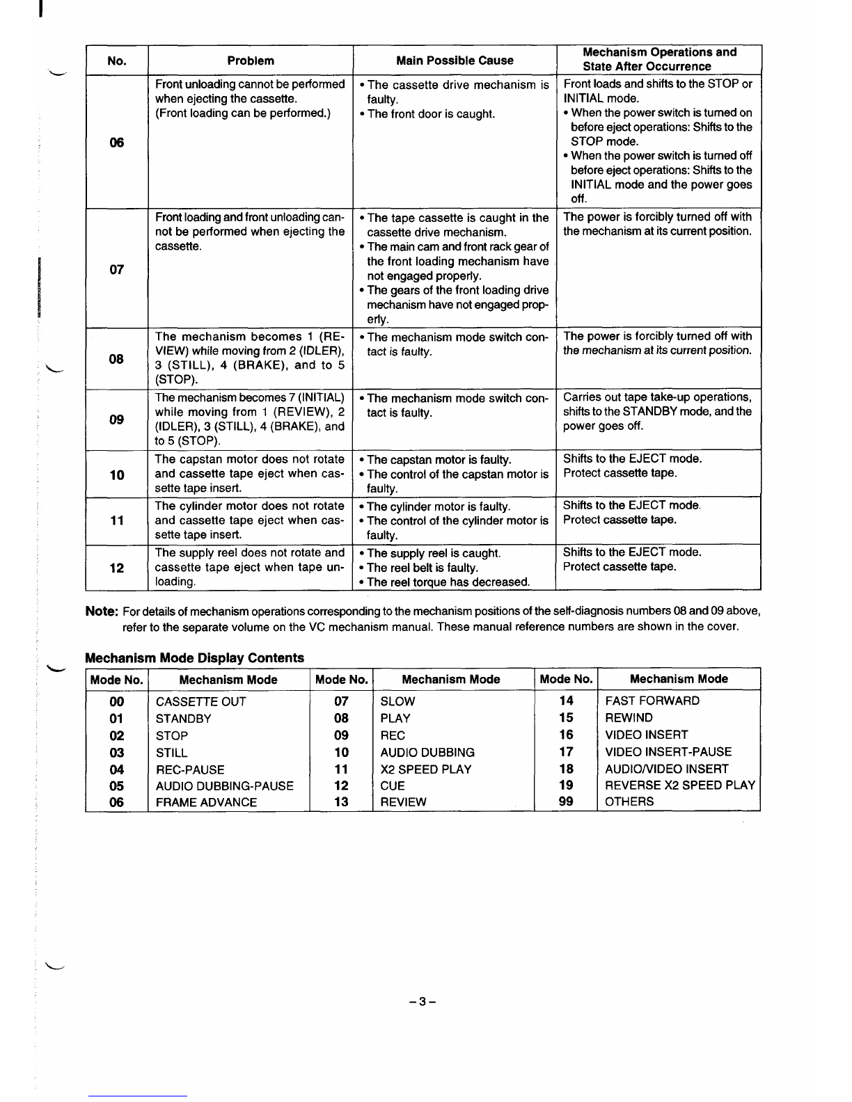
No. Problem Main Possible Cause Mechanism Operations and
State After Occurrence
Front unloading cannot be performed ●The cassette drive mechanism is Front loads and shifts to the STOP or
when ejecting the cassette. faulty. INITIAL mode.
(Front loading can be performed.) ●The front door is caught. ●When the power switch is turned on
before eject operations: Shifts to the
06 STOP mode.
●When the power switch is turned off
before eject operations: Shifts to the
INITIAL mode and the power goes
off .
Front loading and front unloading can- .The tape cassette is caught in the The power is forcibly turned off with
not be performed when ejecting the cassette drive mechanism. the mechanism at its current position.
cassette. ●The main cam and front rack gear of
07 the front loading mechanism have
not engaged properly.
●The gears of the front loading drive
mechanism have not engaged prop-
erly.
The mechanism becomes 1(RE- ●The mechanism mode switch con- The power is forcibly turned off with
08 VIEW) while moving from 2(IDLER), tact is faulty. the mechanism at its current position.
3(STILL), 4(BRAKE), and to 5
(STOP).
The mechanism becomes 7(INITIAL) ●The mechanism mode switch con- Carries out tape take-up operations,
09 while moving from 1(REVIEW), 2tact is faulty. shifts to the STANDBY mode, and the
(IDLER), 3(STILL), 4(BRAKE), and power goes off.
to 5(STOP).
The capstan motor does not rotate ●The capstan motor is faulty.
10
Shifts to the EJECT mode.
and cassette tape eject when cas- ●The control of the capstan motor is Protect cassette tape.
sette tape insert. faulty.
The cylinder motor does not rotate ●The cylinder motor is faulty.
11 Shifts to the EJECT mode,
and cassette tape eject when cas- ●The control of the cylinder motor is Protect cassette tape.
sette tape insert. faulty.
The supply reel does not rotate and ●The SUpply reel is caught. Shifts to the EJECT mode.
12 cassette tape eject when tape un- .The reel belt is faulty. Protect cassette tape.
loading. ●The reel torque has decreased.
Note: For details of mechanism operations corresponding to the mechanism positions of the self-diagnosis numbers 08 and 09 above,
refer to the separate volume on the VC mechanism manual. These manual reference numbers are shown in the cover.
Mechanism Mode Display Contents
Mode No. Mechanism Mode Mode No. Mechanism Mode Mode No. Mechanism Mode
00 CASSETTE OUT 07 SLOW 14 FAST FORWARD
01 STANDBY 08 PLAY 15 REWIND
02 STOP 09 REC 16 VIDEO INSERT
03 STILL 10 AUDIO DUBBING 17 VIDEO INSERT-PAUSE
04 REC-PAUSE 11 X2 SPEED PLAY 18 AUDIONIDEO INSERT
05 AUDIO DUBBING-PAUSE 12 CUE 19 REVERSE X2 SPEED PLAY
06 FRAME ADVANCE 13 REVIEW 99 OTHERS
-3–