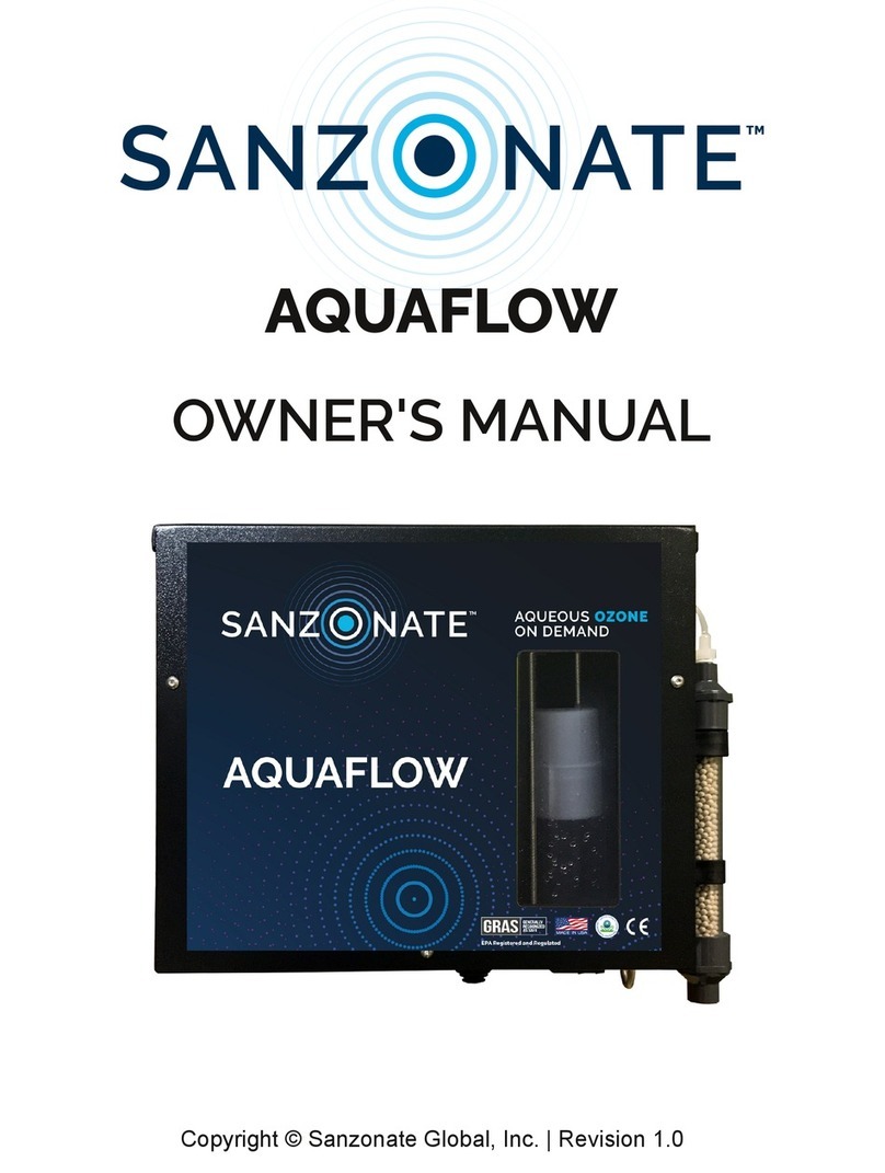
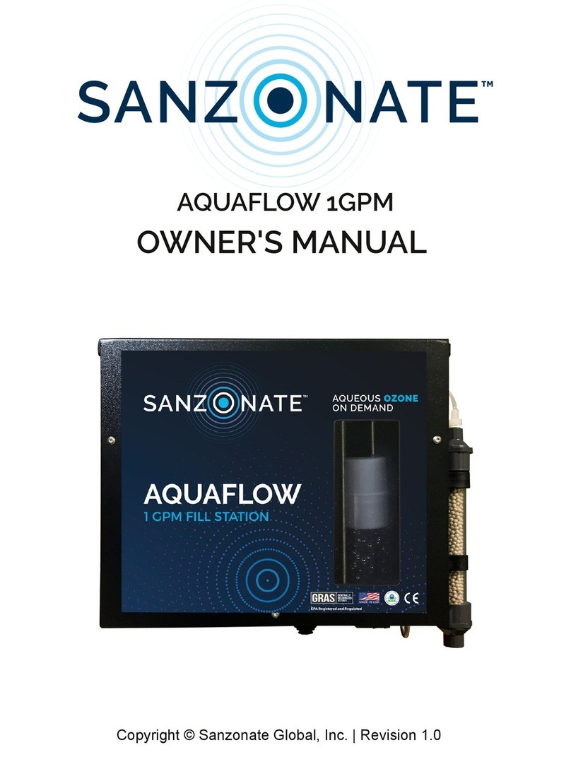
SANZONATE AQUAFLOW MAXI User manual

OWNER'S MANUAL
Rev. 1.0
AQUAFLOW MAXI

INTRODUCTION. . . . . . . . . . . . . . . . . . . . . . . . . . . . . . . . . . . . . . . . . . . . . . . . 3
SAFETY WARNINGS. . . . . . . . . . . . . . . . . . . . . . . . . . . . . . . . . . . . . . . . . . . . . 4
STATEMENT OF WARRANTY. . . . . . . . . . . . . . . . . . . . . . . . . . . . . . . . . . . . . 5
PRODUCT OVERVIEW. . . . . . . . . . . . . . . . . . . . . . . . . . . . . . . . . . . . . . . 6
INSTALLATION. . . . . . . . . . . . . . . . . . . . . . . . . . . . . . . . . . . . . . . . . . 7 - 11
POWER. . . . . . . . . . . . . . . . . . . . . . . . . . . . . . . . . . . . . . . . . . . . . . . 12 - 13
OPERATING USAGE TIPS. . . . . . . . . . . . . . . . . . . . . . . . . . . . . . . . . . . . . . 14
CHANGING THE AIR DRIER. . . . . . . . . . . . . . . . . . . . . . . . . . . . . . . 14 - 15
CLEANING THE INLET FILTER. . . . . . . . . . . . . . . . . . . . . . . . . . . . . . 16 - 17
HOUR METER. . . . . . . . . . . . . . . . . . . . . . . . . . . . . . . . . . . . . . . . . . . . 18
SAFETY DATA SHEET (SDS). . . . . . . . . . . . . . . . . . . . . . . . . . . . . . . . 19 - 24
Dimensions.............................................................38 x 16.5 x 40.6 cm (WxDxH)
Weight......................................................................................................................7.21kg
Max. Input Water Pressure..........................................................................5.8bars
Min. Input Water Pressure............................................................................2.7bars
Output Flow Rate........................................................................................11.36 lpm
ORP................................................................................................850mV [+/- 100mV]
PRODUCT SPECIFICATIONS
TABLE OF CONTENTS

3
Congratulations on the purchase of your new AQUAFLOW MAXI!
Your machine was constructed with the highest level of precision and care. All
new machines are rigorously inspected, tested and checked against our quality
control checklist.
This manual will guide you through the installation of the equipment and
provides answers to some common questions. Please read through this manual,
paying careful attention to the Safety Warnings section. Keep in mind that any
unnecessary damage, neglect or abuse of this machine will void your warranty.
Should you have any questions regarding maintenance, replacing parts or
ordering parts, please contact your authorized distributor.
If warranty questions should arise, contact your distributor for help.
The contents of this manual are based on the latest product information available at the time of publication. Sanzonate Global Inc. reserves the
right to make changes in price, color, materials, equipment, specifications or models at any time without notice.
INTRODUCTION
Our mission is to eliminate harmful chemical consumption
worldwide by developing innovative products that create
an environmentally safe and renewable cleaning
alternative.
Our AQUAFLOW MAXI is an example of this; bringing a new
dimension to traditional cleaning and purification.
This electronic device produces an aqueous ozone solution at concentrations
ranging from 0.8 - 1.5 ppm, on a cold city water supply. This is suitable for filling
floor cleaning equipment, mop buckets and other applications requiring a higher
flow rate.
Sanzonate Global Inc., uses corona discharge ozone generators. Their output is
calibrated at 700mg/hr @ 2.8 SCFH. This is higher than typical for ozone
generators of this size!

4
Always provide a copy of this manual to anyone using this
equipment. There is a proper way to use this machine; training,
although minimal, is recommended. Read this manual before
operating this machine to prevent the possibility of personal injury
to the operator or unintentional damage to the equipment.
• This machine produces an aqueous ozone solution and is intended for cleaning
only, and the solution it generates may be used in place of most
general-purpose cleaners.
• DO NOT put fingers or objects near the fan guard when the device is "ON."
• DO NOT disassemble this device. High voltage electricity exists inside this
device while it is "ON." and failure to follow this precaution could result in
electrical shock
• Power this device with the provided wall adapter only. It uses specific ratings for
correct operation. The power requirement for this device can be summarized to
12v DC @ 10A. The power cord connects to the device with a 2.1mm plug.
• NEVER restrict OR block the flow of solution while the unit is "ON.". This machine
was designed to operate with an open flow. Restricting or blocking its flow will
cause water to back up into the ozone destruct chamber. Should this happen, it
will need to be replaced for the machine to function properly.
• If you notice black droplets or stains underneath the machine REPLACE THE
DESTRUCT TUBE and contact your distributor. *Ozone gas cannot be destroyed
if the destruct media gets wet.
• DO NOT LEAVE THE MACHINE RUNNING OVER-NIGHT. This can cause
permanent damage to the ozone generators. A typical operating period should
not last longer than one hour at a time, followed by at least 20 minutes of cool
down time. Please contact your distributor with questions.
Consult this manual for troubleshooting help before reaching
out to your sales representative or distributor. The
"Troubleshooting" section addresses the most common
issues. (Pg.19)
SAFETY WARNINGS

5
Sanzonate Global Inc. makes every effort to assure our products meet high quality and
durability standards, and warrants to the original purchaser this product free from
defects in materials and workmanship for the period of 365 days beginning on the date
of purchase or order. Sanzonate Global Inc. in no event will be liable for injuries to
persons or property, or for incidental and contingent, special or consequential damages
arising from the use of our product. Neither Sanzonate Global Inc. nor any affiliate of
Sanzonate Global Inc. shall be responsible to customer or others for lost revenues, lost
profits, or other special, incidental, direct, indirect, or consequential damages or for loss
or damage or other expenses directly or indirectly arising from customer(s), or any other
person(s) use or inability to use Sanzonate Global Inc. product or for commercial loss of
any kind. No recovery against Sanzonate Global Inc.. Whether in contract, tort
(including negligence), strict liability or otherwise, shall be greater than the amount paid
by the customer for any Sanzonate Global Inc. product.
Some states do not allow the exclusion or limitation of incidental or consequential damages, so the above
limitation or exclusion may not apply to you.
STATEMENT OF WARRANTY

6
Take a moment to familiarize yourself with the unit. (Fig.1)
Note the orientation of the inlet and outlet ports. (Fig.2)
PRODUCT OVERVIEW
ON/OFF
SWITCH
FANEXHAUST
HOURMETER
POWERIN
(12VDCONLY)
FANFILTER
O3SOLUTION(OUT)
(AQUEOUSOZONE)
INLETPORT
(FRESHWATERSUPPLY)
O3DESTRUCT
(OUT)(ScrubbedAir)
(Fig.2)
(Fig.1)
PSIGauge
Min.45Max.85
AIRDRIER
(AIRIN)

7
INSTALLATION
YOU WILL NEED:
Included: Screws | Plastic Anchors | Mounting Template | Liquid Level
Not Included:
- Tape
- Pencil/Pen
(For Drywall) (For Concrete)
- 5/16" (8mm) Drill Bit - 5/16" (8mm) Masonry Bit
- Phillips screwdriver/drill - Hammer Drill
- Hammer or Mallet
- Phillips screwdriver/drill
Step 1: Determine the best suitable location for mounting your unit.
- Mount the unit a minimum of 4ft. above the floor
- And (preferably) within 4ft. (1.2m) of the electrical outlet intended to power the
unit.
Step 2: Place a piece of tape on each top corner of the mounting
template and secure the template against the wall. (Fig.3)
This machine is intended for commercial use only.
Installations may not be identical to this manual.
If you need help or have questions contact your distributor.
*The tape can be rolled into a
loop to make it double-sided.
Stick it to the back of the level,
then stick the level to the top-
center of the template. (Fig.3)
(Fig.3)

8
Step 3: Drill the holes for the anchors.
Drywall:
- Use a 5/16" (8mm) drill bit on the three (3) marks.
- Remove the template from the wall.
- Lightly tap the anchors into each hole until they are flush against the wall.
- Start the screws [#10-32 x 1-1/4] by hand until you can switch to a
screwdriver/
drill to finish tightening. Stop when head is 1/4" (6.3mm) away from the wall.
(Fig. 4)
Step 4: Hang the machine over the screw heads while aligning with the keyholes
on the back of the machine.
- It should hang tight against the wall.
- If necessary, remove the unit and slightly tighten the screws,
re-fitting until it's snug.
INSTALLATION (con't)
Concrete:
- Use a 5/16" (8mm) masonary drill with a hammer drill and drill holes on
the three (3) marks.
- Remove the template from the wall.
- Lightly tap the plastic anchors into each hole until they are flush against
the wall.
- Start the screws [#10-32 x 1-1/4] by hand until you can switch to a
screwdriver/drill to finish tightening. Stop when the screw head is
1/4" (6.3mm) off the wall (Fig.4).
(Fig.4)

9
INSTALLATION (con't)
Step 5: Connect the water filter (Fig. 5) to the INLET port located in the middle of
the unit. (Fig. 6) & (Fig.7)
Arrows located on the side of the filter point in the direction of water flow. When
installed the arrows should point UP (↑).
(Fig.7)
(Fig.6)
(Fig.5)

10
INSTALLATION (con't)
(Fig.10)
Step 6: Connect the 6ft black tubing into the bottom of the filter. (Fig. 8)
Step 7: Connect the white adapter to the cold water supply. (provided) (Fig.9)
A 3/4" garden faucet is a common connection point. (Fig.10)
The remaining end of black tubing connects this tube port.
Slowly, turn ON the water supply.
If you have a different style faucet or need assistance, contact your
distributor.
(Fig.9)
(Fig.8)
The inlet adapters come with only 1 black washer. You might find
that you need to install a second. Please contact your
distributor for assistance.

11
INSTALLATION (con't)
(Fig.12)
Step 8: Connect the blue hose to the black hose barb fitting on the bottom-
right of the MAXI.
Slide the hose onto the barb with a slight twisting motion. (Fig.11)
There is very little pressure in the blue solution hose; a clamp is not
needed. (Fig.12)
(Fig.11)

12
POWER
The AQUAFLOW MAXI uses an AC/DC Adapter (Power Supply) to convert mains
voltages into 12VDC.
Step 9: Connect the 3-prong male end into a wall outlet, preferrably a GFCI.
(Fig.13)
(Fig.13)
(Fig.14)
Step 10: Connect the female end into the AC/DC adapter. (Fig.14)

13
POWER (con't)
Step 11: Verify the blue LED on the 12V adapter is illuminated. (Fig.15)
Step 12: Connect the barrel jack from the power adapter into the power port
located on the lower-left side of the unit. (Fig.16)
NOTE: If the blue LED does not illuminate, contact your sales representative
for assistance.
(Fig.16)
(Fig.15)

14
OPERATING USAGE TIPS
Great job! You are finished with the installation and may begin using your NEW
AQUAFLOW MAXI!
To Use: Press-in the ON/OFF button located on the left side of the unit.
(Fig.17)
A BLUE light will illuminate inside the viewing window.
TheAirDrier:TheAQUAFLOWMAXIusesthemostadvanceddryingmediatofilter
theairbeforeenteringtheozonegenerators.
Thismediaishydroabsorbent,soakingupmicroscopicparticlesofwaterfromthe
incomingairwhilefilteringoutdust.
(Fig.17)
CHANGING THE AIR DRIER
1.Disconnectthetubingfromtheairdrier.(Fig.18A)
2.Holdthetopoftheairdrier,whilepullingawayfromtheMAXIunit.
(Fig.19)&(Fig.20)
3.Discardtheoldairdrier.
4.Removethenewairdrierfrompackaging.
5.Peelthe"REMOVE"stickerfromthebottomofthedrierandpulloffthegreencap.
6.PlaceonehandontheoppositesideoftheMAXItohelpcounterpushthenewairdrier
intotheclips.
7.Insertthenewdrieratanangletoensurethebottomclipisthefirsttogetsecured.(Fig.21)
8.Pushfirmlyuntilthesecond,topclipissecured.Slidethedrierdownuntilittouchesthetop
clip.
9.Reconnectthetubingtothehosebarbontopofthenewairdrier.

15
CHANGING THE AIR DRIER (con't)
Topreventdamagetothe3GPM,neverreplacetheairdrierwhiletheunitis"ON".
Extratubinghasbeenincludedinsidethemachine,donotbeafraidtouseit.You
maygentlypulloutsometubingtoassistwiththereplacement.Trynottopullmore
than2.0"total.Besuretogentlypushthetubingbackintothemachinewhen
finished.
Thereshouldbeanicesmoothbendinthetubingwithoutanykinksorfolds.(Fig.18B)
Thecapontopoftheairdriershouldberestingonthetopofthetopholdingclip.
(Fig.18C)
(Fig.19)
(Fig.18)
(Fig.21)
(Fig.20)
(C)
(B)
(A)

16
CLEANING THE INLET FILTER
A 100 mesh (150 microns) inlet water filter is used to prevent foreign objects from
obstructing the flow of solution inside your MAXI. Keeping the filter screen clean
will help prevent unnecessary maintenance issues and prolong the life of your
equipment.
We recommend after the first week from installation the screen inside the inlet
water filter should be inspected. Early inspections allow you to assess the quality
of the source water which will help determine the best maintenance schedule:
- If the filter is clean, continue inspections every 3-months.
- If the filter needs to be cleaned, you will want to perform inspections more
frequently (weekly) and might want to consider a larger pre-filter to be installed
ahead of the MAXI.
To Clean:
- Locate the water source and temporarily turn it, "OFF".
- Release pressure by briefly, turning powering "ON", to "OFF".
- Place a cup under the filter cap; there will be some water.
- Unscrew the filter cap from the main body. (Turn Left)(Fig.22)
- Pull the blue screen out to inspect it for rocks or mud. (Fig.23)
- If dirty, rinse the screen under a faucet with running water.
Reassembly:
- Align the raised ring on the inside-bottom of the filter cap
with the opening on the bottom of the blue filter screen.
- Re-install the screen and cap. (Turning Right).
DO NOT USE TOOLS to tighten the cap. Hand tighten only.
- Slowly turn ON the supply water valve.
- Check for leaks.
- Done.

17
(Fig.23)
(Fig.22)
CLEANING THE INLET FILTER (CON'T)

18
HOUR METER
The hour meter is Non-Resettable.
A digital hourglass will flash on the screen while in operation.
Display Resolution: While the total running hours is in range
0.0 - 9999.9H the resolution is 0.1H ≈ 6m
After the total running hours pass 10000H
the resolution changes to 1H ≈ 60m.
Change Filter Notification: "CLEAN AIR FILTER", "NOW"
The hour meter has been programmed to display an alert message indicating
that it is time to replace the air drier. The setpoint for the alarm starts at 400H
and counts down.
MaininterfaceDisplaysthetotalworkinghours.
Pressingthebuttononcedisplayscountdownalarmtotal
AlarmScreen
Flashes
Alternatively
Flashes
Alternatively
When the countdown reaches 0H, "CLEAN AIR FILTER" & "NOW" will flash back and forth. Press and
hold the button on the front of the hour meter for 5s to clear the reminder alarm and reset the timer to
400H.
Pressing and holding the button for 10s will reset the countdown alarm total to 400H.

1.1. Product identifier
Product name
: Sanzonate Global, Inc. Aqueous Ozone Solution
: n/a
Product code
1.2. Relevant identified uses of the substance or mixture and uses advised against
Use of the substance/mixture
:
For professional use only
Disinfectant/
Antimicrobial/Surface
Cleaning
Use advised against
:
None identified
1.3. Details of the supplier of the safety data sheet
SANZONATE GLOBAL INC.
12020 Shamrock Plaza Suite
200 Omaha, NE 68154
Tel: 1-855-424-6723
1.4. Emergency telephone number
Emergency number
: (1-855-424-6723 - 24 HOURS)
2.1. Classification of the substance or mixture
Classification
2.2. Label elements
Labelling
2.3. Other hazards
No additional information available
:
None known
2.4. Unknown acute toxicity
Not applicable
3.1. Substances
Not applicable
3.2. Mixture
This mixture does not contain any substances to be mentioned according to the criteria of section 2.2 of HazCom 2012. Dissolved ozone gas in water 0 to
2.0 ppm.
§The signal word, warning, is required under OSHA Hazards Communication Standard, 29 CFR 1910.1200, and is not meant to represent EPA pesticide labelling under FIFRA.
03/01/2023 EN (English)
Sanzonate Global, Inc. Aqueous Ozone Solution
Safety Data Sheet
according to the federal final rule of hazard communication revised on 2012 (HazCom 2012)
Date of issue: 06/01/2022 Revision date: 03/01/2023 Printed:03/01/2023 Version: 4.0
SECTION 1: Identification of the substance/mixture and of the company/undertaking
SECTION 3: Composition/information on ingredients
Not Classified
No labelling applicable
SECTION 2: Hazards identification

Sanzonate Global, Inc. Aqueous Ozone Solution
Safety Data Sheet
according to the federal final rule of hazard communication revised on 2012 (HazCom 2012)
03/01/2023
EN (English)
4.1. Description of first aid measures
First-aid measures after inhalation
:
Inhalation of aqueous ozone may lead to irritation of the lungs. If breathing is difficult, remove
victim to fresh air and keep at rest in a position comfortable for breathing. If exposure symptoms
persist, seek medical advice.
First-aid measures after skin contact
:
Not known to cause irritation, but if skin irritation occurs, wash well with fresh water. If skin
irritation persists, seek medical attention.
First-aid measures after eye contact
:
If eye irritation occurs with exposure to aqueous ozone, it is suggested to efficiently rinse eye
with potable water for 5 minutes. Remove contact lenses, if present and easy to do. Continue
rinsing. If eye irritation persists: Get medical advice and attention.
First-aid measures after ingestion
:
No specific measures have to be taken if the product is swallowed.
4.2. Most important symptoms and effects, both acute and delayed
Not known to be harmful to health in normal use.
4.3. Indication of any immediate medical attention and special treatment needed
Treat symptomatically.
5.1. Extinguishing media
Suitable extinguishing media
:
Use fire-extinguishing media appropriate for surrounding fire.
Unsuitable extinguishing media
:
None to our knowledge.
5.2. Special hazards arising from the substance or mixture
None known.
5.3. Advice for firefighters
Firefighting instructions
:
No special requirements.
Protective equipment for firefighters
:
No additional risk management measures required.
Other information
:
NA
6.1. Personal precautions, protective equipment and emergency procedures
General measures
:
Spilled material may present a slipping hazard.
6.2. Environmental precautions
None known.
6.3. Methods and material for containment and cleaning up
Methods for cleaning up
:
Allow the residual product to evaporate. No special procedures required.
6.4. Reference to other sections
For further information refer to section 8: Exposure-controls/personal protection. For disposal of residues refer to section 13: Disposal considerations.
SECTION 6: Accidental release measures
SECTION 4: First aid measures
SECTION 5: Firefighting measures
Table of contents
Other SANZONATE Water System manuals
Popular Water System manuals by other brands

Julabo
Julabo CORIO CD operating instructions

Grundfos
Grundfos UPS3 15-50/65 instructions

Riello
Riello Dialog Plus 300 instruction manual

Grunbeck
Grunbeck GENO-mat FE-Z Series Operation manual

Sears
Sears 390.250095 owner's manual

Cetetherm
Cetetherm Midi Compact SR144 Installation, service and operating instruction

Grundfos
Grundfos UPSe instructions

GSO
GSO RC-1L operating instructions

WaterLogic
WaterLogic 12-WL200CT manual

AVK
AVK 29 Series Installation, operation & maintenance manual

Greenway Home Products
Greenway Home Products Pro Series Installation instructions & owner's manual

aero-stream
aero-stream AS500-3 Operator's guide