Saracen TMV2 Product manual

Installation and Maintenance Guide
TMV2 Thermostatic Shower
Control
A TMV2 approved thermostatic shower; with a concentric control
mechanism, ideal for leisure applications.

Specification
Maximum static pressure: 10 Bar
Working pressure: 0.5-5Bar
Hot supply temperature: 55-65°C
Maximum hot supply temperature: 80°C
Cold supply temperature: Equal to or less than 25°C
Permitted supply pressure variation: 3:1
Factory Set Temperature: 38°C +/-2°C
Minimum temperature differential: 10°C
(between hot supply and the mixed outlet temperature)
Connection Size: 15mm
Standard: BSEN 1111 - HP-S
Approvals: WRAS, TMV2
Please Note: If the water supply is fed by gravity then the supply pressure
should be verified to ensure conditions of use are appropriate for the valve.
The valve must be installed in accordance with current regulations, specific to
the application and valve and in accordance with water supply (water fitting)
regulations 1999. Valves operating outside of these conditions cannot be
guaranteed to operate as a type 2 valve.
General Guidance
This installation guide is provided to give instruction on the installation practices
that should be observed to ensure the correct functioning of the Saracen TMV2
shower control. Failure to comply with these instructions will result in the warranty
becoming null and void.
In all cases before installing the shower it is imperative to ensure that the system
conditions i.e. pressures, temperatures and flow rates are within the limits stated
in the specification section.
The valve is suitable for installation on a solid wall, a stud partition, dry lined wall
or for fixing to a cubicle or panel.
Prior to installation please ensure that the pipework is flushed out and is free from
any system debris, i.e. sealant, PTFE tape, flux, solder or any other material that
could become trapped in the strainers or check valves. Failure to do this may
result in very poor flow performance and/or damage to the shower.
As thermostatic controls contain temperature sensitive components soldering on
or near the shower must be avoided.
1

2
Installation
Please Note: Easily accessible suitable service valves, must be fitted as close
as practical, on the hot and cold water supplies to the shower as an independent
means of isolating the water supplies should maintenance or servicing be
necessary.
This valve is factory pre-set so that the control handles are positioned in the
correct location. Do not turn the shafts until you have fitted the handles after
completing installation.
Ensure the hot and cold inlets are correctly connected as stated on the valve.
The Saracen TMV2 Thermostatic Control
Valve is pre-assembled so a shower hose
can be fitted, to the bottom connection.
This means that when the valve is fitted
with the hot water coming in from the left
hand side, indicated by the red spot, the
water outlet is on the bottom of the valve
and has a ½” BSP threaded male outlet.
Alternatively if you intend to use the
shower valve with a rigid riser then you
can switch the blanking plug at the top
of the shower with the connection at the
bottom.
To do this, use an allen key (10mm) to
remove the ½” outlet connection at the
bottom of the shower.
On the opposite side, use a suitable
spanner to remove the blanking plug.
Hot Water
1/2″ Male
Hot Water
Outlet

Re-insert the connection in the top of the shower
and tighten with the allen key.
Repeat with the opposite side, using a spanner to
re-tighten the blanking plug in the bottom of the
shower.
Ensure in all instances the o-rings are
intact and the connection and blanking
plug are securely tighten to form a water
tight seal.
Prior to installation it is advisable to
unscrew the two 90° elbows and lubricate
the o-ring with a WRAS approved silicon
based grease, before re-inserting.
Exposed Shower Installation
The supply pipework can be plumbed from above or below but must be aligned
with the hot and cold connections which have 155mm centres.
Connect the 15mm supply pipework using standard the standard compression nut
and olives supplied on the shower valve
3
Hot Water
155mm approx
Hot Water
Plug

Complete the fitting of the pipework and the tiling leaving the pipework as shown.
Leave 155mm (+ or - 5mm) between centers and about 30mm out from the
finished surface.
Remove the backplate from the shower valve to do this use a allen key (2.5mm)
to remove the securing grub screws.
Position the plate centrally between the feed pipes and mark the screw positions,
check this fits by holding the valve in position. Drill plug and screw the back plate
to the wall.
Place the chrome cover discs over the
compression nuts on either elbow of the shower
valve and align the valve to the feed pipes and
onto the wall bracket.
Carefully tighten up the compression nuts to
hold the mixer valve in place.
Ensure the shower valve outlet is pointing
in the correct direction (with the hot feed on
the left side marked with a red indicator).
Replace the locking grub screws to hold the
mixer valve onto the wall plate.
Take the seperate control lever and screw
it into the connection on the top of the ‘on/
off’ ring, ready for the shower to be used,
4

Concealed Shower Installation
The shower control should be installed within the
wall or panelled system between 55-70mm behind
the finished wall surface.
The supply pipework can be plumbed from above
or below but must be aligned with the hot and cold
connections which have 155mm centres.
Connect the 15mm supply pipework using standard
the standard compression nut and olives supplied
on the shower valve
Complete the fitting of the pipework and the
tiling leaving the pipework as shown.
Remove the backplate from the shower valve
to do this use a allen key (2.5mm) to remove
the securing grub screws.
Position the plate centrally between the feed pipes and mark the screw positions,
check this fits by holding the valve in position. Drill plug and screw the back plate
in position.
Carefully tighten up the compression nuts to hold the
mixer valve in place.
Ensure the shower valve outlet is pointing in the
correct direction (with the hot feed on the left side
marked with a red indicator). Replace the locking
grub screws to hold the mixer valve onto the wall
plate.
A pipe must be fitted from the concealed shower
outlet to the location of the shower head (not
supplied).
55mm
Minimum
155mm approx.
5

Once the shower control and shower outlet has been fitted, check to ensure all
connections are watertight.
Fit the concealing plate by pushing it over
the control handle until it is flushed with the
finished wall surface.
Please note sufficient space should be left
behing the concealing place to allow for
maintenance to be carried out.
Take the seperate control lever and screw
it into the connection on the top of the
‘on/off’ ring, ready for the shower to be
used,
Operation
The Saracen Shower is a TMV2 approved concentric controls; meaning it
comprises of a ring in ring design.
To adjust the temperature you simply rotate the the inner (central) ring. The
shower is pre-set to 38°C, to reduce the
temperature rotate the lever clockwise or
to increase the temperature, press the
override button which will allow you to
pass the safety stop and continue to rotate
the lever anti-clockwise.
The flow control is adjusted by rotating the
outer ring clockwise to turn the shower on
and anti-clockwise to close it,
6
HC
OFF
ON

7
Commisioning
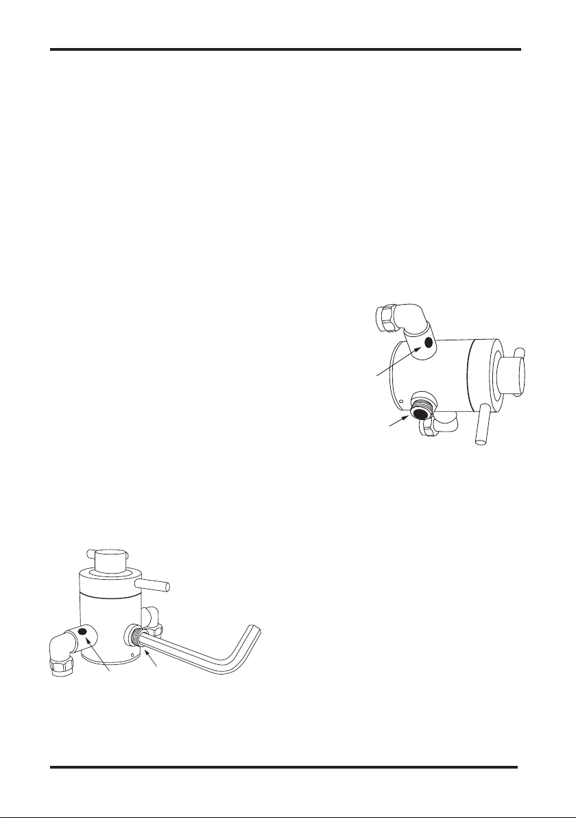
Ensure both isolation valves are fully open on the hot and cold water supplies.
With the temperature control handle in the pre-set ‘stop’ position, turn on the shower
and let it flow until the hot water temperature has stabilised. Check the temperature
is 38˚C +/-2˚C.
If your temperature is not 38˚C the following operation should only be carried out by
a competent person:
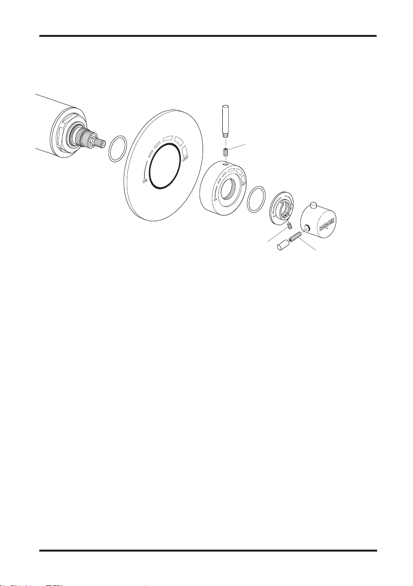
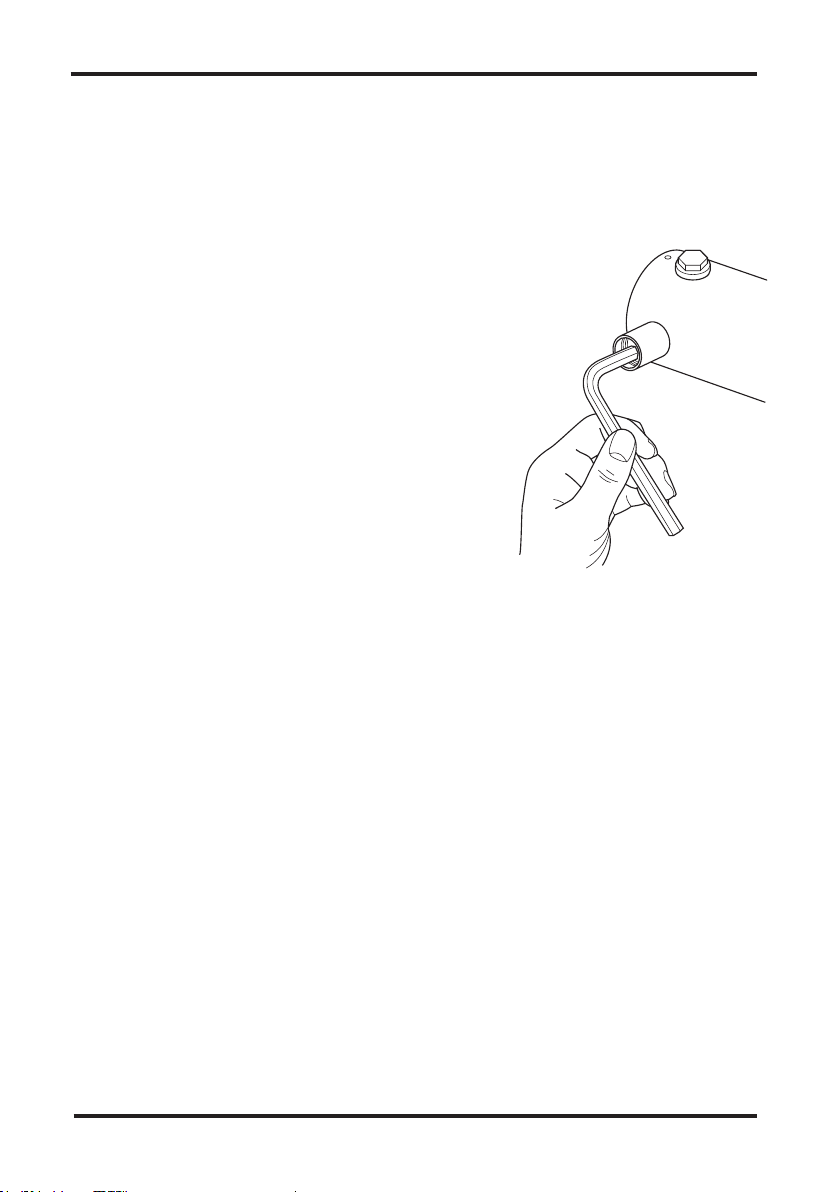
Position the temperature control knob at the stop. Unscrew the temperature lever to
expose the grub screw, use a 4mm allen key to remove the screw which allows the
temperature control handle to be removed.
Turn the spindle by hand (using grips may damage the slines on the control
and prevent the handle from gripping upon re-aeseembly) to adjust the pre-set
temperature to the required setting of 38°C, turning clockwise will decrease and
turning anti-clockwise will increase the termperature, test the water outlet using a
calibrated temperature probe, once set re-assemble the control handle.
Recommended Outlet Temperature & Performance Checks
Application Recommended Temperature
Shower 41°C
Please note:
• The mixed water temperature can be 2°C above the recommended maximum set
outlet temperatures.
• The mixed water temperature at the terminal fitting should never exceed 46°C. It
is not a safe bathing temperature for adults or children.
• The British Burns Association recommends 37 to 37.5°C as a comfortable bathing
temperature for children. In premises covered by the Care Standards Act 2000,
the maximum mixed water outlet temperature is 43°C.
Performance Checks
The performance of the Saracen Thermostatic Shower Control should be checked
on an annual basis and verified against the original installation performance. The
following check should be carried out:
• Check the mixed water temperature at the outlet using a callibrated temperature
probe
• Carry out the cold water supply isolation test by isolating the cold water supply to
the bar shower, wait for five seconds if water is still flowing check the temperature
is below 48°C
If there is residual flow, then this is acceptable providing the temperature of the
seeping water is no more than 2°C above the designated maximum water outlet
temperature setting of the valve.

8
Maintenance
Accessing the cartridge
Isolate the water supplies on both the hot and cold. Unscrew the temperature
lever to expose the grub screw, use a 3mm allen key to loosen the screw which
allows the temperature control handle to be removed.
You will now be able to see a further grub screw, use a 2.5mm allen key to loosen
this, unscrew the flow lever handle which will expose a further grub screw, use a
2.5mm allen key to again loosen this, which will allow the flow control handle to
be removed from the front of the shower.
Then use a spanner on the flats of the inner head of the shower which surrounds
the base of the exposed cartridge, to unscrew the headwork.
Once this is removed you can pull away the complete brass cartridge; if you have
difficulting doing this you can lift away the shroud from around the cartridge which
exposes some flats on the base of the cartrige, so even though the cartridge is
not screwed in, by using a spanner on these flats it will help ease the cartridge
out of situ.
Grub screw
Grub screw
Grub scre
w

9
Accessing the strainer and check valve
The strainer and check valve are situated on the connection between the main
shower body and the supply elbow for both the hot and cold. To access these
isolate the water supplies.
Loosen the compression connection which
will allow the elbow to be unscrewed from the
connection on the shower body. This will allow
access to the connection which housing the
two compoenents; insert an 10mm allen key to
remove this connection from the main body.
Once this section is removed you can use long
nosed pliers to remove the circlip and then
push both the strainer and the check valve free
from the housing.
Once removed you may either replace or rinse under clean running water and
re-fit.

10
Exploded Diagram
Flow Control handle
Lever
Grub screw
Bezel for concealed shower
Outlet blanking plug
(interchangeable with
outlet connector)
Outlet connector
(interchangeable with
blanking plug)
Strainer
Circlip
Seal
Seal
Body
Connection elbow
Connection tube
Check valve
Temperature
Control knob
Temperature
Index
Mounting plate
Mounting screws (3)
Thermostatic Cartridge
Grub screw Grub screw
Lever
Cartridge
shroud
Headwork
Bezel
Nut
Olive

Wolseley UK Head Office
The Wolseley Center, Harrison Way, Spa Park,
Royal Leamington Spa, CV31 3HH
For further information please call:
01765 690 690
or visit www.wolseley.co.uk
ZINS100200_002_03-17
Wolseley UK reserves the right to make changes to the product which may
effect the accuracy of the information contained in this guide.
Table of contents
Other Saracen Bathroom Fixture manuals
Popular Bathroom Fixture manuals by other brands

Clou
Clou Vale CL/03.03160 installation instructions

Helvex
Helvex PREMIER UH-3005-WOA installation guide

Villeroy & Boch
Villeroy & Boch Squaro Super Flat installation instructions

MAAX
MAAX 105539 installation instructions

Kalia
Kalia Kareo BF1998 installation instructions

Exclusive Heritage
Exclusive Heritage CO-10160D installation guide

Signature Hardware
Signature Hardware GUNTHER 953361 manual

Kohler
Kohler C3-230 quick start guide

Hans Grohe
Hans Grohe Crometta 1jet 26331400 Assembly instructions

SANPLAST
SANPLAST KN4 installation guide

Hans Grohe
Hans Grohe Rainfinity 130 3jet 26864700 Assembly instructions

Utopia
Utopia You installation guide