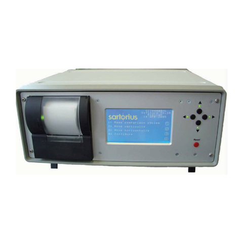
Sartorius PR 5610 User manual

Sartorius Hamburg GmbH, Meiendorfer Str. 205, 22145 Hamburg, Germany
Tel:+49.40.67960.303 Fax:+49.40.67960.383
System Weighing Controller
PR 5610
Installation Manual
Installation manual 9499 050 60004 Edition 4 27.07.2004 A4 FZ
for PR 5610 Release: 3.12

Please note
Any information in this document is subject to change without notice and does not represent a commitment on the part of
SARTORIUS. This product should be operated only by trained and qualified personnel. In correspondence concerning this product the
type, name and release number as well as all license numbers in relation to the product have to be quoted.
Important
This product is partly copyrighted. It may not be modified or copied and may not be used without purchasing or written authority
from the copyright owner (SARTORIUS). By using this product, you agree to be bound by the terms stated herein.
Bitte beachten
Alle Angaben in diesem Dokument sind unverbindlich für SARTORIUS und stehen unter Änderungsvorbehalt. Die Bedienung des
Produktes darf nur von geschultem, fach- und sachkundigem Personal durchgeführt werden. Bei Schriftwechsel über dieses Produkt
bitte Typ, Bezeichnung und Versionsnummer sowie alle mit dem Produkt in Zusammenhang stehenden Lizenznummern angeben.
Wichtig
Dieses Produkt ist in Teilen urheberrechtlich geschützt. Es darf nicht verändert oder kopiert und ohne Erwerb oder schriftliche
Einwilligung des unheberrechtlichen Eigentümers (SARTORIUS) nicht benutzt werden. Durch die Benutzung dieses Produktes werden
obige Bestimmungen von Ihnen anerkannt.
Veuillez noter, s.v.p.
L'exploitation de ce produit ne doit s'effectuer que par du personnel autorisé. Dans votre correspondance se rapportant au présent
produit, veuillez toujours spécifier le numéro de type, la description et le numéro de version ainsi que tous les numéros de licence en
rapport avec ce produit.
Important
Les droits d'auteur de toutes les parties de ce produit sont réservés. Ce produit ne doit être ni utilisé ni changé ni copié sans achat
de la licence ou accord par écrit. L'utilisation du produit implique la reconnaissance des conditions mentionnées ci-avant.

PR 5610 Installation Manual List of Contents
Sartorius 1
Contents
1SAFETY HINTS, ELECTRICAL PROTECTION CLASS ................................................................................ 5
1.1 APPLICATION OF THE INSTRUMENT......................................................................................................................... 5
1.2 INITIAL INSPECTION................................................................................................................................................ 5
1.3 BEFORE COMMISSIONING........................................................................................................................................ 5
1.3.1 Installation.................................................................................................................................................... 5
1.3.2 Electrostatically sensitive components......................................................................................................... 6
1.3.3 Protective earth ............................................................................................................................................ 6
1.3.4 Failure and excessive stress ......................................................................................................................... 7
1.3.5 For special attention..................................................................................................................................... 7
1.3.6 Fuse .............................................................................................................................................................. 7
1.4 REPAIR AND MAINTENANCE.................................................................................................................................... 8
1.4.1 Soldering work.............................................................................................................................................. 8
1.5 DISPOSAL ............................................................................................................................................................... 9
1.6 CLEANING .............................................................................................................................................................. 9
2SYSTEM WEIGHING CONTROLLER............................................................................................................. 10
2.1 BASIC INSTRUMENT SURVEY ................................................................................................................................10
2.2 OPTIONS............................................................................................................................................................... 11
2.2.1 Program extensions (optional) ................................................................................................................... 12
2.2.2 Plug-in cards and modules (optional)........................................................................................................ 13
2.3 HOUSING.............................................................................................................................................................. 14
2.4 DESCRIPTION OF CONTROLS ................................................................................................................................. 15
2.4.1 Display........................................................................................................................................................ 15
2.4.2 Keypad........................................................................................................................................................ 16
2.4.3 Operating concept ...................................................................................................................................... 17
3INSTALLING THE INSTRUMENT AND OPTIONS ...................................................................................... 19
3.1 MECHANICAL PREPARATION................................................................................................................................. 19
3.2 HARDWARE CONSTRUCTION................................................................................................................................. 19
3.2.1 Installing the options .................................................................................................................................. 20
3.2.2 Digital Board (Board 2) ............................................................................................................................. 20
3.2.3 Cable gland and connection....................................................................................................................... 21
3.3 MAINBOARD (BOARD 1)....................................................................................................................................... 21
3.3.1 Load cell cable / cable junction box........................................................................................................... 22
3.3.2 External PC keyboard................................................................................................................................. 24
3.3.3 Bar code reader.......................................................................................................................................... 25
3.3.4 RS 232 Built-in interface ............................................................................................................................ 26
3.4 OPTIONS............................................................................................................................................................... 29
3.4.1 PR 1713/04 Serial I/O ................................................................................................................................ 29
3.4.2 PR 1713/05 RAM extension........................................................................................................................ 35
3.4.3 PR 1713/06 Analog output card................................................................................................................. 36
3.4.4 PR 1713/07 Analog I/O .............................................................................................................................. 38
3.4.5 PR 1713/08 BCD output............................................................................................................................. 40
3.4.6 PR 1713/12 4 Opto inputs / 4 Opto outputs................................................................................................ 43
3.4.7 PR 1713/13 DIOS master ........................................................................................................................... 45
3.4.8 PR 1713/14 Ethernet................................................................................................................................... 48
3.4.9 PR 1713/15 4 Opto inputs / 4 Relay outputs.............................................................................................. 50
3.4.10 PR 1713/17 6 Opto inputs / 8 Opto outputs................................................................................................ 52
3.4.11 PR 1721/11 Profibus interface .................................................................................................................. 54
3.4.12 PR 1721/12 Interbus interface................................................................................................................... 55
3.4.13 PR 1721/14 DeviceNet interface................................................................................................................ 56
4COMMISSIONING............................................................................................................................................... 57
4.1 DATA SAVING / POWER FAILURE........................................................................................................................... 57
4.1.1 Calibration data.......................................................................................................................................... 57
4.1.2 Configuration data...................................................................................................................................... 58
4.1.3 Programming with PR 1750....................................................................................................................... 58

List of Contents PR 5610 Installation Manual
2 Sartorius
4.1.4 Cold / Warm start ....................................................................................................................................... 58
4.2 DISPLAY ELEMENTS AND CONTROLS..................................................................................................................... 59
4.2.1 Control signals............................................................................................................................................ 59
4.2.2 Language .................................................................................................................................................... 59
4.2.3 Operating concept ‘Commissioning’.......................................................................................................... 60
4.3 MAIN MENU.......................................................................................................................................................... 61
4.3.1 Function setup ............................................................................................................................................ 61
4.3.2 Boot menu................................................................................................................................................... 65
4.4 WEIGHING POINT ASSIGNMENT............................................................................................................................. 69
4.4.1 Error messages on the weight display........................................................................................................ 70
4.4.2 W&M Parameter......................................................................................................................................... 71
4.5 CALIBRATION, INTERNAL ADC............................................................................................................................ 72
4.5.1 Calibration sequence.................................................................................................................................. 72
4.5.2 Error messages at calibration start............................................................................................................ 72
4.5.3 Calibration / Configuration counters......................................................................................................... 72
4.5.4 Select weighing point.................................................................................................................................. 73
4.5.5 Display calibration data............................................................................................................................. 73
4.5.6 Select calibration mode .............................................................................................................................. 73
4.5.7 Set full scale................................................................................................................................................ 74
4.5.8 Set step width.............................................................................................................................................. 74
4.5.9 Set dead load ..............................................................................................................................................74
4.5.10 Set full scale deflection (span).................................................................................................................... 75
4.5.11 Calculate test value..................................................................................................................................... 76
4.5.12 Exit calibration........................................................................................................................................... 77
4.5.13 Set parameters............................................................................................................................................ 78
4.6 CONFIGURATION FOR 'LIQUID', 'USER', 'GWT-SCALE', 'XBPI-SCALE'................................................................... 80
4.6.1 Weighing point function liquid counter...................................................................................................... 80
4.6.2 Weighing point function GWT-scale........................................................................................................... 81
4.6.3 Weighing point function User-scale ........................................................................................................... 81
4.6.4 Weighing point function xBPI-scale........................................................................................................... 82
4.7 XBPI SCALE......................................................................................................................................................... 83
4.7.1 xBPI Serial port setup................................................................................................................................. 84
4.7.2 xBPI Weighing point assignment and configuration.................................................................................. 84
4.7.3 xBPI Platform configuration ...................................................................................................................... 85
4.7.4 xBPI Scale parameters ............................................................................................................................... 86
4.7.5 xBPI Scale parameter tables....................................................................................................................... 87
4.7.6 xBPI Scale setting deadload....................................................................................................................... 89
4.7.7 xBPI Scale error message........................................................................................................................... 89
4.7.8 xBPI Calibration with internal weight........................................................................................................ 90
4.7.9 xBPI Calibration with user weight ............................................................................................................. 90
4.7.10 xBPI Calibration with automatic weight recognition................................................................................. 91
4.7.11 xBPI Calibration with preset weight........................................................................................................... 91
4.8 CONFIGURATION OF NON-WEIGHING POINT RELATED PARAMETERS ..................................................................... 92
4.8.1 Set clock (date and time)............................................................................................................................. 92
4.8.2 Serial ports ................................................................................................................................................. 92
4.8.3 Software parameters................................................................................................................................... 94
4.8.4 Fieldbus parameter..................................................................................................................................... 96
4.8.5 Licence setup .............................................................................................................................................. 97
4.8.6 Show board number.................................................................................................................................... 98
4.8.7 Print setup data........................................................................................................................................... 98
4.8.8 Last fault..................................................................................................................................................... 98
4.8.9 Refresh display............................................................................................................................................ 98
4.8.10 I/O Slots ...................................................................................................................................................... 99
4.8.11 Show Version.............................................................................................................................................. 99
4.8.12 Enable download...................................................................................................................................... 100
4.8.13 Reboot....................................................................................................................................................... 100
4.9 CONFIG PROGRAM FOR APPLICATION PARAMETERS............................................................................................ 100
4.10 MODBUS / J-BUS PROTOCOL.......................................................................................................................... 101
4.10.1 Communication......................................................................................................................................... 101
4.10.2 Function 1 or 2: Read n bits..................................................................................................................... 102
4.10.3 Function 3 or 4: Read n successive words ............................................................................................... 102
4.10.4 Function 5: Write a bit ............................................................................................................................. 103

PR 5610 Installation Manual List of Contents
Sartorius 3
4.10.5 Function 6: Write a word ......................................................................................................................... 103
4.10.6 Function 8: Diagnosis .............................................................................................................................. 104
4.10.7 Function 15: write n successive bits......................................................................................................... 104
4.10.8 Function 16: write n successive words..................................................................................................... 105
4.10.9 MODBUS / J-BUS error messages........................................................................................................... 105
4.10.10 MODBUS / J-BUS Addresses.................................................................................................................. 106
5COMMISSIONING WITH TERMINAL.......................................................................................................... 107
5.1 SYSTEM CONSOLE: CONNECTING MENU STRUCTURE........................................................................................... 107
5.1.1 Connecting PR 5610 to PC....................................................................................................................... 107
5.1.2 Terminal program..................................................................................................................................... 107
5.1.3 Main-Command-Level menu structure.................................................................................................... 108
5.1.4 General operating notes........................................................................................................................... 110
5.2 CONFIGURATION ................................................................................................................................................ 111
5.2.1 Set date ..................................................................................................................................................... 111
5.2.2 Set time ..................................................................................................................................................... 112
5.2.3 Serial port setup........................................................................................................................................ 112
5.2.4 Entry of software licence numbers............................................................................................................ 114
5.2.5 Entry of software parameters ................................................................................................................... 115
5.2.6 Fieldbus parameter................................................................................................................................... 116
5.2.7 Entry of user-defined units........................................................................................................................ 117
5.2.8 Printing all configuration data................................................................................................................. 117
5.3 WEIGHING POINT MASK...................................................................................................................................... 118
5.3.1 Weighing point assignment....................................................................................................................... 119
5.4 WEIGHING POINT PARAMETERS: STORING, SAVING, PROTECTING....................................................................... 119
5.4.1 Access protection: CAL-switch................................................................................................................. 119
5.4.2 Saving the weighing point parameters in EAROM................................................................................... 121
5.5 INTERNAL ADC, PARAMETERS........................................................................................................................... 122
5.5.1 Editing functions for parameter entry ...................................................................................................... 122
5.5.2 Filter: Analog Filter ................................................................................................................................. 123
5.5.3 Analog test mode: Testmode..................................................................................................................... 123
5.5.4 Measuring time: Meastime ....................................................................................................................... 123
5.5.5 Standstill detection.................................................................................................................................... 123
5.5.6 Zero set range: Zeroset.rn........................................................................................................................ 123
5.5.7 Automatic zero tracking............................................................................................................................ 124
5.5.8 Automatic zero correction switch-on/off................................................................................................... 124
5.5.9 Zero tracking range: Zerotrk.rn ............................................................................................................... 124
5.5.10 Zero tracking stepwidth: Zerotrk.st.......................................................................................................... 124
5.5.11 Zero tracking interval: Zerotrk.ti.............................................................................................................. 124
5.5.12 Multirange scale....................................................................................................................................... 124
5.5.13 Tare time-out: Tare timot ......................................................................................................................... 124
5.5.14 Maximum permissible overload: Overload .............................................................................................. 125
5.5.15 Min. weight limit for print-out: no p below .............................................................................................. 125
5.5.16 Stepwidth (scale divisions): Stepwidth...................................................................................................... 125
5.5.17 W&M mode: W &M.................................................................................................................................. 125
5.6 WEIGHING POINT CALIBRATION.......................................................................................................................... 126
5.6.1 Calibration data........................................................................................................................................ 126
5.6.2 Editing functions for parameter entry ...................................................................................................... 127
5.6.3 Adjusting the full scale value: Fullscale................................................................................................... 127
5.6.4 Default span.............................................................................................................................................. 128
5.6.5 Weighing point calibration procedure / sequence.................................................................................... 128
5.6.6 Weighing point calibration with weights.................................................................................................. 128
5.6.7 Weighing point calibration without weights............................................................................................. 131
5.6.8 Error messages in the calibration menu................................................................................................... 134
5.6.9 Liquid counter........................................................................................................................................... 135
5.6.10 Customer-specific weighing point (user).................................................................................................. 136
5.6.11 GWT Scale................................................................................................................................................ 138
5.6.12 Sartorius scale (xBPI)............................................................................................................................... 139
5.7 SUB-MENU SERVICE ........................................................................................................................................... 140
5.7.1 Available memory in PR 5610.................................................................................................................. 140
5.7.2 Show hardware configuration .................................................................................................................. 141
5.7.3 Testing the input and output modules....................................................................................................... 141

List of Contents PR 5610 Installation Manual
4 Sartorius
5.7.4 Printing all configuration data................................................................................................................. 145
5.8 IEC 61131 OPERATING LEVEL............................................................................................................................ 146
6TECHNICAL DATA........................................................................................................................................... 147
6.1 ANALOG PART, A/D CONVERSION...................................................................................................................... 147
6.1.1 Accuracy and stability .............................................................................................................................. 147
6.1.2 Sensitivity.................................................................................................................................................. 147
6.1.3 Load cells.................................................................................................................................................. 147
6.1.4 Safe condition ........................................................................................................................................... 147
6.1.5 EC-Declaration of Conformity ................................................................................................................. 148
6.1.6 Certificate of type approval PR 1713, PR 5610 (X5), PR 5710 (X6) ....................................................... 149
6.1.7 Location of seals PR 1713, PR 5610 (X5)................................................................................................ 150
6.1.8 Location of seals PR 5710 (X6), foil PR 5610 (X5).................................................................................. 151
6.2 DIGITAL PART..................................................................................................................................................... 152
6.2.1 Backup battery.......................................................................................................................................... 152
6.2.2 Display...................................................................................................................................................... 152
6.2.3 Keypad...................................................................................................................................................... 152
6.2.4 External keyboard..................................................................................................................................... 152
6.2.5 Builtin RS 232 interface............................................................................................................................ 152
6.2.6 Power supply ............................................................................................................................................ 152
6.3 ENVIRONMENTAL EFFECTS................................................................................................................................. 153
6.3.1 Power voltage sags................................................................................................................................... 153
6.3.2 Environmental conditions......................................................................................................................... 153
6.3.3 Electromagnetic immunity........................................................................................................................ 153
6.3.4 RF interference suppression..................................................................................................................... 153
6.4 MECHANICAL DATA............................................................................................................................................ 154
6.4.1 Construction type...................................................................................................................................... 154
6.4.2 Dimensions ............................................................................................................................................... 154
6.4.3 Connections .............................................................................................................................................. 154
6.4.4 Accessories ............................................................................................................................................... 154
6.4.5 Weight....................................................................................................................................................... 154
6.4.6 Installation kit (optional).......................................................................................................................... 154
6.5 FIELD BUS OPTIONS ............................................................................................................................................ 155
6.5.1 Interbus-S/ Profibus-DP/ DeviceNet ........................................................................................................ 155
6.5.2 GSD file for PR 1721 Profibus DP........................................................................................................... 156
6.5.3 EDS-file for PR 1721 DeviceNet .............................................................................................................. 157
7ANNEX ................................................................................................................................................................. 158
7.1 SPARE PARTS...................................................................................................................................................... 158
7.2 FURTHER DOCUMENTS........................................................................................................................................ 158
7.3 GLOSSARY.......................................................................................................................................................... 158
8INDEX .................................................................................................................................................................. 159

PR 5610 Installation Manual Safety Hints
Sartorius 5
1 SAFETY HINTS, ELECTRICAL PROTECTION CLASS
This instrument was built and tested in accordance with the safety regulations for
measuring and control instrumentation for protection class I (protective earth connection)
according to IEC 1010/ EN61010 or VDE 0411. The instrument was delivered in safe
condition. To maintain this condition and to ensure safe operation, the operator must
follow the hints and warnings given in this documentation.
1.1 Application of the instrument
The instrument is intended exclusively for application in weighing and batching installations and is particularly
suitable for tank and hopper weighing, weighbridges, platform scales, crane weighing, batching systems and as
a weight indicator in intelligent control systems. Product operation, commissioning and maintenance must be
done by well trained and qualified persons who know of the risks and avoid them, or take measures to protect
themselves.
The instrument is state of the art. No warranty is taken that the product is free of errors, especially with
reference to the software and hardware required for operation and supplied by third parties. The manufacturer
does not take any liability for damage caused by incorrect use of this product. Using this product implies
recognition of the above-mentioned regulations.
1.2 Initial inspection
Check the contents of the consignment for completeness and note whether any damage has occurred during
transport. If the content is incomplete or damaged, a claim must be filed with the carrier immediately and the
Sartorius sales or service organization must be informed to permit repair or replacement of the unit.
1.3 Before commissioning
Visual inspection !
Before commissioning, after storage and transport, the instrument must be inspected
visually to preclude mechanical damage.
1.3.1 Installation
The instrument has a mounting bracket with holes in different distances and can be mounted adjustable
between rubber disks by knurled-head screws to the detachable mounting bracket. The stainless steel housing
of the instrument fulfills IP 65. The unit can be mounted in any position, however, the PG glands should not
point upwards (water). Before commissioning the instrument, all unused instrument apertures must be closed
with blind plugs. For cooling the instrument, the air circulation must not be hampered. Heat influences, e.g.
direct sun radiation, must be avoided. The environmental conditions specified in the technical data must be
taken into account. The unit is suitable for:
Table-top mounting: The unit stands on the detachable mounting bracket.
Wall mounting: Mount mounting bracket on the wall. The unit is held by knurled-head screws.
Installation in
control cabinets:
With installation brackets, the optional installation kit PR 1713/91
has to be ordered.

Safety Hints PR 5610 Installation Manual
6Sartorius
1.3.2 Electrostatically sensitive components
This instrument contains electrostatically sensitive components. Therefore, potential equalization must be
provided when working at the open instrument (antistatic protection).
Opening the instrument
CAUTION
DANGER TO LIFE !
Working at the switched on unit may be dangerous to life. Disconnect the
instrument from the supply voltage! When removing covers or parts by means of
tools, live parts or terminals may be exposed. Capacitors in the unit may still be
charged also after disconnecting the unit from all voltage sources. Before
selecting a different supply voltage and before replacing the loadcell fuse, the
unit must be disconnected from all voltage sources.
1.3.2.1 Earthing
Earthing of the unit must be via the protective earth conductor PE.
1.3.3 Protective earth
The connecting cable of the unit must comply with the regulations in accordance with VDE 0411 or EN61010.
The power cable must contain a protective earth conductor, which must not be interrupted inside or outside
these units (e.g. by using an extension cable without protective earth). The protective earth must be connected
with terminal PE in the power connecting block. Before commissioning, acceptance of the installation by a
technically responsible expert is required.
Power connection PR 5610/X0
The PR 5610/X0 is designed for 230 V AC / 115 V AC with 50 to 60 Hz supply
The adjusted operating voltage must correspond to the nominal power voltage.
Changing over from 230 V (factory setting)to 115 V is done by means of a
rotary switch, which can be actuated using a screwdriver. Turn the switch to
the required voltage marked below the arrow. Power connecting terminals,
supply voltage selector switch and transformer are located on board 1, left
above the row of cable glands.
Caution: The power cable conductors must be tied together with a cable strap shortly before the terminal block!
As the unit has no power switch, it is ready for operation immediately after connecting the supply voltage. The
firm power connection must be protected with a fuse. Additionally, an interruption (safely) of both lines of the
supply voltage must be possible, e.g. by means of a switch or a power connector.

PR 5610 Installation Manual Safety Hints
Sartorius 7
1.3.3.1 Power supply PR 5610/X1
The PR 5610/X1 is designed for operation with 24 V AC with 50 to 60 Hz or 24 V DC supply, use mains screw L
and N of terminal block to connect 24 V AC or 24V DC supply. For earth connection, refer to chapter 1.3.3.
Protective Earth.
1.3.4 Failure and excessive stress
If the instrument is suspected of being unsafe, shut it down and protect it against accidental operation. This is
the case when the unit
• is physically damaged,
• does not function any more,
• is stressed beyond the tolerable limits (e.g. during storage, transport).
1.3.5 For special attention
Make sure that the construction of the instrument is not altered to the detriment of safety. In particular,
leakage paths, air gaps (of live parts) and insulating layers must not be reduced. The conductors of each cable
must be tied together with a cable strap shortly before the terminal block. The manufacturer cannot be held
responsible for personnel injury or damage caused by an instrument repaired incorrectly by user or installer.
1.3.6 Fuse
The load cell supply circuit is protected by a 250 mA slow blowing fuse.
The following fuse is fitted:
Wickmann order no. 19372K, TR 5 Radial, slow blowing IEC 127-3 250 mA T
! WARNING !
Only a qualified person may replace the fuse.
Using repaired fuses and short-circuiting of the fuse holder are not permitted. Note
that only fuses of the specified type and current rating in accordance with IEC 127
may be used for replacement.
The transformer primary winding is protected by means of a thermal fuse. After overheating, the thermal fuse is
molten. The instrument has to be sent to our service for repair.
The secondary winding is protected by a Multifuse 1,85 A. If it switches off (e.g. due to low power voltage)
disconnect the device from power. After a cooling down period of about 3 min. it can be used again, if the
power voltage is O.K.

Safety Hints PR 5610 Installation Manual
8Sartorius
1.4 Repair and maintenance
Repairs are subject to checking and can be carried out only at Sartorius Hamburg GmbH. In case of defect or
functional trouble, please, contact your local SARTORIUS organization for repair. When returning the instrument
for repair, an exact and complete fault description must be supplied. Maintenance work may be carried out only
by a trained technician aware of the involved hazards, whereby the relevant precautions must be taken.
1.4.1 Soldering work
The Basic unit does not require any soldering work.
Battery activation
The unit is delivered with the battery not connected. The battery must be connected, follow the safety hints. The
jumper for the battery is located on board 2 next to the 4-pole power supply cable.
The jumper must provide the connection between the posts to activate the battery.
After the battery has been activated, the clock (data and time) needs adjustment.
There are different possibilities for monitoring the battery voltage during operation. One is that during startup,
a low-battery sign will be displayed on the weight indicator:
For function and adjustment of the 'Lo Bat' indication, see chapter 4.8.3.3 Low Battery Check.
Battery replacement
The instrument contains a lithium battery for memory back-up (saving the data). When
exceeding the specified minimum battery voltage, or in case of defect, the battery
must be replaced by the SARTORIUS customer service or by an equivalent trained
person and disposed of in accordance with the local regulations.
For battery lifetime see chapter 6.2.1.

PR 5610 Installation Manual Safety Hints
Sartorius 9
1.5 Disposal
Electronics scrap is special waste.
Please, follow your local disposal regulations.
1.6 Cleaning
If necessary, the front panel can be cleaned using a damp, soft cloth. Use only little water or isopropyl alcohol
for moisturizing. With the PC keyboard connected, protection type IP 65 is not met any more! No moisture must
enter the instrument inside.

Function Description PR 5610 Installation Manual
10 Sartorius
2 SYSTEM WEIGHING CONTROLLER
The instrument is equipped with an internal weighing point (internal ADC), display and keypad. With an
application package (e.g. Batch-X5) the unit is a powerful system for control of weighing and batching
processes and combines all functions such as convenient operator interface, weighing and batching controller,
PLC and interfacing.
The instrument is programmable according to the IEC 61131-3 standard (for field of application, see data sheet).
With PR 1750, PR 5610 can be matched easily to the application (operation), recipe functions (process steps) and
process control (by built-in PLC).
2.1 Basic instrument survey
• Accuracy 5000 e for the internal ADC.
• Fluorescent display for weight, 2 lines for text.
• Front panel keypad with control and function keys.
• Stainless steel housing sealed to IP 65, with EMC cable glands
• PC keyboard connectable (no protection to IP 65)
• Serial interface RS 232 built-in for e.g. printer, remote display, terminal or communication.
• Extensible by means of options (4 slots), RAM-extension (2 sockets).
• Interfaces (except the RS 232, analog input, BCD output) are galvanically isolated.
• Power connection for 230 V/ 115 V AC (PR 5610/X0) or 24 V AC / DC (PR 5610/X1), protection class I
(protective earth).
• All connections in the housing are made by plug-in terminal blocks (except the power cable).
• The unit is suitable for mounting in a panel cut-out, wall mounting or as a table-top unit.
Calibration and configuration of the instrument are menu-guided via front panel keypad, PC or terminal.
• Calibration by means of weights or by entry of the mV/V values without additional calculations.
• Configuration of the interface cards, e.g. for remote display
• Analog test for analog/ digital converter via terminal.
Communication protocols:
for the internal RS 232 or the optional RS 232/ 485
• EW protocol
• remote display
• printer, W&M printer
• JBUS/MODBUS (slave)
• DUST 3964R
• Modem
• xBPI (Sartorius scale)
Fieldbus slave with option PR 1721/xx
• Profibus-DP
• Interbus-S
• Device-Net
Extensible by means of licenses • Licenses are activated via a license number, which is related to the
board number of the instrument
PR 1750 is available on the CD "Complementary SW-TOOL-BOX", updates are available in the Internet.
PR 1750 can be used free-of-charge without license for:
up to 64 lines IL(instruction list)-code
only one task possible in the PLC resource
Operating and recipe resource are not programmable

PR 5610 Installation Manual Function Description
Sartorius 11
2.2 Options
o
r
o
r
o
r
o
r
}
O
p
tion
Option
Standard
Standard
Wei
g
ht
Dis
p
la
y
Weight
Dis
p
la
y
Front
Dis
p
la
y
Front
Dis
p
la
y
Front
Ke
y
board
Front
K
eypad
RS 232
Builtin
RS 232
Builtin
RAM sockets Slot 4
Fieldbus
Slave
Slot 3
Slot 2
Slot 1
analo
g
.
I/O
,
1 onl
y
di
g
ital
I/O
I/O *
extension
1 onl
y
serial I/O
external
g
erman
Ke
y
board
external
Keyboard
PR1721/01
Profibus-
DP
PR1721/01
Profibus-
DP
PR1713/12
di
g
ital 4 in
4 outo
p
to
PR1713/12
di
g
ital 4 in
4 outo
p
to
PR1713/06
1 anal. out
PR1713/06
1 anal. out
PR1713/07
4 anal. in
1 anal. out
PR1713/07
4 anal. in
1 anal. out
PR1713/04
RS 485
RS 232
PR1713/04
RS 485
RS 232
PR1713/08
di
g
ital BCD
o
r
BIN out
PR1713/08
di
g
ital BCD
o
r
BIN out
PR1713/15
di
g
ital 4 in
4 outrelais
PR1713/15
di
g
ital 4 in
4 outrelais
PR1721/04
DeviceNet
PR1721/04
DeviceNet
PR1721/02
Interbus-S
PR1721/02
Interbus-S
Max. 3 O
p
tion cards of:
PR 5610 Peri
p
her
y
PR1713/13
DIOSmast
.
Interbus-S
PR1713/13
DIOSmast .
Interbus-S
PR1713/14
Ethernet
in
p
re
p
arat.
PR1713/14
Ethernet
serial
Hardware PC
p
ro
g
ram
Licenses
Batchin
g
:
PR1713/20
PR1713/21
PR1713/30
for PR1740
PR1713/20
PR1740/11
PR1740/21
PR1740/41
DDE/
InTouch
PR1740/31
for PR1750
PR1750/20
for DDE
PR1791/13
for InBatch
PR1713/30
PR1781/13
PR1791/13
Licenses
Batchin
g
:
PR1713/20
PR1713/21
PR1713/30
for PR1740
PR1713/20
PR1740/11
PR1740/21
PR1740/41
DDE/
InTouch
PR1740/31
for PR1750
PR1750/20
for DDE
PR1791/13
for InBatch
PR1713/30
PR1781/13
PR1791/13
Fieldbus maste
r
PR1713/17
di
g
ital 6 in
8 out, 1
GND
PR1713/17
di
g
ital 6 in,
8 out
Le
g
end:
Protocol
standard
,
s
p
ecial
,
EW-COM
,
1 onl
y
1 onl
y
Remote
dis
p
la
y
1627/1628
Remote
dis
p
la
y
1627/1628
Terminal
----
A
SCII Printe
r
----
IEC 61131
p
ro
g
rammed
interface
W&M
Printe
r
FX880/PH02
W&M
Printe
r
FX880/PH02
and/or
PR1713/05
1 MB
y
te
staticRAM
PR 1713/05
RAM
Extension
* DIOS =
Distributed
I/O S
y
stem
F
l
a
s
h
i
t
!
3
2
↑
+
Batch
/
reci
p
ePR1740
+ InTouch PR1790
Com
p
lex batchin
g
InBatch PR1780
DDE serve
r
PR1791
+ Phaseconfi
g
PR1781
+ InTouch PR1790
DDE serve
r
PR1791
+ InTouch PR1790
En
g
ineerin
g
PR1750
PR1720
WP B
PR1720
WP B
Interbus-S
p
eri
p
heral
units
Interbus-S
p
eri
p
heral
units
PR 5610

Function Description PR 5610 Installation Manual
12 Sartorius
2.2.1 Program extensions (optional)
Licences to be entered in the PR 5610:
Type Function
PR 1713/20 Batching function for 1 recipe, up to 255 components
PR 1713/21 Batching function with several recipes, up to 255 components per reipe
PR 1713/30 Standard batching phases, InBatch (< 256 I/Os)
PR 1713/31 Open communication
PR 1713/OB Onboard weighing
PR 1713/SM SMS messaging
PR 1713/AL Alibi Memory (W&M)
PR 1740/11 Recipe management and component management
PR 1740/21 Production plan
PR 1740/31 DDE interface, e.g. for InTouch
PR 1740/41 PR 1740 Remote operation via a terminal
PR 1781/13 Phase configurator
PR 1791/13 DDE server
Examples for application licences in PR 5610:
Number Function
102 Flow controlling
104 Fill application
105 PR 1713/10 Truck scale
Further software licences:
Type Function
PR 1750/00 Programming tool on CD (OEM)
PR 1750/10 Programming tool (instrument)
PR 1790/01 InTouch (< 256 I/Os)
For details on the programs, see the respective manual.

PR 5610 Installation Manual Function Description
Sartorius 13
2.2.2 Plug-in cards and modules (optional)
On board 1, PR 5610 can accommodate up to 3 cards.
Product Function
PR 1713/04
2 serial interfaces
RS 232 and RS 485/ RS 422.
The RS 485 serial interface must be configured before installation via
DIL switches on the interface card! Protocols configurable by software
set-up.
PR 1713/06 1 Analog output,
galvanically isolated, (only 1 card)
Configuration and adjustment of output levels with software
correction. Signal output analog 16 bits, 20,000 divisions, 0/4 - 20 mA,
0/2...10 V.
PR 1713/07 1 Analog output, 4
analog inputs, (only 1 card)
Output: see PR 1713/06. Input: 4 channels with common ground,
resolution 3,000 divisions.
PR 1713/08 BCD output 5 decades decimal or 3 byte binary (with application program)
PR 1713/12
4 inputs and 4 outputs
Digital interfaces galvanically isolated via optocouplers. Inputs active
or passive. Configurable by software set-up.
PR 1713/13 DIOS master, digital I/O
system for connection of PR 1720 as
2nd weighing point and as bus
interface for max. 256 additional dig.
I/O, (only 1 card)
Master function based on Interbus-S standard for control of digital
I/O. A PR 1720 can be used as a 2nd weighing point at the DIOS card.
Automatic detection of the connected modules. The max. possible
number of ports is limited to 256 bits or 4 modules. The card has
integrated termination resistors.
PR 1713/15 4 optocoupler inputs
4 relay outputs
similar to PR 1713/12, but configurable relay output.
PR 1713/17
6 inputs and 8 outputs
Digital interfaces galvanically isolated via optocouplers. The input
group has got 1 common minus potential, separated from 1 common
minus potential for the outputs.
The following options can be inserted on board 2:
Product Function
PR 1713/05 RAM extension The memory extension is detected after installation
and cold start.
PR 1713/14 Ethernet Card for 10Mbit/sec network (e.g. with PR 1740)
PR 1721 Field bus interface connecting unit
max. transmission rate 1,5 Mbits • PR 1721/11 Profibus-DP (slave)
• PR 1721/12 Interbus-S (slave)
• PR 1721/14 DeviceNet (slave)
For details on the products, see chapter 3.4 Options.

Function Description PR 5610 Installation Manual
14 Sartorius
2.3 Housing
The instrument is accommodated in a stainless steel multi-purpose housing (288x144x130 mm) of protection
class IP 65. It is suitable for table-top and wall mounting or panel installation. The instrument can be opened
from the front. Keypad, display and board 2 form a unit with the front panel. The front bezel is 5 mm thick and
held in position by means of 8 screws. For front panel installation a rectangular panel cut-out (278 mm x 134
mm) is required.
The cables are entered via 9 nickel-
plated brass EMC glands on the
housing rear. Unused cable glands
must be closed with blind plugs
(IP 65!). Except the external
keyboard, all connections are made
via internal screw terminal
connectors. The cable glands for
power connection, LC connection
and Builtin are always provided.
The remaining glands are divided
as follows: 2x for the field bus
option 1x for each of the three
options. For connection of the
options, three 16-pole connector
blocks (2 terminal rows each with
8 terminals) are provided. The
PR 1721/xx modules have got
screw terminals. The socket for an
external PC keyboard with DIN
plug is accessible from the rear.
CAUTION: With external PC keyboard connected, protection type IP 65 is not met any more!

PR 5610 Installation Manual Function Description
Sartorius 15
2.4 Description of controls
2.4.1 Display
Status indicator Dialogue keys Alphanumeric keys
Indicator keys Function keys
The Weight Display allows display of 7 digits for weight plus a decimal point. The unit can be selected as tons,
kilograms, grams or lbs. The display is capable of handling two lines of text in addition to the numeric output.
The other symbols in the display are listed below:
Status-
indicator Description
Status-
indicator Description
B
G
Gross weight is displayed
Gross = Net + Tare
( G only active in NTEP mode)
The weight value is within center
of zero
NET Net weight is displayed The weight is in standstill
T
Tare or initial weight is
displayed. This is the weight
stored in memory. Tare in offsets
the displayed weight and stores
it.
Batching is active
Blinking, there is an alarm or
manual component

Function Description PR 5610 Installation Manual
16 Sartorius
2.4.2 Keypad
The symbols of the front-panel keys are given below:
Indicator
keys Description
Indicator
keys Description
Gross weight is displayed while this
button is pressed (
B – Brutto,
German for Gross
).
Print-out
Tare weight is displayed while this
button is pressed.
Toggle key for switching
between logical weighing
point A, B and C=A+B
Set and reset tare. The
instantaneous gross weight is stored
in the tare memory under the
following conditions:
- weight is standstill
- indicator is not in error status
Set gross weight to zero
given that:
- weight is standstill
- within zero set range
- not tared
batching is not active
Dialogue
keys Description Dialogue
keys Description
Exit from menu, continue operation
at next higher level
Move the cursor to the left
during editing / Selection
Softkey: Select a function
Move the cursor to the right
during editing / Selection
Scroll up the menu options Enter / execute
Scroll down the menu options Back space / delete
Display the other menu options. the
double arrow means, that
further functions are available
Function
keys Description Alphanumeric keys
Stops the batching process
Programmable function key

PR 5610 Installation Manual Function Description
Sartorius 17
2.4.3 Operating concept
2.4.3.1 Operating via softkeys
The operation is menu-guided. For this purpose, the instrument has a 'softkey’-functionality:
Three 'softkeys' below the display marked by an upward-direction arrow correspond to the function
described in the lower text display line.
If more than three functions can be selected, double arrows indicate that further items can be displayed with
the more key .
A menu can be left with , the operation is continued at the next higher level.
2.4.3.2 Selection via scroll keys
The functions in the menu can be scrolled in forward direction using the scroll down key or in reverse
direction using the scroll up key .
The exit key is used to leave the menu item and to continue at the next higher level.
Table of contents
Other Sartorius Controllers manuals