Sartorius YPS02-X Series User manual

98647-004-57
Installation Instructions | Installationsanleitung
Sartorius
YPS02-X.. Power Supply |Netzgerät
Power supply for use in potentially explosive atmospheres of zone 1 and zone 20 |
Netzgerät für den Einsatz in explosionsgefährdeten Bereichen der Zone 1 und Zone 20

2YPS02-X.. Installation Instructions
General View of the Equipment
No.Description
1 Power supply
2 Manufacturer’s ID label
3 Cable gland
4 Equipotential bonding connection (ground terminal)
5 Power supply connection cable
6 Plug for connection to an intrinsically safe device
7 Intrinsically safe DC cable
1
2
3
4
5
6
7

User Information
About these Installation Instructions
tPlease read these installation instructions carefully
before putting the equipment into operation for the first time.
tRead the installation instructions and safety precautions carefully.
tThese installation instructions constitute a part of the product.
Keep these installation instructions in a safe place that is easily accessible to all personnel who operate this
equipment.
tIf these instructions are lost, please contact Sartorius for a replacement or download the latest manual from our
website www.sartorius.com.
Warning/Danger Symbols
Warning/Danger Symbols Used in these Instructions:
Danger of electrical shock
2Potential danger of physical injury or death
Warning: Potential hazard of physical injury,
3health risk or risk of property damage
hUseful information and tips
Explanation of Symbols
The following symbols are used in these instructions:
tIndicates a required action
yDescribes what happens after you have performed a particular step
1. Perform steps in the given order
2.
– Indicates an item in a list
YPS02-X.. Installation Instructions 3
User Information

4YPS02-X.. Installation Instructions
Contents
Contents
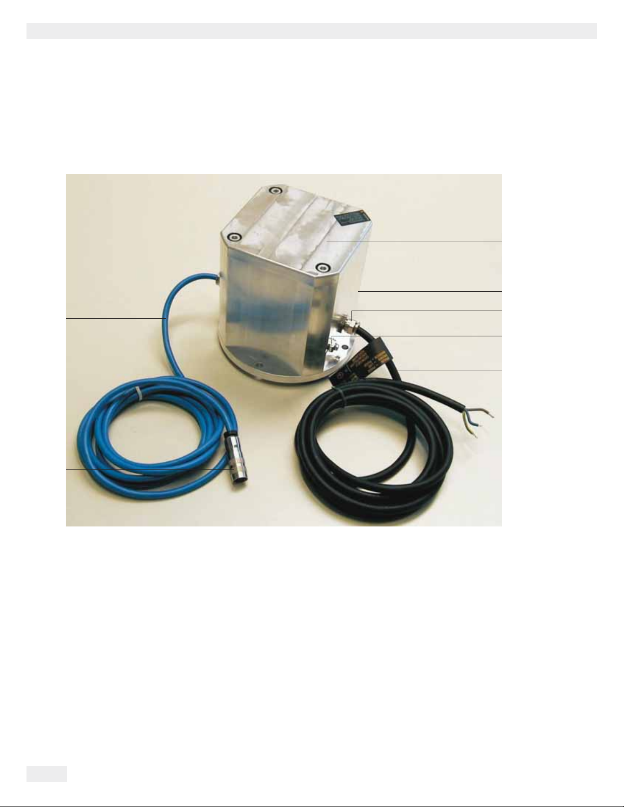
General View of the Equipment . . . . . . 2
User Information . . . . . . . . . . . . . . . . . 3
Contents. . . . . . . . . . . . . . . . . . . . . . . . 4
Intended Use . . . . . . . . . . . . . . . . . . . . 4
Safety Precautions . . . . . . . . . . . . . . . . 4
Equipment Supplied . . . . . . . . . . . . . . . 5
Installation. . . . . . . . . . . . . . . . . . . . . . 6
Documents . . . . . . . . . . . . . . . . . . . . . . 9
Intended Use
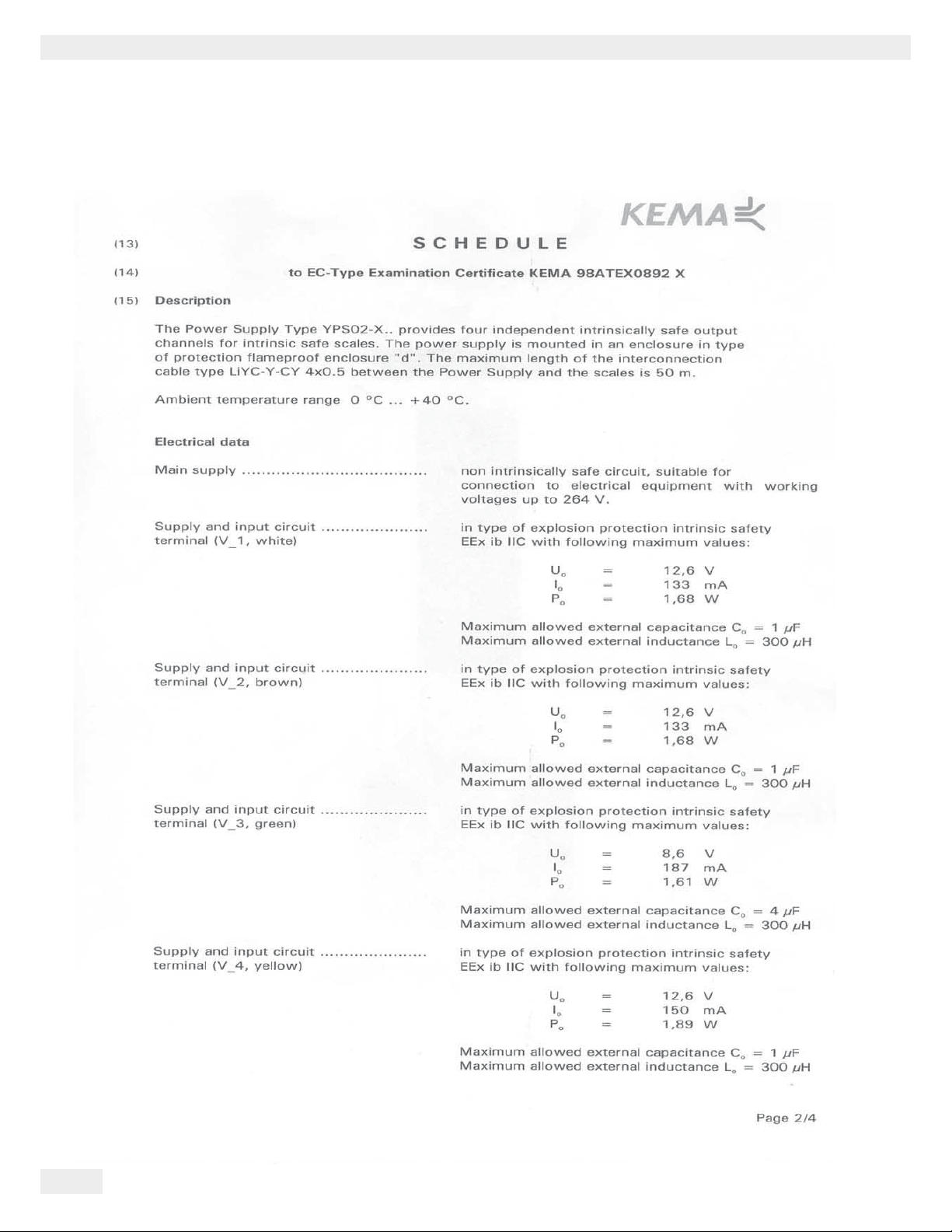
The pressure-capsulated power supplies (type YPS02-XDR and YPS02-XGR)
are suitable for use in potentially explosive atmospheres of zone 1 (gas) and
zone 20 (dust). For more information, please see the included EC Type
Examination Certificate, number KEMA 98ATEX0892X, including
amendment 1. The standard length of the power supply cable as well as the
DC connection cable is 3 m. Special lengths are available upon request.
Safety Precautions
The power supply corresponds to stipulated safety requirements. Incorrect
use can lead to injury to persons and damage to property. The power supply
should only be installed and operated by qualified personnel. All device
safety and warning information must be followed in their entirety during
installation, operation, maintenance and repairs. Standards, ordinances,
health and safety regulations as well as environmental protection regulations
of the respective country must be observed and followed. These instructions
should be understandable to all those concerned and the documents must
always be to hand. Furthermore, the warning and safety information
supplied with any connected electrical equipment, such as balances or
peripheral devices, must be observed as well. These warnings and safety
precautions must be supplemented by the operator as required. The
manufacturer is not responsible for any damages caused by non-compliance
with warnings or safety information.
All operating personnel must be informed of any additions to these
instructions.
Always keep the equipment freely accessible.
General installation specifications
If the equipment is modified by anyone other than persons authorized by
Sartorius, authorization is withdrawn and all claims under the manufacturer’s
warranty are forfeited. The installation of the power supply in a potentially
explosive atmosphere must be carried out by a qualified electrician.
A qualified electrician is deemed to be a person who is familiar with the
assembly, start-up and operation of the equipment. The qualified electrician
has the appropriate qualifications and is familiar with the relevant conditions
and regulations. If necessary, speak to the supplier or Sartorius Service
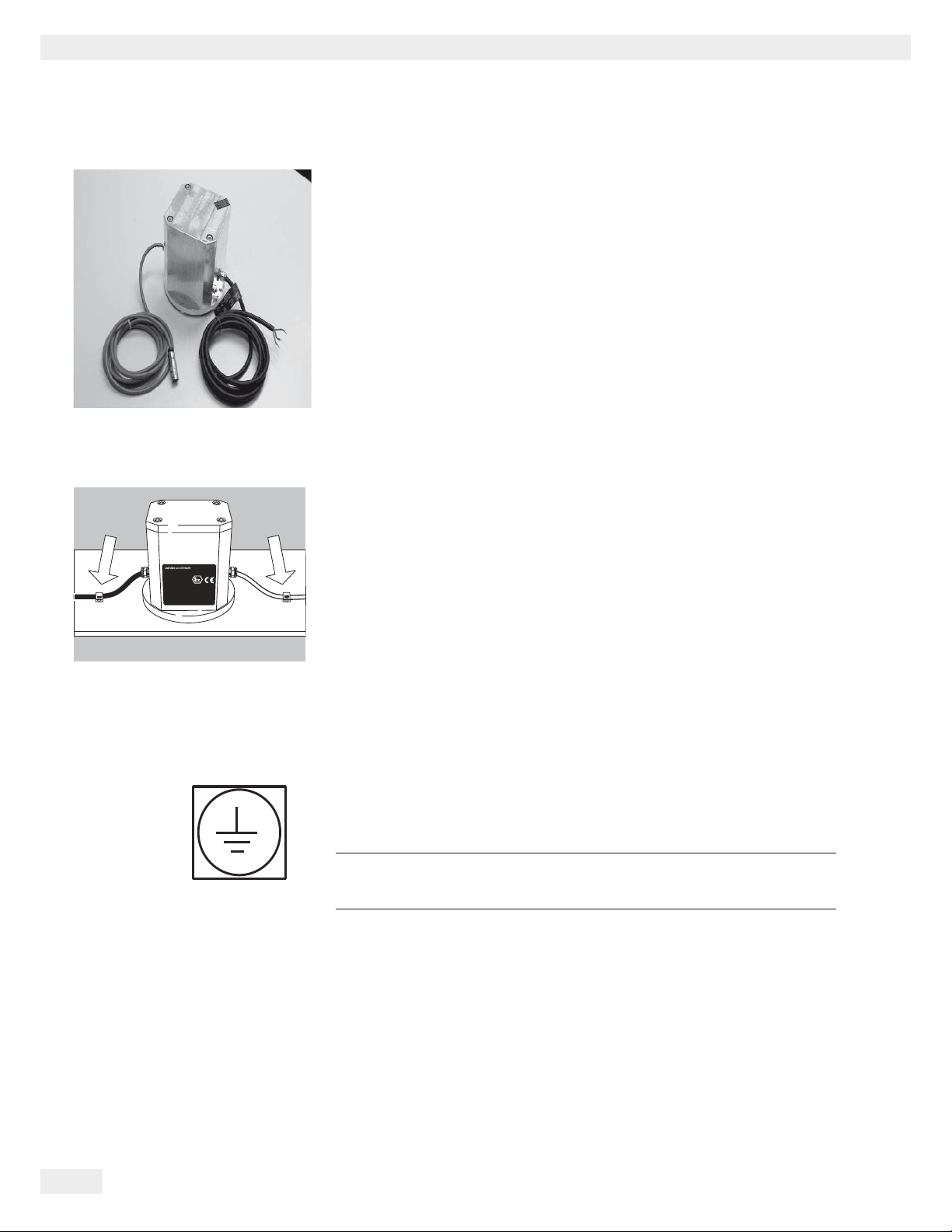
Center. Avoid generating static electricity. Connect an equipotential bonding
conductor.
Disconnecting the equipotential bonding cables is not permitted. The
position is marked with a grounding symbol. The grounding cable must have
a minimum cross-section of 4 mm2. Connect all equipment and peripheral
devices to be connected to the power supply to the equipotential bonding
conductor.
Do not unnecessarily expose the power supply to extreme temperatures,
aggressive chemical vapors, moisture, shocks, or vibration.
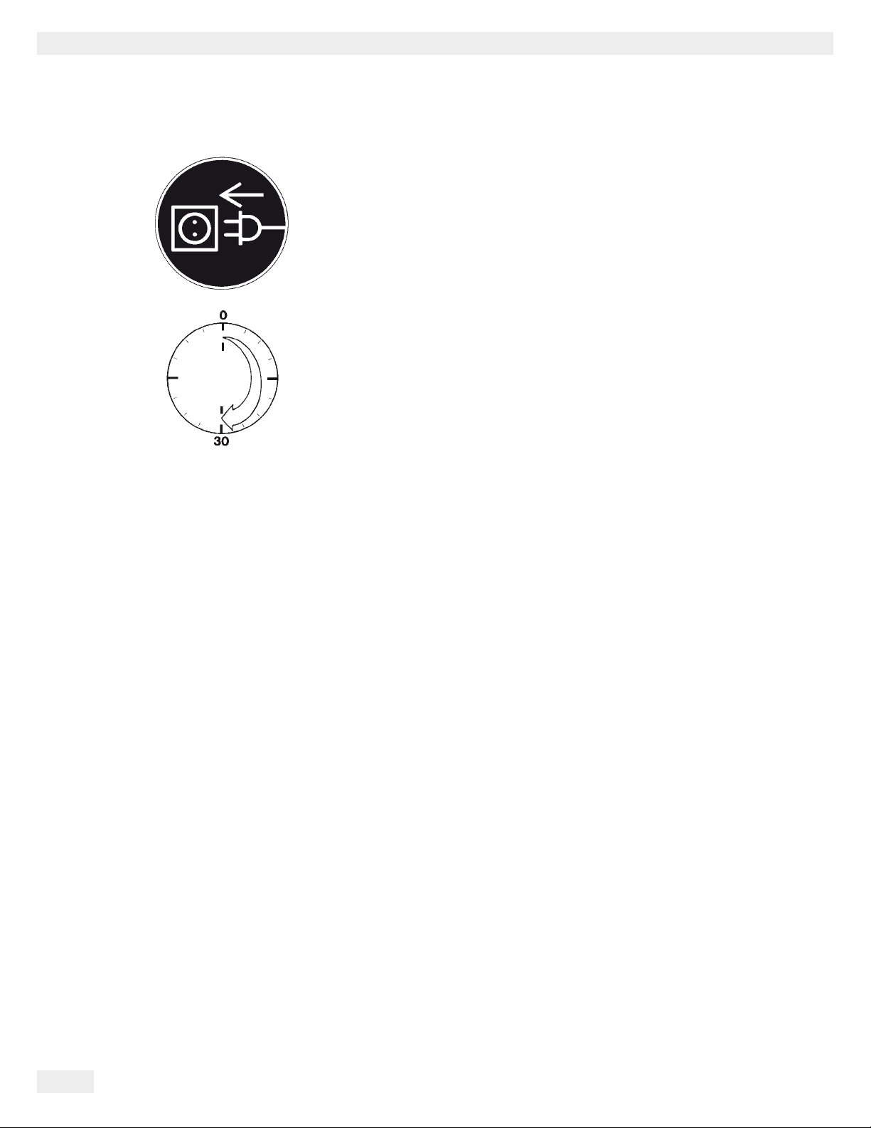
The power connection must be made in accordance with the regulations
applicable in your country. If necessary, speak to the supplier or Sartorius
Service Center. Any installation work that does not conform to the
instructions in this manual results in forfeiture of all claims under the
manufacturer’s warranty.

YPS02-X.. Installation Instructions 5
For the User
The YPS02-XDR and YPS02-XGR power supply types have a pressure-encapsulated aluminum housing, a power cable and a DC
connection cable. The DC connection cable includes four intrinsically safe electrical circuits. The only difference between these
two models is the type of power cable (see below).
3The power supply should only be opened by trained personnel with the power disconnected.
If the power supply must be opened in a potentially explosive atmosphere, you must wait at least 10 minutes after the
power has been disconnected before opening the device so that the internal capacitors have had a chance to discharge
safely. Danger to life: do not touch conductive parts of the power supply wiring!
Chemicals (e.g. gases or liquids) that can corrode and damage the inside or outside of the devices or cables must be
kept away from the equipment. Handle the equipment and any accessories in accordance with the IP rating (EN
60529). The casing on all connecting cables as well as the casing on the wires of the internal cabling is made of PVC
or of rubber.
The power supplies are designed to be connected to supply voltages of 100-240 VAC (± 10%), 50/60 Hz. The devices
meet the requirements for IP65 as per EN 60529.
Only use original Sartorius spare parts.
The power cable as well as the DC connection cable are not designed for flexible installation and must be protected
accordingly against tensile strain. A special version for flexible installation is available upon request.
Ambient temperature, operating temperature: 0°C ... +40°C
Storage and shipping temperature: - 20°C ... +60°C
Models:
YPS02-XDR Power supply for use in the EU (except for GB)
Power line: H07RN-F3G1.5 ( 3 x 1.5 mm²), Color of outer sheath: black
YPS02-XGR Power supply for use in GB
Power line: cable with steel wire network ( 3 x 1.5 mm²), color of outer sheath: clear (transparent)
Safety Precautions
Equipment Supplied
tRemove the power supply from the packaging.
The equipment supplied includes the following:
– YPS02-XDR Power supply for use in the EU (except for GB)
or
– YPS02-XGR Power supply for use in GB
yAfter unpacking the power supply, inspect the device immediately for any visible damage.
If there is any damage, do not operate the device and contact your Sartorius dealer.

Installation
Connecting the Device to AC Power
!Before startup, make sure that the power cable is properly connected to the power
outlet. In particular, the protective conductor must be connected to the housing
of the power supply.
Connect all devices via their equipotential bonding conductor terminals to the
equipotential bonding conductor. Installation must be carried out properly by
trained personnel and according to the standards of the technology.
!The system should only be operated for the first time when it is certain that the
area is not potentially explosive. If deviations are evident during startup due to
transport damage, the system should be disconnected from the power supply and
Service should be contacted (no display, no backlighting despite weight value
display, no reproducibility of the weight value, no stability in the display, etc.)
!Cabling:
– Both cables should be laid fixed
– Flexible cabling with screws available upon request
tCheck the supply voltage/frequency and plug design.
Contact your Sartorius dealer if they do not match.
!When operating a balance in an explosive area:
– Follow all current standards and regulations for the installation of devices in the
explosive area.
– Device installation should be carried out by trained personnel and checked
properly.
!Before startup, connect the linked devices to a central equipotential busbar.
hOnly use cables and cable lengths approved by Sartorius,
cables not provided by Sartorius are the responsibility of the operator.
6YPS02-X.. Installation Instructions
Installation

Secure power supply cable
FC…BBE/CCE model: FC…EDE model: FCA model:
YPS02-X.. Installation Instructions 7
tInsert the plug of the blue explosion proof power supply cable into the balance and
secure the connection using the ring nut.
!Make sure that the power supply cable is positioned and secured so that it cannot be
damaged.
yAn explosion proof terminal plug for the power cable (primary side) of the YPS02-X..
power supplies is not a part of the equipment supplied (open cable ends).
hWhen using a rechargeable battery for saving data:
Data is saved in a battery-backed memory.
Allow the device to be connected for one day to the power for initial startup.
When the balance is disconnected from power, the saved data is retained in
memory for approximately three months. In standby operation, data is stored
via the power supply. Log data should be printed before storing for long
periods of time.
Establishing the potential equalization connection (ground connection)
tConnect the balance and power supply to a equipotential busbar using a ground
connection cable (not part of the equipment supplied).
The metal housing of the power supply is also grounded via the protective conductor
of the power cable. The metal housing of the balance is connected to the power supply
via the shielding braid of the connection cable.
Installation

Connecting Electronic Devices (Peripherals)
!Make absolutely sure that the balance is unplugged from the power supply before
connecting/disconnecting a peripheral device (printer or PC) to or from the
interface port.
Warm-up Time
To return precise results, the balance must warm up for at least 30 minutes after
initial connection to the power supply.
Only after this time will the balance have reached the required operating
temperature.
Using a verified balance in legal metrology:
yMake sure to allow the device to warm up for at least 24 hours after initial
connection to the power supply.
8YPS02-X.. Installation Instructions
Installation

Documents
YPS02-X.. Installation Instructions 9
Documents

10 YPS02-X.. Installation Instructions
Documents

YPS02-X.. Installation Instructions 11
Documents

12 YPS02-X.. Installation Instructions
Documents

YPS02-X.. Installation Instructions 13
Documents

14 Installationsanleitung YPS02-X..
Übersichtsdarstellung
Pos.Bezeichnung
1 Netzgerät
2 Typenschild
3 Kabelverschraubung
4 PA-Anschluss (Erdungsklemme)
5 Netzanschlusskabel
6 Stecker für den Anschluss an ein eigensicheres Gerät
7 Eigensicheres DC-Kabel
1
2
3
4
5
6
7

Installationsanleitung YPS02-X.. 15
Benutzerhinweise
Zu dieser Installationsanleitung
tDiese Installationsanleitung aufmerksam und vollständig lesen,
bevor das Gerät zum ersten Mal in Betrieb genommen wird.
tDie Installationsanleitung aufmerksam lesen und die Sicherheitshinweise beachten.
tDie Installationsanleitung ist ein Teil des Produktes.
Die Installationsanleitung gut erreichbar und sicher aufbewahren.
tBei Verlust der Anleitung Ersatz anfordern oder die aktuelle Anleitung von der Sartorius Website
www.sartorius.com herunter laden.
Warnzeichen/Gefahrensymbole
Warn- und Gefahrensymbole in dieser Anleitung:
Gefahr durch Stromschlag
2Körperschaden oder Tod als Folge
Warnung vor einem möglichen Körperschaden,
3Gesundheitsrisiko oder Gefahr von Sachschäden
hHinweis für nützliche Informationen und Tipps
Zeichenerklärung
Folgende Symbole werden in dieser Anleitung verwendet:
tsteht vor Handlungsanweisungen
ybeschreibt, was nach einer ausgeführten Handlung geschieht
1. Handlungen in einer bestimmten Reihenfolge ausführen
2.
– steht vor einem Aufzählungspunkt
Benutzerhinweise

16 Installationsanleitung YPS02-X..
Inhalt
Inhalt
Übersichtsdarstellung. . . . . . . . . . . . . 14
Benutzerhinweise . . . . . . . . . . . . . . . . 15
Inhalt . . . . . . . . . . . . . . . . . . . . . . . . . 16
Verwendungszweck . . . . . . . . . . . . . . 16
Sicherheitshinweise . . . . . . . . . . . . . . 16
Lieferumfang . . . . . . . . . . . . . . . . . . . 17
Installation. . . . . . . . . . . . . . . . . . . . . 18
Dokumente. . . . . . . . . . . . . . . . . . . . . 21
Verwendungszweck
Die druckgekapselten Netzgeräte Typ YPS02-XDR und YPS02-XGR sind
geeignet zum Einsatz in explosionsgefährdeten Bereichen der Zone 1
(Gase) und Zone 20 (Stäube). Weitere Informationen sind der beigefügten
EG-Baumusterprüfbescheinigung ( EC-Type Examination Certificate)
Nummer KEMA 98ATEX0892X einschließlich der Ergänzung 1 (Amend-
ment 1) zu entnehmen. Die Länge des Netzkabels sowie des DC-
Anschlusskabels beträgt standardmäßig 3m. Sonderlängen sind auf Anfra-
ge möglich.
Sicherheitshinweise
Das Netzgerät entspricht den vorgeschriebenen Sicherheits-
bestimmungen. Ein unsachgemäßer Gebrauch kann zu Schäden an
Personen und Sachen führen. Das Netzgerät nur von qualifiziertem
Personal installieren und betreiben lassen. Die Sicherheits- und
Warnhinweise in ihrer Gesamtheit bei der Installation, beim Betrieb,
bei der Wartung und Reparatur des Gerätes befolgen.
Normen, Verordnungen sowie Unfallverhütung und den Umweltschutz
des
jeweiligen Landes befolgen und einhalten.
Diese Hinweise sollten alle Beteiligten verstehen und die
Dokumente stets griffbereit sein. Die Sicherheits- und Warnhinweise in
den Unterlagen der angeschlossenen elektrischen Betriebsmittel wie z.B.
für Waagen oder Zubehör befolgen. Diese Sicherheits- und Warnhinweise
muss der Betreiber ggf. ergänzen. Der Hersteller kann nicht für Schäden
verantwortlich gemacht werden, die infolge von Nichtbeachtung der
Sicherheitshinweise und Warnungen verursacht werden
Das Bedienpersonal entsprechend einweisen.
Die Einrichtungen immer frei zugänglich halten!
Allgemeine Bestimmungen für die Installation
Jeder Eingriff in die Geräte (ausser durch von Sartorius autorisierte Perso-
nen) führt zum Verlust der Zulassung und aller Garantieansprüche. Die
Installation des Netzgerätes im explosionsgefährdeten Bereich muss von
einer Elektrofachkraft erfolgen. Als Elektrofachkraft gilt eine Person, die
mit der Montage, Inbetriebnahme und Betrieb der Anlage vertraut ist. Die
Elektrofachkraft verfügt über die entsprechende Qualifikation, die ein-
schlägigen Bestimmungen und Vorschriften sind Ihr bekannt. Bei Bedarf
den Händler oder Sartorius-Kundendienst ansprechen. Elektrostatische
Aufladung vermeiden. Potenzialausgleichsklemme anschließen.
Eine Unterbrechung der Potenzialausgleichsleitungen ist untersagt. Die
Stelle ist mit einem Erdungssymbol gekennzeichnet. Das Erdungskabel
muss einen Mindestquerschnitt von 4mm2haben. Alle Geräte und Zube-
hörteile, die an das Netzgerät angeschlossen werden mit dem Potenzial-
ausgleich (PA) verbinden.
Das Netzgerät nicht unnötig extremen Temperaturen, aggressiven chemi-
schen Dämpfen, Feuchtigkeit, Stössen und Vibrationen aussetzen.
Der Netzanschluss muss gemäß den Bestimmungen Ihres Landes erfolgen.
Bei Bedarf den Händler oder Sartorius-Kundendienst ansprechen. Bei
unsachgemäßer Installation entfällt die Gewährleistung.

Installationsanleitung YPS02-X.. 17
Für den Benutzer
Die Netzgeräte Typ YPS02-XDR und YPS02-XGR bestehen aus einem druckgekapselten Aluminiumgehäuse, einem Netzkabel
und einem DC-Anschlusskabel. Das DC-Anschlusskabel beinhaltet vier eigensichere Stromkreise. Diese beiden Modelle unter-
scheiden sich nur im Typ des Netzkabels (siehe unten).
3Das Netzgerät darf nur in spannungslosem Zustand von hierfür geschulten Fachkräften geöffnet werden!
Muss das Netzgerät im explosionsgefährdeten Bereich geöffnet werden, so muss mindestens 10 Minuten nach
dem Spannungslosschalten gewartet werden, bevor mit dem Öffnen begonnen wird, damit die internen Konden-
satoren sicher entladen sind. Beim Berühren leitender Teile der netzseitigen Verdrahtung besteht Lebensgefahr!
Chemikalien (z.B.: Gase oder Flüssigkeiten), die die Geräte oder Kabel innen oder aussen angreifen und beschädi-
gen können, sind fernzuhalten. Den IP Schutz des Gerätes und des Zubehörs einhalten (DIN EN 60529). Die
Ummantelung aller Verbindungskabel sowie die der Litzen der inneren Verdrahtungen bestehen aus PVC-Material
oder aus Gummi.
Die Netzgeräte sind geeignet zum Anschluss an Netzspannungen von 100-240Vac (± 10%), 50/60Hz. Die Geräte
erfüllen die Anforderungen für IP65 gemäß EN 60529.
Nur Original-Sartorius-Ersatzteile verwenden!
Das Netzkabel sowie das DC-Anschlusskabel sind nicht für flexible Verlegung geeignet und müssen entsprechend
gegen Zugbelastung gesichert werden. Auf Anfrage kann eine Spezialversion für flexible Verlegung der Kabel
geliefert werden.
Umgebungstemperatur, Betriebstemperatur: 0°C ... +40°C
Lager- und Transporttemperatur: - 20°C ... +60°C
Modelle:
YPS02-XDR Netzgerät zum Einsatz in der EU (außer GB)
Netzleitung: H07RN-F3G1,5 ( 3 x 1,5mm²), Außenmantelfarbe: schwarz
YPS02-XGR Netzgerät für den Einsatz in GB
Netzleitung: Kabel mit Stahldrahtgeflecht ( 3 x 1,5mm²), Außenmantelfarbe: klar (durchsichtig)
Lieferumfang
tDas Netzteil aus der Verpackung nehmen.
Folgende Einzelteile werden mitgeliefert:
– YPS02-XDR Netzgerät zum Einsatz in der EU (außer GB)
oder
– YPS02-XGR Netzgerät für den Einsatz in GB
yDas Netzgerät sofort nach dem Auspacken auf eventuell sichtbare Beschädigungen überprüfen.
Im Fall einer Beschädigung das Gerät nicht in Betrieb nehmen, den Sartorius-Händler ansprechen.
Sicherheitshinweise

18 Installationsanleitung YPS02-X..
Installation
Installation
Netzanschluss herstellen
!Vor der Inbetriebnahme muss sichergestellt sein, dass das Netzkabel ordnungs-
gemäß am Netz angeschlossen ist. Insbesondere muss der Schutzleiter mit dem
Gehäuse des Netzgeräts verbunden sein.
Alle Geräte über die an den Geräten vorhandenen Potentialausgleichsklemmen
an den Potentialausgleich (PA) anschließen. Die Installation muss von einer dafür
ausgebildeten Fachkraft vorschriftsmäßig und nach den Regeln der Technik
durchgeführt werden.
!Die Anlage erstmalig nur dann in Betrieb nehmen, wenn sichergestellt ist, dass
der Bereich nicht explosionsgefährdet ist. Zeigen sich bei dieser Inbetriebnahme
durch Transportschäden Abweichungen, so ist die Anlage vom Netz zu trennen
und der Service zu informieren (keine Anzeige, keine Hinterleuchtung trotz
Gewichtswertanzeige, keine Reproduzierbarkeit des Gewichtswertes, kein Still-
stand in der Anzeige, etc.).
!Kabelverlegung:
– beide Kabel fest verlegen
– flexible Kabelverlegung mit Verschraubung auf Anfrage
tNetzspannung/Netzfrequenz und Steckerausführung überprüfen.
Bei Nichtübereinstimmung Ihren Sartorius-Händler ansprechen.
!Beim Betrieb der Waage im Ex-Bereich beachten:
– Derzeit gültige Normen und Vorschriften für die Installation von
Geräten im Ex-Bereich einhalten.
– Die Installation der Geräte von einem Fachmann durchführen und vorschriftsmä-
ßig überprüfen lassen.
!Vor Inbetriebnahme die miteinander verbundenen Geräte an eine zentrale
Potenzialausgleichsschiene anschließen!
hNur von Sartorius freigegebene Kabel und Kabellängen verwenden,
Nicht von Sartorius gelieferte Kabel unterliegen der Verantwortung des
Betreibers.

Installationsanleitung YPS02-X.. 19
tBuchse des blauen Ex-Netzgerätekabels in die Waage einsetzen und die
Verbindung mit dem Schraubring sichern.
!Netzanschlusskabel geschützt verlegen, so dass es nicht beschädigt werden kann.
yEx-Anschlussstecker für das Netzkabel (primärseitig) der Netzgeräte YPS02-X..
ist nicht Bestandteil des Lieferumfangs (offene Kabelenden).
hBei Verwendung eines Akkus für die Speicherung von Daten:
Die Speicherung der Daten erfolgt in einem akkugepufferten Speicher.
Bei Erstinbetriebnahme das Gerät einen Tag lang am Netz lassen.
Beim Trennen der Waage vom Netzanschluss bleiben die ermittelten
Daten ca. drei Monate gespeichert. Im Standby-Betrieb erfolgt die Daten-
haltung über die Netzversorgung. Vor längerer Lagerung Protokolldaten
ausdrucken.
Potenzialausgleichsanschluss herstellen (Erdungsanschluss)
tWaage und Netzgerät mit einem Masseverbindungskabel
(nicht im Lieferumfang) an zentrale Potenzialausgleichsschiene anschließen.
Außerdem ist das metallische Gehäuse des Netzgerätes über den Schutzleiter
des Netzkabels geerdet. Das metallische Gehäuse der Waage ist über das
Schirmgeflecht des Verbindungskabels zum Netzgerät verbunden.
Netzanschlusskabel befestigen
FC…BBE/CCE model: FC…EDE model: FCA model:
Installation

20 Installationsanleitung YPS02-X..
Installation
Anschluss von elektronischen Komponenten (Peripherie)
!Vor Anschluss oder Trennen von Zusatzgeräten (Drucker, PC) an die Daten-
schnittstelle muss die Waage unbedingt vom Netz getrennt werden
Anwärmzeit
Um genaue Resultate zu liefern, benötigt die Waage eine Anwärmzeit von
mindestens 30 Minuten nach erstmaligem Anschluss an das Stromnetz.
Erst dann hat die Waage die notwendige Betriebstemperatur erreicht.
Geeichte Waage im eichpflichtigen Verkehr einsetzen:
yAnwärmzeit von mindestens 24 Stunden einhalten nach erstmaligem
Anschluss an das Stromnetz.
This manual suits for next models
2
Table of contents
Languages: