manuals.online logo
Brands
  1. Home
  2. •
  3. Brands
  4. •
  5. Pulsar
  6. •
  7. Power Supply
  8. •
  9. Pulsar AWZ 201 User manual

Pulsar AWZ 201 User manual

PSU-B-13,8V/L-2A/1/EL-TR-17Ah/MC
AWZ 201
v.1.0
Linear, buffer type power supply
EN
Release: 1 dated
12.10.2011
Supersedes the release: ………
2
TABLE OF CONTENTS:
1. Technical description
2. Installation
3. Handling and operation
4. Maintenance
1. Technical description.
The buffer power pack is dedicated for uninterrupted power supply for the equipment requiring the
stabilized voltage 12V DC (±15%). The linear stabilizing system applied in the equipment delivers the voltage with
lower level of noise and shorter response time for the interference as is the case where a pulse stabilizer is
applied. The power pack delivers the voltage in buffer work Uout = 12.8 V ÷ 13.8 V DC, with the total current
capacity of 2 A. In the case of voltage decay, the immediate switching to power supplies from battery takes place
Caution:
Using AWZ200 Power Supply for CCTV, KD, SSWiN or other similar applications
demands using the MZN1 overvoltage module in the output DC stage of Power Supply.
Figure 1. Block diagram of the power pack.
3
Technical parameters
Power supply voltage
230V AC, 50 Hz (-15%/+10%)
Transformer TR 50 VA
Output voltage Uout *12.8 V ÷ 13.8 V DC
13.8 V DC – rated
13.4 V DC @ 2A
Output current Iout Imax – 2A (const.)
Power 28 W
SCP short-circuit protection
I-st grade - 200% ÷ 250%
of supply power – limitation of
current and/or fuse failure in the battery circuit (fuse-
element replacement required)
II – nd. grade - 110% ÷ 150% (@25ºC÷65ºC)
of supply
power – current limitation with the PTC automatic
fuse, manual restart (disconnection of the DC output
circuit)
OLP overload protection
110% ÷ 150% (@25ºC÷65ºC) of
supply
power –
current limitation with the PTC automatic fuse,
manual restart (disconnection of the DC output
circuit)
Battery charging current Iacc (max) = 1.4 A @ Iout =0A
0,3A / 24h (Iśr/24h)
F2 Fuse in the transformer primary circuit T 315 mA
(250 V)
Transformer primary circuit current - max 280 mA @ 2 A
(-15%, + 10%)
Transformer thermal protection 130
o
C
F1 Fuse in the battery circuit F 4A
Battery 17 Ah/12V SLA
TAMPER output service reliability - max 500 mA @ 30 V DC max.
Enclosure IP IP 20
Operating temperature - 10
o
C ÷ 40
o
C
Relative humidity - max 90 [%] (max.)
Dimensions (WxHxD) 235 x 305 x 98 (90 + 8)
[±2] [mm]
Weight 2.9 kg net
3,0 kg gross
*In buffer operation
Tab. 1 - Power pack technical parameters.
Figure 2. Current and voltage characteristics of the power pack.
0 0,2 0,4 0,6 0,8 1 1,2 1,4 1,6 1,8 2 2,2 2,4 2,6 2,8
12,2
12,4
12,6
12,8
13
13,2
13,4
13,6
13,8
Diagram Uout(Io)
Uwy
I[A]
U[V]
Uout/Io diagramUout/Io diagram
4
Figure 3. General view of the power pack.
5
[1] ~AC~
joint
[2] F1
fuse in transformer circuit
[3] Battery outputs
[4] Red diode
optical signalling
[5] Green diode
optical signalling
[6] Outputs
Joint (Tab. 3)
[7] P1
Voltage adjustment
[8] 230 – 0V
Battery joint 230V/AC
[9] F2
Transformer primary circuit fuse
[10] Joint (with yellow-green
PE protective
conductor)
Tab. 2. Description of designations from the figure 3.
2. Installation.
The buffer power pack is dedicated for assembly by the qualified assembly man, holding relevant
certificates (as required and necessary for the specific country), permissions and authorizations for making
connections in 230 V AC systems and LV systems. The equipment should be assembled in non-open-space
rooms, in accordance with environment class II, with standard air relative humidity (RH – 90% maximum, without
condensation) and the temperature within the range from -10°C to +40°C. The power pack should be operated in
the vertical position such that the free air convection is ensured through the ventilation openings of the enclosure.
Prior to entering for installation, the balance of power pack loads should be drawn up. During the normal
operation the sum of currents consumed by the consumers may not exceed 2A, with the incorporation of
the battery charging current.
As the power pack is designed for the constant operation, the circuit breaker is not included and this is why the
proper and appropriate shock protection in the power supply circuit must be ensured. Also the users should be
informed about the method of disconnecting the power pack from the power supply voltage (most frequently
through the separation and designation of the relevant fuse in the fuse box). The wiring system should be
completed in accordance with the applicable norms, standards and regulations.
Caution: Prior to entering for installation make sure that the voltage in the 230 V power supply circuit
is disconnected.
1. Assemble the power pack in any place and connect the connection leads.
2. Remove the power grid fuse protecting the transformer primary circuit.
3. Connect the 230 V power supply conductors to the 230 V AC transformer terminals [8]. The earthing conductor
should be connected to the terminal designated with the earthing symbol [10]. The connection should be made
by means of the three-wire cable (with yellow-green PE protective conductor). The power supply conductors
should be run as far as the relevant terminals of the connection board, through the insulation pass.
Caution: Pay special attention when completing the shock protection circuit: the yellow-green PE
protective conductor of the power supply cable must be connected from one side to the terminal
designated in the power pack enclosure. The operation of the power pack without the shock
protection circuit properly completed and technically operable IS NOT ADMISSIBLE!
The operation without such circuit threatens with damage to the equipment or electric shock.
[6] PL
+OUT
-OUT + Vcc output
- GND output
TAMPER Sabotage prevention switch
contacts – NC
Tab. 3.
Description of the output joint.
6
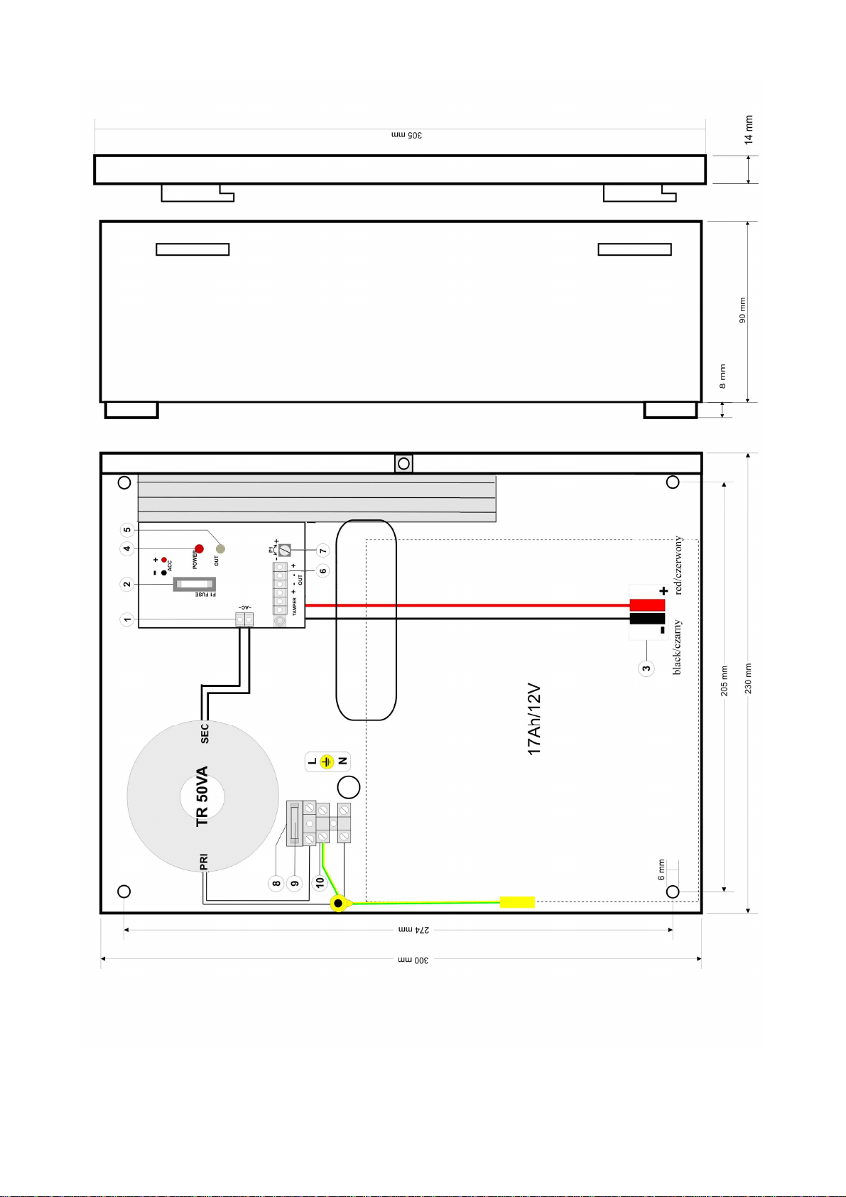
4. Connect the leads of the consumers to joints OUT + and - of the joint box on the power pack board [6].
(Optionally connect the MZN1 module between +OUT- and load).
5. Activate the 230 V AC power supply and insert the power network fuse protecting the transformer primary circuit
[9]. Check the optical signalling of the power pack operation. The output voltage of the unloaded power pack is
equal to ~ 13.8 V DC. The voltage may fluctuate from 12.8 V to 13.8 V DC during battery charging.
6. Connect the battery in accordance with the designations [3] with colours. After this operation is completed, the
voltage appears in the output of the power pack, which is signalled by the green diode on.
7. Perform the power pack test checking the optical signalling [4] [5]: - the disconnection of the voltage 230 V AC
through the removal of the fuse from the transformer socket will be signalled by the red diode going off.
8. Following the assembly and checking the correctness of operation, the enclosure may be locked.
3. Handling and operation.
3.1. Power pack operation signalling.
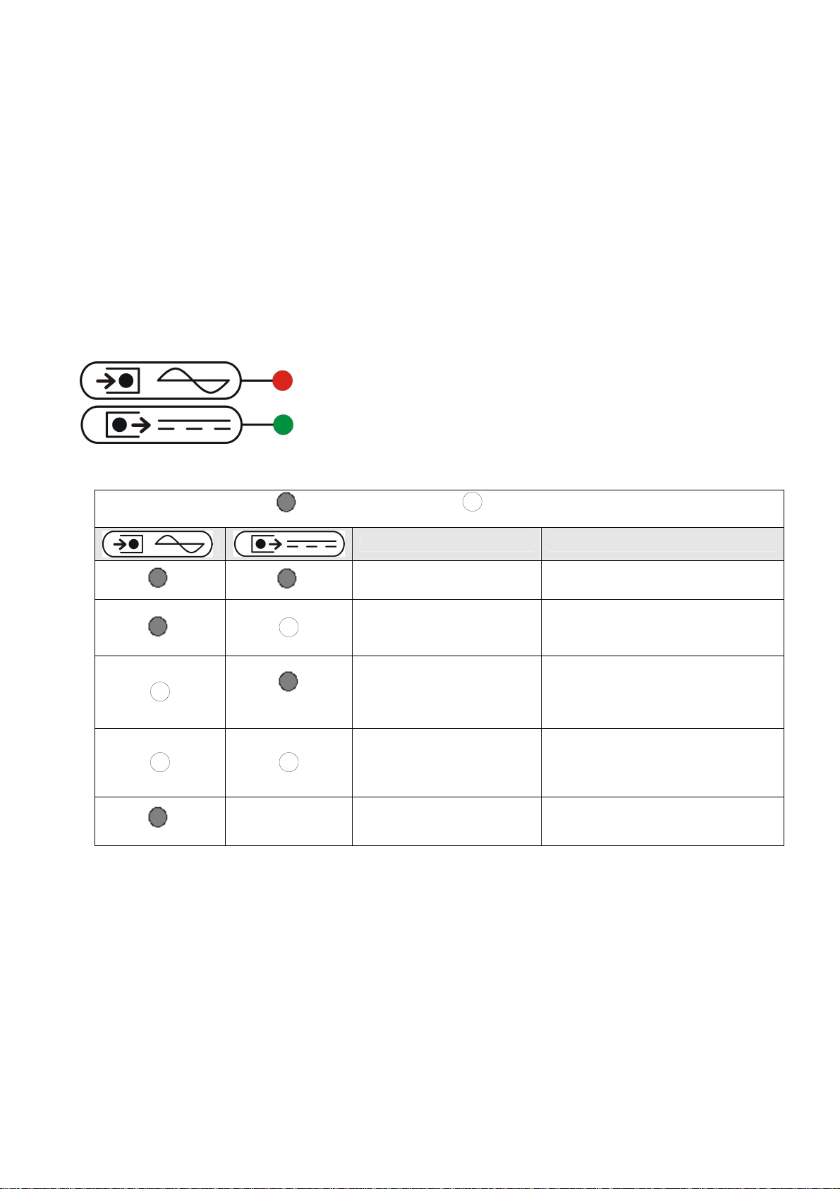
The unit is equipped with the optical signalling of operation states:
Red diode:
on -the power pack is supplied with voltage 230V AC
off -the power pack is not supplied with voltage 230V
AC
Green diode
on – DC voltage at the output of the power pack
off – DC voltage missing at the output of the power
pack
- on - off
Description Comments
Proper state of operation
Output overloaded or short
circuited - check cabling and consumers
- if the battery is connected, check
battery fuse
The absence of power
supply from the power
network, operation from
battery
- check transformer fuse
The absence of voltage at
the output - check cabling and consumers
- check transformer fuse
- check battery fuse
flickers Output overloaded - lower the consumption of current by
consumers
Tab. 4 Optical signalling.
3.2. Operation from the battery.
Starting the operation from the battery.
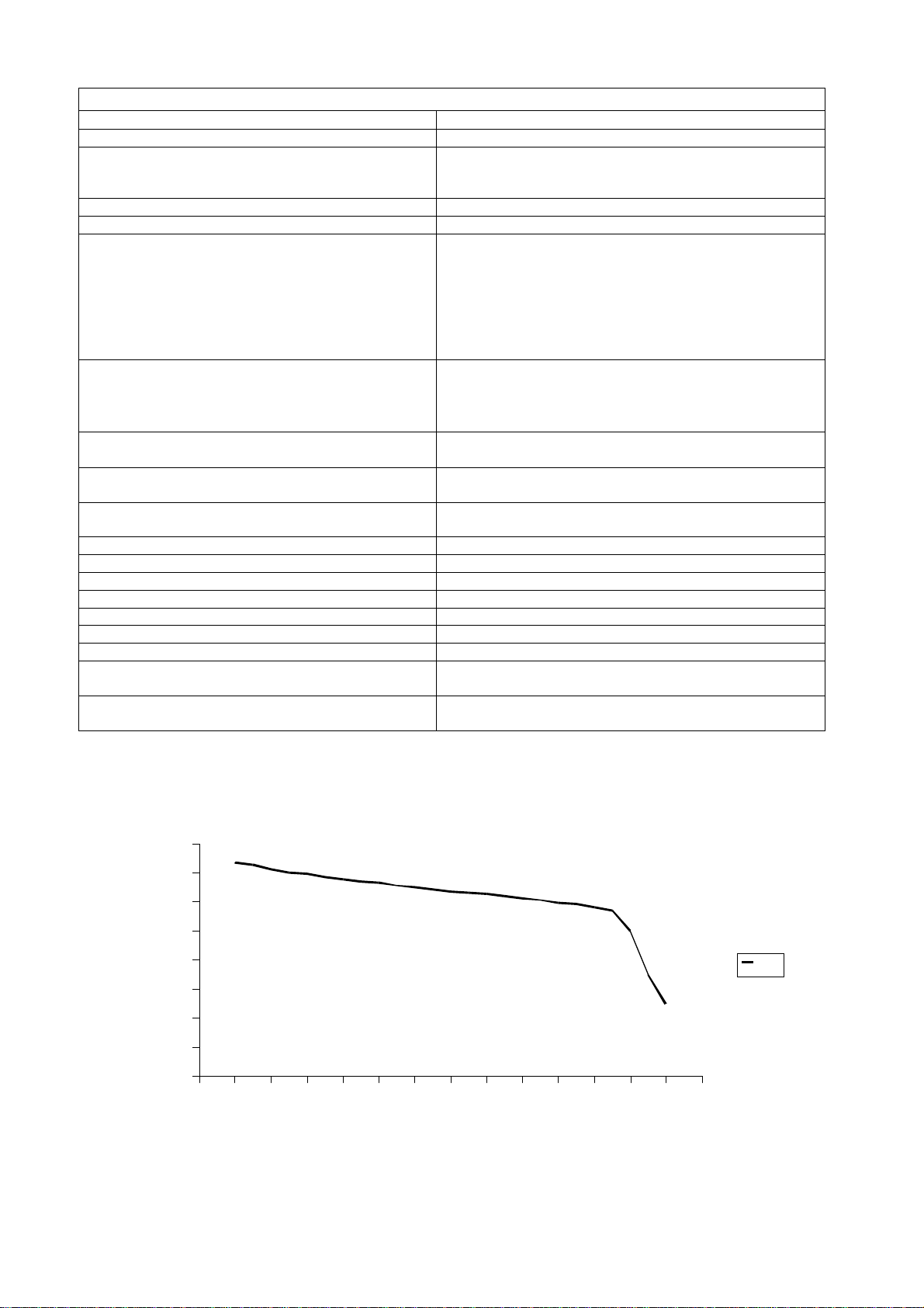
The time of operation with supplies from battery depends on the battery capacity, the extent of charging
and the load current. For example, for the typical, fully charged battery with capacity of 17 Ah and load current 2A,
the maximum operation time safe for the battery is approximately 8h.
Starting the power pack from the battery: after connecting the battery in accordance with the
designations [3], the voltage appears on the output terminals of the power pack.
The limitation of the battery charging current.
The power pack is equipped with the battery charging current limitation to the value:
- Iacc (max) = 1.4 A with unloaded power pack Iout = 0A
- Iacc (aver.) = 0.3 A with power pack load with current Iout = 1.7 A
7
3.3. Procedures in the case of power pack overloading.
The power pack is equipped with the protection of the output stage with the application of the PTC polymer fuse.
When the power pack is loaded with current exceeding 2A (110%
÷150% P)
, the automatic disconnection of the
output voltage takes place which is signalled by the green diode going off. In such a case, the load should be
disconnected from the output of the power pack for the period of about 1 minute.
4. Maintenance.
All the maintenance duties may be performed following disconnection of the power pack from the power grid. The
power pack does not require any specific maintenance procedures, however, in the case of significant level of
dust, its interior should be cleaned with the compressed air.
When replacing the fuse, use only substitutes in conformity to originals.
8
WEEE MARK
The waste electric and electronic products do not mix with general household
waste. There are separate collection system for used electric and electronic
products in accordance with legislation under the WEEE Directive and is
effective only with EU.
Notice: The power supply unit is adapted for cooperation with the sealed lead-acid battery (SLA).After the operation period it must
not be thrown but recycled according to the applicable law.
GENERAL WARRANTY CONDITIONS
1. Pulsar K. Bogusz Sp.j. (manufacturer) grants a two-year quality warranty for the equipment starting from the date of
purchase placed on the purchase order.
2. Should such purchase order be missing when the claim is submitted the three-year guarantee period is counted from the
date of the manufacturing of the device.
3. The warranty includes free-of-charge repairing or replacing with a functional equivalent (the selection is made by the
manufacturer) of the malfunctioning device due to reasons attributable to the manufacturer including manufacturing and
material defects unless such defects have been reported beyond the warranty period (item 1 and 2).
4. The equipment subject to warranty is to be brought to the place where it was purchased or directly to the main office of
the manufacturer.
5. The warranty applies to complete equipment including the type of defect specified in writing using a properly filled
warranty claim.
6. Should the claim be accepted the manufacturer is obliged to render warranty repairs as soon as possible however not
later that within 14 days from the delivering of the equipment to the service centre of the manufacturer.
7. The repair period mentioned in item 5 may be prolonged if there is no technical capability to carry out the repairs and in
the case that the equipment has been accepted conditionally due to the failing of the warranty terms by the claimant.
8. All the services rendered by force of the warranty are carried out at the service centre of the manufacturer exclusively.
9. The warranty does not cover the defects of the equipment resulting from:
- reasons beyond the manufacturer's control
- mechanical damage
- improper storage and transport
- use that violates the operation manual or equipment application
- random events including lightning discharges failures of power networks fire flooding high temperatures and chemical
agents
- improper installation and configuration (at variance with the rules set forth in the manual)
10. Each confirmation of structural modifications or repairs carried out beyond the service centre of the manufacturer or any
modification of serial numbers or warranty labels results in the loss of the rights resulting from the warranty.
11. The liability of the manufacturer towards the buyer is limited to the value of the equipment determined according to the
wholesale prices suggested by the manufacturer on the day of purchase.
12. The manufacturer shall not be responsible for the defects that resulted from the damaging malfunctioning or inability to
operate the equipment particularly if such defects are the result of failing to abide by the recommendations and
requirements contained in the manual or the use of the equipment.
Pulsar K.
Bogusz Sp.j.
Siedlec 150,
32-744 Łapczyca, Poland
Tel. (+48) 14-610-19-40, Fax. (+48) 14-610-19-50
e-mail: biuro@pulsar.pl, sales@pulsar.pl
http:// www.pulsar.pl

Other Pulsar Power Supply manuals

Pulsar HPSBOC 11A12C User manual

Pulsar

Pulsar HPSBOC 11A12C User manual

Pulsar PSBS 5012D User manual

Pulsar

Pulsar PSBS 5012D User manual

Pulsar PSBOC751250 User manual

Pulsar

Pulsar PSBOC751250 User manual

Pulsar PSC13008 User manual

Pulsar

Pulsar PSC13008 User manual

Pulsar AWZ 230 User manual

Pulsar

Pulsar AWZ 230 User manual

Pulsar PSBS5012C User manual

Pulsar

Pulsar PSBS5012C User manual

Pulsar PSDC08128T User manual

Pulsar

Pulsar PSDC08128T User manual

Pulsar DIN 1210 User manual

Pulsar

Pulsar DIN 1210 User manual

Pulsar PSCV5012 User manual

Pulsar

Pulsar PSCV5012 User manual

Pulsar PSCU 08348SEP User manual

Pulsar

Pulsar PSCU 08348SEP User manual

Pulsar EN54-3A17 User manual

Pulsar

Pulsar EN54-3A17 User manual

Pulsar MSRD-13,8V/2,5A User manual

Pulsar

Pulsar MSRD-13,8V/2,5A User manual

Pulsar PSBOC501235 User manual

Pulsar

Pulsar PSBOC501235 User manual

Pulsar PS401230 User manual

Pulsar

Pulsar PS401230 User manual

Pulsar Zenith 140 User manual

Pulsar

Pulsar Zenith 140 User manual

Pulsar PSCL12050 User manual

Pulsar

Pulsar PSCL12050 User manual

Pulsar PSD520115 User manual

Pulsar

Pulsar PSD520115 User manual

Pulsar AWZ 500 User manual

Pulsar

Pulsar AWZ 500 User manual

Pulsar EN54C-LCD Series User manual

Pulsar

Pulsar EN54C-LCD Series User manual

Pulsar HPSG2H-12V5A-C User manual

Pulsar

Pulsar HPSG2H-12V5A-C User manual

Pulsar PS402415 User manual

Pulsar

Pulsar PS402415 User manual

Pulsar 276V/7A/2x40Ah/LCD User manual

Pulsar

Pulsar 276V/7A/2x40Ah/LCD User manual

Pulsar PSCLB13830 User manual

Pulsar

Pulsar PSCLB13830 User manual

Pulsar PSBEN 5012C/LCD User manual

Pulsar

Pulsar PSBEN 5012C/LCD User manual

Popular Power Supply manuals by other brands

SOtM sPS-1000 operating instructions

SOtM

SOtM sPS-1000 operating instructions

Akyga AK-ND-52 user manual

Akyga

Akyga AK-ND-52 user manual

Lumina Power CCPF-1500 Operation manual

Lumina Power

Lumina Power CCPF-1500 Operation manual

TEXIO PS-A Series instruction manual

TEXIO

TEXIO PS-A Series instruction manual

Antec HCP-750 user manual

Antec

Antec HCP-750 user manual

Kenwood PS-33 instruction manual

Kenwood

Kenwood PS-33 instruction manual

Huawei TP482000B Series user manual

Huawei

Huawei TP482000B Series user manual

ANSMANN DCPS-Netbook operating instructions

ANSMANN

ANSMANN DCPS-Netbook operating instructions

Nissei NS-28SW instruction manual

Nissei

Nissei NS-28SW instruction manual

Zennio ZN1PS-160MPA quick start guide

Zennio

Zennio ZN1PS-160MPA quick start guide

LionTec MPS-2300300 Operating	 instruction

LionTec

LionTec MPS-2300300 Operating instruction

Recom RACM18-ER/W Series Installation and operating instructions

Recom

Recom RACM18-ER/W Series Installation and operating instructions

Thermaltake Toughpower XT Series manual

Thermaltake

Thermaltake Toughpower XT Series manual

Juniper M10i installation instructions

Juniper

Juniper M10i installation instructions

Innovative SR750L user manual

Innovative

Innovative SR750L user manual

EVGA SuperNOVA 100 P5 manual

EVGA

EVGA SuperNOVA 100 P5 manual

Insta 60031020 operating instructions

Insta

Insta 60031020 operating instructions

Keysight Technologies N2779A user guide

Keysight Technologies

Keysight Technologies N2779A user guide

manuals.online logo
manuals.online logoBrands
  • About & Mission
  • Contact us
  • Privacy Policy
  • Terms and Conditions

Copyright 2025 Manuals.Online. All Rights Reserved.