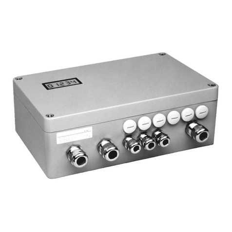
Sartorius PR 5211 Series User manual

Sartorius Mechatronics T&H GmbH, Meiendorfer Str. 205, 22145 Hamburg, Germany
Tel:+49.40.67960.303 Fax:+49.40.67960.383
Instrument Manual
PR 5211 Transmitter Series
PR 5211/00 ProfiBus Transmitter
PR 5211/10 Digital Process Transmitter
PR 5211/11 ProfiBus Transmitter (without Analog Output)
Instrument Manual
9499 050 52100
Edition 1
20.01.2014
for PR 5211
Release 6.00

Please note
Any information in this document is subject to change without notice and does not represent a
commitment on the part of SARTORIUS. This product should be operated only by trained and qualified
personnel. In correspondence concerning this product the type, name and release number as well as all
license numbers in relation to the product have to be quoted.
Important
This product is partly copyrighted. It may not be modified or copied and may not be used without
purchasing or written authority from the copyright owner (SARTORIUS). By using this product, you
agree to be bound by the terms stated herein.

PR 5211 Instrument Manual Table of Contents
Sartorius EN-1
Table of Contents
1Safety Hints .................................................................................................................................................................5
1.1 Electrical Protection Class..............................................................................................................................................................5
1.2 Intended Use....................................................................................................................................................................................... 5
1.3 Initial Inspection ............................................................................................................................................................................... 5
1.4 Before Commissioning .................................................................................................................................................................... 5
1.4.1 Installation ................................................................................................................................................................................... 6
1.4.2 Electrostatically Sensitive Components.............................................................................................................................. 6
1.4.3 Protective Earth.......................................................................................................................................................................... 6
1.4.4 Supply Voltage Connection .................................................................................................................................................... 6
1.4.5 Failure and Excessive Stress.................................................................................................................................................... 7
1.4.6 Fuse................................................................................................................................................................................................. 7
1.4.7 EMC-Compliant Installation................................................................................................................................................... 7
2PR 5211 Transmitter Series ......................................................................................................................................8
2.1 The Transmitter Versions ................................................................................................................................................................8
2.1.1 PR 5211/00 Version................................................................................................................................................................... 8
2.1.2 PR 5211/10 Version (without ProfiBus).............................................................................................................................. 8
2.1.3 PR 5211/11 Version (without Analog Output)................................................................................................................. 8
2.2 Transmitter Survey ........................................................................................................................................................................... 9
2.3 Label on the Housing.....................................................................................................................................................................10
2.4 Housing Dimensions.......................................................................................................................................................................10
2.5 Open Housing...................................................................................................................................................................................10
2.6 Display ................................................................................................................................................................................................11
2.6.1 Status LEDs.................................................................................................................................................................................11
2.7 Overview of Connections .............................................................................................................................................................12
3Installing the Instrument.........................................................................................................................................13
3.1 General...............................................................................................................................................................................................13
3.2 Connections......................................................................................................................................................................................13
3.2.1 USB Interface ............................................................................................................................................................................13
3.2.2 RS-485 Interface......................................................................................................................................................................14
3.2.3 Analog Output ..........................................................................................................................................................................16
3.2.4 3 Opto Inputs ............................................................................................................................................................................17
3.2.5 3 Opto Outputs.........................................................................................................................................................................18
3.2.6 Load Cell Connection..............................................................................................................................................................19
3.2.7 ProfiBus Interface (for PR 5211/00 and PR 5211/11 only)........................................................................................23

Table of Contents PR 5211 Instrument Manual
EN-2 Sartorius
4Commissioning.......................................................................................................................................................... 24
4.1 Data Backup/Power Failure .........................................................................................................................................................24
4.1.1 CAL Switch................................................................................................................................................................................. 24
4.1.2 Factory Settings ....................................................................................................................................................................... 25
4.1.3 Power Failure ............................................................................................................................................................................ 25
4.2 Switching on the Instrument .....................................................................................................................................................26
4.3 Installation of USB Chip Drivers ................................................................................................................................................26
4.4 Installation of ConfigureIt! .........................................................................................................................................................27
4.5 Load and Store Setup and Configuration...............................................................................................................................28
4.5.1 Data in the PR 5211................................................................................................................................................................28
4.5.2 Archive Data in the PC...........................................................................................................................................................28
4.6 Print Data Set .................................................................................................................................................................................. 28
4.7 Select Language.............................................................................................................................................................................. 29
4.8 Status Line ........................................................................................................................................................................................ 30
4.9 ADU ..................................................................................................................................................................................................... 31
4.9.1 Calibration ................................................................................................................................................................................. 31
4.9.2 Configuration............................................................................................................................................................................33
4.10 Parameter.......................................................................................................................................................................................... 35
4.10.1 Analog Output.......................................................................................................................................................................... 35
4.10.2 ProfiBus Address ...................................................................................................................................................................... 36
4.10.3 Bus Size....................................................................................................................................................................................... 36
4.10.4 Communication........................................................................................................................................................................ 37
4.10.5 Baudrate ..................................................................................................................................................................................... 37
4.10.6 Access Code ............................................................................................................................................................................... 37
4.10.7 Outputs ....................................................................................................................................................................................... 37
4.10.8 Inputs........................................................................................................................................................................................... 37
4.10.9 Limits ........................................................................................................................................................................................... 38
4.11 Calibration ........................................................................................................................................................................................ 39
4.11.1 Smart Calibration .................................................................................................................................................................... 42
4.12 Analog Output Adaption..............................................................................................................................................................44
4.13 Status.................................................................................................................................................................................................. 45
4.13.1 Analog Part/Weight Status...................................................................................................................................................46
5SMA Protocol............................................................................................................................................................ 46
5.1 General............................................................................................................................................................................................... 46
5.2 Key to Symbols Used .....................................................................................................................................................................47
5.3 Scale Command Set....................................................................................................................................................................... 48
5.3.1 Request Displayed Weight....................................................................................................................................................48
5.3.2 Request High-Resolution Weight.......................................................................................................................................48
5.3.3 Request Displayed Weight after Stability........................................................................................................................48
5.3.4 Request Scale to Zero.............................................................................................................................................................48
5.3.5 Request Scale to Tare .............................................................................................................................................................49
5.3.6 Set Scale Tare Weight ............................................................................................................................................................49
5.3.7 Return Tare Weight................................................................................................................................................................. 49
5.3.8 Clear Scale Tare Weight.........................................................................................................................................................49
5.3.9 Invoke Scale Diagnostics .......................................................................................................................................................49
5.3.10 About Scale First Line.............................................................................................................................................................49
5.3.11 About Scale Scroll ................................................................................................................................................................... 50
5.3.12 Scale Information.................................................................................................................................................................... 50
5.3.13 Scale Information Scroll........................................................................................................................................................50
5.3.14 Abort Command....................................................................................................................................................................... 50
5.3.15 Repeat Displayed Weight Continuously...........................................................................................................................50

PR 5211 Instrument Manual Table of Contents
Sartorius EN-3
5.4 Scale Response Messages .............................................................................................................................................................51
5.4.1 Standard Scale Response Message.....................................................................................................................................51
5.4.2 Unrecognized Command Response....................................................................................................................................52
5.4.3 Communication Error Response..........................................................................................................................................52
5.4.4 Diagnostics Command Response ........................................................................................................................................52
5.4.5 About ‘A’ and ‘B’ Command Response ..............................................................................................................................53
5.4.6 Scale Information ‘I’ and ‘N’ Command Response ........................................................................................................54
5.5 Communication Error Handling .................................................................................................................................................54
6ProfiBus Interface.....................................................................................................................................................55
6.1 ProfiBus Interface Protocol .........................................................................................................................................................55
6.1.1 Write Window (Input Area) ..................................................................................................................................................56
6.1.2 Read Window (Output Area)................................................................................................................................................56
6.1.3 Data Reading and Writing ....................................................................................................................................................56
6.1.4 Description of I/O Area (Read/Write Window) ...............................................................................................................57
6.1.5 Register Read and Write via ProfiBus ...............................................................................................................................59
6.1.6 Parameter Read and Write via ProfiBus ...........................................................................................................................61
6.2 ProfiBus Register.............................................................................................................................................................................63
6.2.1 Register 0: IO-Status Bits for Reading ..............................................................................................................................63
6.2.2 Register 1: Scale Status..........................................................................................................................................................63
6.2.3 Register 2: Status of State Controlled Action Bits........................................................................................................64
6.2.4 Register 3: Status of Transition Controlled Action Bits...............................................................................................64
6.2.5 Register 4: Calibration Information, Error Byte.............................................................................................................64
6.2.6 Register 5: Transmitter Type and Version.........................................................................................................................66
6.2.7 Register 6: Board Number.....................................................................................................................................................66
6.2.8 Register 7: (Reserved) .............................................................................................................................................................66
6.2.9 Register 8 ...14: Weight data................................................................................................................................................66
6.2.10 Register 20 and 21: Parameter channel (read/write)....................................................................................................67
6.2.11 Register 22…27: Limit values (read/write).......................................................................................................................67
6.2.12 Register 30: Analog output (read/write) ..........................................................................................................................67
6.2.13 Register 31: Fixtare (read/write) .........................................................................................................................................67
6.2.14 Register 80…93: Action bits state controlled (write) ...................................................................................................68
6.2.15 Register 112…125: Action bits transition controlled (write).....................................................................................69
6.3 ProfiBus Parameter Numbers......................................................................................................................................................70
6.3.1 Configuration parameter ......................................................................................................................................................70
6.3.2 Calibration..................................................................................................................................................................................73
6.3.3 ADU parameter.........................................................................................................................................................................75
6.3.4 Parameter P99: Access Code................................................................................................................................................80

Table of Contents PR 5211 Instrument Manual
EN-4 Sartorius
7Repair and Maintenance......................................................................................................................................... 81
7.1 Soldering Work................................................................................................................................................................................81
7.2 Cleaning............................................................................................................................................................................................. 81
8Disposal...................................................................................................................................................................... 82
9Error Messages ......................................................................................................................................................... 83
9.1 Weight Error Status .....................................................................................................................................................................83
10 Technical Data .......................................................................................................................................................... 84
10.1 Weighing Electronics.....................................................................................................................................................................84
10.1.1 Accuracy and Stability ...........................................................................................................................................................84
10.1.2 Sensitivity................................................................................................................................................................................... 84
10.1.3 Load Cells ................................................................................................................................................................................... 84
10.2 ProfiBus DP.......................................................................................................................................................................................85
10.3 Power Supply ................................................................................................................................................................................... 85
10.4 Environmental Effects................................................................................................................................................................... 85
10.4.1 Environmental Conditions ....................................................................................................................................................85
10.4.2 Electromagnetic Compatibility (EMC)...............................................................................................................................86
10.4.3 RF interference suppression.................................................................................................................................................86
10.5 Mechanical Data ............................................................................................................................................................................. 87
10.5.1 Construction Type ................................................................................................................................................................... 87
10.5.2 Dimensions................................................................................................................................................................................. 87
10.5.3 Connections............................................................................................................................................................................... 87
10.5.4 Weight......................................................................................................................................................................................... 87
10.6 Equipment Supplied....................................................................................................................................................................... 87
10.7 Options............................................................................................................................................................................................... 87
11 Index .......................................................................................................................................................................... 89
12 Appendix.................................................................................................................................................................... 91
12.1 Pin Assignment for Interface RS-485......................................................................................................................................91
12.2 EC Declaration of Conformity ....................................................................................................................................................91
12.3 GSD File for ProfiBus DP ..............................................................................................................................................................91
12.4 Spare Parts........................................................................................................................................................................................ 91
12.5 Example Print Out .......................................................................................................................................................................... 92

PR 5211 Instrument Manual Safety Hints
Sartorius EN-5
1Safety Hints
1.1 Electrical Protection Class
This instrument was built and tested in accordance with the safety regulations
for measuring and control instrumentation. The instrument was delivered in safe
condition. To maintain this condition and to ensure safe operation, the operator
must follow the hints and warnings given in this documentation.
1.2 Intended Use
The instrument is intended for weighing installations and is particularly suitable for tank and hopper
weighing and as a weight transmitter in intelligent control systems. Product operation, commissioning and
maintenance must be done by well trained and qualified persons who know of the risks and avoid them, or
take measures to protect themselves.
The instrument is latest state of the art. No warranty is taken that the product is free of errors, especially
with reference to the software and hardware required for operation and supplied by third parties. The
manufacturer does not take any liability for damage caused by incorrect use of this product. Using this
product implies recognition of the above-mentioned regulations.
1.3 Initial Inspection
Check the contents of the consignment for completeness and note whether any damage has occurred
during transport. If the content is incomplete or damaged, a claim must be filed with the carrier
immediately and the Sartorius sales or service organization must be informed to permit repair or
replacement of the unit.
1.4 Before Commissioning
Visual inspection!
Before commissioning and after storage or transport, inspect the instruments visually
for signs of mechanical damage.

Safety Hints PR 5211 Instrument Manual
EN-6 Sartorius
1.4.1 Installation
The instrument is designed for mounting on standard rails (35 mm, acc. to DIN 46277).
Caution!
Excessive heat may reduce the instrument lifetime!
When mounting on the rail, make sure that the distance from other instruments left and
right of the module is at least 20 mm.
1.4.2 Electrostatically Sensitive Components
This instrument contains electrostatically sensitive components. Therefore, potential equalization must be
provided when working at the instrument (antistatic protection).
1.4.3 Protective Earth
The connection to protective earth is done via the mounting rail.
1.4.4 Supply Voltage Connection
The supply voltage is 24 V DC +10 %/-15 %.
The power consumption is 8.2 W maximum.
For connection to 230/115 V AC an external power supply (e.g. Sartorius PR 1624/00
or Phoenix Mini Power) is required.

PR 5211 Instrument Manual Safety Hints
Sartorius EN-7
1.4.5 Failure and Excessive Stress
If the instrument is suspected of being unsafe, shut it down and protect it against accidental operation. This
is the case when the unit:
-is physically damaged,
-does not function any more,
-is stressed beyond the tolerable limits (e.g. during storage, transport).
1.4.6 Fuse
The instrument has got no fuse to be exchanged. The load cell supply is protected against short circuit by
multifuse elements. If the load cell supply switches off, disconnect the device from power. Search for the
reason and eliminate it. After a cooling down period of about 3 minutes the power can be switched on
again.
1.4.7 EMC-Compliant Installation
-Use only screened data cables.
-Connect screens on both ends with ground.
-Keep unscreened cable ends short.
-Connect screen rail to cabinet / housing with
low impedance.
-Use metal or metallized connector housings.
-Establish equipotential bonding between
instruments/system modules (Mandatory for
Ex-applications).
-Use standard reference potential.
-Connect mounting rail to protective earth.
-Install measure and data cables separately from
power cables.
1
2
3
4
Pos.
Designation
1 Mounting rail (35 mm)
2 Screen clamp (e.g. Phoenix SK8-D)
3 Screen rail (e.g. Phoenix NLS-CU 3/10)
4 Rail connection (e.g. Phoenix AB-SK 65D)

PR 5211 Transmitter Series PR 5211 Instrument Manual
EN-8 Sartorius
2PR 5211 Transmitter Series
2.1 The Transmitter Versions
The transmitters of series 5211 are available in 3 models, a later extension to a different model is not
possible. The respective version is clearly defined by the type number. The front foils are adapted to the
version.
PR 5211/00
PR 5211/10
PR 5211/11
2.1.1 PR 5211/00 Version
This is the fully equipped version. It has digital in and outputs as well as an analog output and USB-B
connection for the configuration of the device. Via serial output an e.g. remote display can be connected.
This version is additionally equipped with a ProfiBus connection.
2.1.2 PR 5211/10 Version (without ProfiBus)
This is the fully equipped version. It has digital in and outputs as well as an analog output and USB-B
connection for the configuration of the device. Via serial output an e.g. remote display can be connected.
This version is not equipped with a ProfiBus connection. The respective menus in the operating tools are
adapted to it.
2.1.3 PR 5211/11 Version (without Analog Output)
This version has digital in and outputs and USB-B connection for the configuration of the device. Via serial
output an e.g. remote display can be connected. This version is equipped with a ProfiBus connection, but
not with an analog output. The respective menus in the operating tools are adapted to it.

PR 5211 Instrument Manual PR 5211 Transmitter Series
Sartorius EN-9
2.2 Transmitter Survey
-Accuracy 6000 d @ 6 samples/sec
-Internal resolution 4.8 Mio counts
-Linearity <0.002% (typ.)
-Sample rate selectable: 6 ... 100/sec
-Digital filter with selectable characteristic
-Interfaces are galvanically isolated
-3 pairs of programmable limits
-24 V DC Supply voltage
-Connection using 7 plug-in terminal blocks
-Connector (female) for ProfiBus
-Connector USB-B for PC
-Connection cable (1.8 m) for PC (USB 2.0; A>B)
-The unit is suitable for snap-in mounting (rail).
-5 status LEDs for power, communication, error detection
-Calibration and configuration of the instrument are menu-
guided via PC or via ProfiBus commands.
-Calibration by means of weights or by entry of the mV/V
values without additional calculations
-Analog Output 0/4…20 mA, configurable for gross/net (PR
5211/00 and PR 5211/10 only)
-Analog Output value defined by ProfiBus (PR 5211/00 only)
-Digital Input 3 channels, galvanically isolated
-Digital Output 3 channels, galvanically isolated
Communication protocols
For the internal RS-485:
-Remote display protocol
-SMA protocol
Slave:
-PR 5211/00 ProfiBus-DP
-PR 5211/11 ProfiBus-DP

PR 5211 Transmitter Series PR 5211 Instrument Manual
EN-10 Sartorius
2.3 Label on the Housing
The wiring principle is located at the side of the housing:
2.4 Housing Dimensions
2.5 Open Housing
To open the housing, press the four
closings (two on each side).
During assembly, take care of the
earth connection in the bottom of
the housing.

PR 5211 Instrument Manual PR 5211 Transmitter Series
Sartorius EN-11
2.6 Display
2.6.1 Status LEDs
The instrument has got 5 green LEDs to display the operating or error status.
2.6.1.1 Power, ProfiBus
Power on ProfiBus activity* ProfiBus conn. not established
on
on Flash. 1 Hz
* The LED for ProfiBus activity (PR 5211/00 and PR 5211/11 only) is activated if a connection has been
established. It remains on, even if the communication is not running or the physical connection is
interrupted!
2.6.1.2 Weight status indication
Standstill Center zero Below zero or above FSD
on
on
on

PR 5211 Transmitter Series PR 5211 Instrument Manual
EN-12 Sartorius
2.7 Overview of Connections

PR 5211 Instrument Manual Installing the Instrument
Sartorius EN-13
3Installing the Instrument
3.1 General
Before starting work, please read Chapter 1 and follow all instructions.
Further procedures:
•Check the consignment: unpack the components specific to the application.
•Safety check: inspect all components for damage.
•Make sure the on-site installation is correct and complete including cables, e.g. power cable fuse
protection, load cells, cable junction box, data cable, console/cabinet, etc.
•Follow the instructions for installation of the unit relating to application, safety, ventilation, sealing and
environmental influences.
•Connect the cable from cable junction box or platform/load cell.
•If applicable: connect other data cables, network cables, etc.
•Connect the instrument to the supply voltage.
•Check the installation.
3.2 Connections
3.2.1 USB Interface
The configuration and calibration can be carried out from the PC program ConfigureIt! Via (release 6.00 or
higher) the USB interface, see Chapter 4.4 and 4.5.
Connection USB-B connector
Connection cable
USB 2.0 A>B
Cable length Max. 5 m

Installing the Instrument PR 5211 Instrument Manual
EN-14 Sartorius
3.2.2 RS-485 Interface
The interface is intended for connecting a remote display and a PC for data transmission using the
SMA protocol.
Connection method 4-pin plug-in terminal block
Number of channels/type 1 RS-485, full duplex
Transfer rate (Bits/s) 300, 600, 1200, 2400, 4800, <9600>, 19200
Bits/stop bits:
Remote display <7/1>
SMA protocol <8/1>
Parity:
Remote display <even>
SMA protocol <none>
Signals RS-485 RxA (R-), RxB (R+), TxA, TxB
Electrical isolation yes
Cable length max. 1000 m
Cable type Shielded twisted pair (e.g. LifYCY 2x2x0.20)
<...> = default settings (factory settings)
The RS-485-receiver (Rx) has an internal terminal resistance of 120 ¥ and 1.6 k¥ to the internal bus supply
voltage (- at RxA + at RxB).
3.2.2.1 Connecting to PC or to RS-485 Converter
Point-to-point connection for the SMA protocol.
Configuration PR 5211/..
[Parameter]-[Communication]: ’SMA protocol’

PR 5211 Instrument Manual Installing the Instrument
Sartorius EN-15
3.2.2.2 Connecting a PR 5110 Remote Display
Four-wire transmission, point to point, full duplex (simultaneous sending and receiving possible) with
PR 5110 remote display.
Note:
When replacing PR 1627/PR 1628 with PR 5110, note the pin assignment in Chapter 12.1!
Description see instrument manual PR 5110.
Switch settings
ON:
S1, S2, S3
OFF:
S4, S5
Configuration PR 5110
Configuration PR 5211/..
- - –
- – -
- – -
- – -
- – -
[Parameter]-[Communication]: ’Remote display’
The following operations are possible from the connected remote display:
-Indicate current value type
-Set tare
-Reset tare
-Set zero

Installing the Instrument PR 5211 Instrument Manual
EN-16 Sartorius
3.2.3 Analog Output
For PR 5211/00 and PR 5211/10 only.
Connecting method 4-pin plug-in terminal block
Number of outputs 1 current output, output voltage by
use of external resistor
Output Gross, net weight
Range 0/4…20mA, configurable via setup
Resolution e.g. 0 - 20 mA in max. 40.000 parts
Linearity error @ 0 - 20mA: <0.05 %
@ 4 - 20 mA: 0.025 %
Temperature error <100 ppm/K
Load 0…500 ¥ max.
Protected against short circ. yes
Potential isolation yes
Cable length (screened) 150 m (current output)
0/4…20mA
analog signal, current output
The current is supplied directly from the terminals.
0…10V
analog signal, voltage output
The voltage level corresponds to the voltage drop at the
500 Ohm (10 ppm/K) resistor.

PR 5211 Instrument Manual Installing the Instrument
Sartorius EN-17
3.2.4 3 Opto Inputs
The optocoupler inputs have one common potential (GND), separated from the common potential of the
output group.
Connecting method 4-pin plug-in terminal block
Cable Shielded, max. 50 m
Number of inputs 3
Input signal External supply required
10 ... 30 VDC for 'high'
0 ... 5 VDC for 'low'
Input voltage Max. 30 VDC
Input current < 11 mA @ 24 VDC
< 5 mA @ 12 VDC
Potential isolation Yes, 3 inputs have got 1 common
minus potential
Example: contact input connection
When a voltage ≥10 V DC is applied to the terminals (in the
example: 1-GND), input 1 is active (true).

Installing the Instrument PR 5211 Instrument Manual
EN-18 Sartorius
3.2.5 3 Opto Outputs
The optocoupler outputs have one common potential (GND), separated from the common potential of the
input group.
Connecting method 4-pin plug-in terminal block
Cable Shielded, max. 50 m
Number of outputs 3
Output signal External supply required
Output current Max. 30 mA
Output voltage Max. switching voltage: 30 V
Potential isolation Yes, 3 outputs have got 1 common
minus potential
Example: relay control connection
When output 1 is active (true), the relay switches.
For protection of the output circuit, relays with
free-wheel diode must be provided.
Example: voltage output connection
When output 1 is active (true), the output voltage
changes from 24/12 V DC into <3 V DC.
A load resistance of 2.2/1 k¥ must be provided.
This manual suits for next models
3
Table of contents
Other Sartorius Transmitter manuals
Popular Transmitter manuals by other brands

Smartlink
Smartlink IntelPage 5W installation manual

Larcan
Larcan TTS250M Technical manual

LTR
LTR DMK 331 operating manual

Cardio Theater
Cardio Theater xTV-8T Installation and maintenance guide

CHERUBINI
CHERUBINI Domotic TX instructions

Tactical technologies
Tactical technologies TX-600 Operating instruction