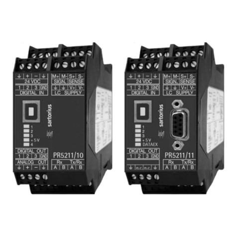
Sartorius PR 5210 Series User manual

Sartorius Hamburg GmbH , Meiendorfer Str. 205, D 22145 Hamburg, Germany
Tel: +49.40.67960.303 Fax: +49.40.67960.383
PR 5210 Transmitter Series
PR 5210/00 Profibus Transmitter
PR 5210/10 Digital Process Transmitter
PR 5210/11 Profibus Transmitter (without Analog Output)
Operating Manual
Operating manual 9499 050 52104 Edition 4 02.11.2006
for PR 5210 Release: 4.00

Please note
Any information in this document is subject t o change without not ice and does not represent a
commitment on the part of SARTORIUS. This product should be operated only by trained and qualif ied
personnel. In correspondence concerning t his product the type, name and release number as well as all
license numbers in relation t o t he product have to be quoted.
Important
This product is partly copyrighted. It may not be modified or copied and may not be used without
purchasing or writ t en authority f rom the copyright owner (SARTORIUS). By using this product , you
agree to be bound by the t erms stated herein.
Bitte beachten
Alle Angaben in diesem Dokument sind unverbindlich f ür SARTORIUS und stehen unter
Änderungsvorbehalt. Die Bedienung des Produktes darf nur von geschultem, fach- und sachkundigem
Personal durchgeführt werden. Bei Schriftwechsel über dieses Produkt bitte Typ, Bezeichnung und
Versionsnummer sowie alle mit dem Produkt in Zusammenhang stehenden Lizenznummern angeben.
Wichtig
Dieses Produkt ist in Teilen urheberrechtlich geschüt zt. Es darf nicht verändert oder kopiert und ohne
Erwerb oder schriftliche Einwilligung des unheberrechtlichen Eigentümers (SARTORIUS) nicht benutzt
werden. Durch die Benut zung dieses Produktes werden obige Bestimmungen von Ihnen anerkannt.

PR 5210 Operating Manual Contents
Sartorius 3
Contents
1SAFETY HINTS, ELECTRICAL PROTECTION CLASS........................................................................ 7
1.1 APPLICATION OF THE INSTRUMENT .................................................................................................................. 7
1.2 INITIAL INSPECTION ......................................................................................................................................... 7
1.3 BEFORE COMMISSIONING ................................................................................................................................7
1.3.1 Installation ...............................................................................................................................................................7
1.3.2 Electrost at ically sensitive components...........................................................................................................7
1.3.3 Protective earth......................................................................................................................................................8
1.3.4 Supply voltage connection .................................................................................................................................8
1.3.5 Failure and excessive st ress................................................................................................................................8
1.3.6 Fuse.............................................................................................................................................................................8
1.4 REPAIR AND MAINTENANCE............................................................................................................................. 8
1.4.1 Soldering work........................................................................................................................................................8
1.4.2 Cleaning ....................................................................................................................................................................8
1.4.3 Disposal .....................................................................................................................................................................8
2PR 5210 TRANSMITTER SERIES....................................................................................................... 9
2.1 THE TRANSMITTER VERSIONS .......................................................................................................................... 9
2.1.1 PR 5210/00 Version ...............................................................................................................................................9
2.1.2 PR 5210/10 Version (without Profibus)..........................................................................................................9
2.1.3 PR 5210/11 Version (without Analog Output).............................................................................................9
2.2 TRANSMITTER SURVEY ...................................................................................................................................10
2.3 LABEL ON THE HOUSING ................................................................................................................................10
2.4 HOUSING.......................................................................................................................................................11
2.5 CONNECTIONS ...............................................................................................................................................12
2.5.1 Load cell connection .......................................................................................................................................... 12
2.5.2 RS 232 Int erface..................................................................................................................................................14
2.5.3 RS 422 Int erface..................................................................................................................................................14
2.5.4 Analog out put (PR 5210/00 and PR 5210/10 only) ................................................................................15
2.5.5 3 Opto input s.......................................................................................................................................................16
2.5.6 3 Opto output s....................................................................................................................................................16
2.5.7 Profibus (PR 5210/00 and PR 5210/11 only).............................................................................................16
3OPERATING ELEMENTS ...................................................................................................................17
3.1 STATUS LEDS................................................................................................................................................17
3.2 CAL SWITCH.................................................................................................................................................18
3.2.1 Fact ory settings...................................................................................................................................................18
4SETUP AND CONFIGURATION........................................................................................................19
4.1 GENERAL .......................................................................................................................................................19
4.2 INSTALLATION WINDOWS TOOL.....................................................................................................................19
4.3 LOAD AND STORE SETUP AND CONFIGURATION ..............................................................................................20
4.3.1 Data in t he PR5210 ............................................................................................................................................20
4.3.2 Archive data in the PC...................................................................................................................................... 20
4.4 PRINT DATA SET.............................................................................................................................................20
4.5 SELECT LANGUAGE.........................................................................................................................................21
4.6 STATUS LINE..................................................................................................................................................21
4.7 ADU .............................................................................................................................................................22
4.7.1 Weighing point calibration ............................................................................................................................. 22
4.7.2 Weighing point configurat ion........................................................................................................................ 24
4.8 PARAMETER...................................................................................................................................................26
4.8.1 Analog out put ......................................................................................................................................................26

Contents PR 5210 Operating Manual
4 Sartorius
4.8.2 Profibus Address................................................................................................................................................. 27
4.8.3 Bus size................................................................................................................................................................... 28
4.8.4 Communication................................................................................................................................................... 28
4.8.5 Baudrate ................................................................................................................................................................ 28
4.8.6 Access ..................................................................................................................................................................... 28
4.8.7 Out puts.................................................................................................................................................................. 28
4.8.8 Inputs...................................................................................................................................................................... 28
4.8.9 Limits....................................................................................................................................................................... 29
4.9 CALIBRATE .................................................................................................................................................... 30
4.9.1 Smart Calibration ............................................................................................................................................... 31
4.10 ANALOG OUTPUT ADAPTION ......................................................................................................................... 32
4.11 STATUS ......................................................................................................................................................... 33
4.11.1 Analog part weight st atus............................................................................................................................... 33
5SMA PROTOCOL................................................................................................................................34
5.1 GENERAL....................................................................................................................................................... 34
5.2 KEY TO SYMBOLS USED ................................................................................................................................34
5.3 SCALE COMMAND SET.................................................................................................................................. 35
5.3.1 Request Displayed Weight ............................................................................................................................... 35
5.3.2 Request High- Resolution Weight .................................................................................................................. 35
5.3.3 Request Displayed Weight after St ability................................................................................................... 35
5.3.4 Request Scale to Zero........................................................................................................................................ 35
5.3.5 Request Scale to Tare........................................................................................................................................ 36
5.3.6 Set Scale Tare Weight ....................................................................................................................................... 36
5.3.7 Return Tare Weight ............................................................................................................................................ 36
5.3.8 Clear Scale Tare Weight .................................................................................................................................... 36
5.3.9 Invoke Scale Diagnostics.................................................................................................................................. 36
5.3.10 About Scale First Line........................................................................................................................................ 36
5.3.11 About Scale Scroll .............................................................................................................................................. 36
5.3.12 Scale Inf ormation ............................................................................................................................................... 37
5.3.13 Scale Inf ormat ion Scroll................................................................................................................................... 37
5.3.14 Abort Command.................................................................................................................................................. 37
5.3.15 Repeat Displayed Weight Cont inuously...................................................................................................... 37
5.4 SCALE RESPONSE MESSAGES........................................................................................................................ 38
5.4.1 Standard Scale Response Message................................................................................................................ 38
5.4.2 Unrecognized Command Response .............................................................................................................. 39
5.4.3 Communication Error Response .................................................................................................................... 39
5.4.4 Diagnostics Command Response................................................................................................................... 39
5.4.5 About ‘A’ and ‘B’ Command Response......................................................................................................... 39
5.4.6 Scale Inf ormat ion ‘I’ and ‘N’ Command Response................................................................................... 40
5.5 COMMUNICATION ERROR HANDLING............................................................................................................ 41
6PROFIBUS INTERFACE......................................................................................................................42
6.1 PROFIBUS INTERFACE PROTOCOL ................................................................................................................... 42
6.1.1 Write window (Input area).............................................................................................................................. 43
6.1.2 Read window (Output area)............................................................................................................................ 43
6.1.3 Data reading and writing................................................................................................................................. 43
6.1.4 Description of I/O area (read/ write window) ........................................................................................... 44
6.1.5 Register read and writ e via Profibus............................................................................................................ 46
6.1.6 Parameter read and write via Profibus....................................................................................................... 49
6.2 PROFIBUS REGISTER...................................................................................................................................... 51
6.2.1 Regist er 0: IO- St at us bit s f or reading ......................................................................................................... 51
6.2.2 Register 1: Scale stat us..................................................................................................................................... 51
6.2.3 Register 2: Status of state cont rolled action bit s.................................................................................... 52
6.2.4 Register 3: Status of t ransit ion controlled action bit s.......................................................................... 52
6.2.5 Register 4: Calibration inf ormation, error byt e........................................................................................ 53
6.2.6 Register 5: Transmitter type and version.................................................................................................... 54

PR 5210 Operating Manual Contents
Sartorius 5
6.2.7 Register 6: Board number ................................................................................................................................ 54
6.2.8 Register 7: (Reserved) ........................................................................................................................................ 54
6.2.9 Register 8 ...14: Weight data...........................................................................................................................54
6.2.10 Register 20 and 21: Parameter channel (read/writ e) ..............................................................................54
6.2.11 Register 22 ... 27: Limit values (read/write) ............................................................................................... 55
6.2.12 Register 30: Analog output (read/write)..................................................................................................... 55
6.2.13 Register 31: Fixtare (read/write)....................................................................................................................55
6.2.14 Register 80 ... 93: Act ion bits st ate controlled (writ e) ........................................................................... 55
6.2.15 Register 112 ... 125: Action bit s t ransit ion cont rolled (write).............................................................56
6.3 PROFIBUS PARAMETER NUMBERS .................................................................................................................57
6.3.1 Conf iguration parameter ................................................................................................................................. 57
6.3.2 Calibration............................................................................................................................................................. 60
6.3.3 ADU parameter ....................................................................................................................................................62
6.3.4 Parameter P99: Access code ...........................................................................................................................67
7TECHNICAL DATA .............................................................................................................................68
7.1 ANALOG PART, A/D CONVERSION .................................................................................................................68
7.1.1 Accuracy and stabilit y.......................................................................................................................................68
7.1.2 Sensit ivity .............................................................................................................................................................. 68
7.1.3 Load cells...............................................................................................................................................................68
7.2 RS 232 INTERFACE.......................................................................................................................................69
7.3 RS 422 INTERFACE.......................................................................................................................................69
7.4 ANALOG OUTPUT ...........................................................................................................................................69
7.5 DIGITAL INPUTS .............................................................................................................................................69
7.6 DIGITAL OUTPUTS ..........................................................................................................................................69
7.7 PROFIBUS DP ................................................................................................................................................69
7.8 POWER SUPPLY..............................................................................................................................................69
7.9 ENVIRONMENTAL EFFECTS .............................................................................................................................70
7.9.1 Environmental conditions................................................................................................................................70
7.9.2 Electromagnetic compatibilit y (EMC) .......................................................................................................... 70
7.9.3 RF int erf erence suppression ............................................................................................................................70
7.10 MECHANICAL DATA .......................................................................................................................................71
7.10.1 Construct ion type...............................................................................................................................................71
7.10.2 Dimensions............................................................................................................................................................ 71
7.10.3 Connections..........................................................................................................................................................71
7.10.4 Weight .................................................................................................................................................................... 71
7.11 ACCESSORIES ................................................................................................................................................71
7.12 OPTIONS........................................................................................................................................................71
8APPENDIX ...........................................................................................................................................72
8.1 EC DECLARATION OF CONFORMITY ...............................................................................................................72
8.2 EC TYPE-APPROVAL CERTIFICATE PTB D03-09-025..................................................................................75
8.3 SPARE PARTS.................................................................................................................................................76
8.4 EXAMPLE PRINT OUT CONFIGURATION AND CALIBRATION DATA / PARAMETERS .............................................76
8.5 GSD FILE FOR PROFIBUS DP .........................................................................................................................77
9INDEX ..................................................................................................................................................78


PR 5210 Operating Manual Safety Hints, Electrical Protection Class
Sartorius 7
1 SAFETY HINTS, ELECTRICAL PROTECTION CLASS
This inst rument was built and tested in accordance wit h t he safety regulations for
measuring and cont rol inst rumentation. The instrument was delivered in safe
condit ion. To maint ain this condition and t o ensure safe operation, t he operator
must f ollow t he hints and warnings given in t his document ation.
1.1 Application of the instrument
The inst rument is intended f or weighing inst allations and is particularly suitable f or tank and hopper
weighing and as a weight transmitter in intelligent cont rol systems. Product operation, commissioning
and maintenance must be done by well trained and qualified persons who know of the risks and avoid
them, or t ake measures to protect t hemselves.
The instrument is latest state of the art . No warrant y is taken that t he product is free of errors,
especially wit h reference t o t he software and hardware required for operation and supplied by third
parties. The manufacturer does not t ake any liability f or damage caused by incorrect use of t his
product . Using this product implies recognit ion of t he above- ment ioned regulat ions.
1.2 Initial inspection
Check t he cont ent s of the consignment for completeness and note whether any damage has occurred
during transport. If the cont ent is incomplete or damaged, a claim must be filed with the carrier
immediately and the Sartorius Hamburg sales or service organization must be inf ormed to permit repair
or replacement of the unit .
1.3 Before commissioning
Before commissioning, af t er storage and transport, t he instrument must be
inspected visually to preclude mechanical damage.
1.3.1 Installation
The instrument is designed for mounting on st andard rails (35 mm, acc. to DIN 46277).
When mount ing on the rail, ensure that between the modules to the left and right
of t he transmitter 20mm space is kept.
1.3.2 Electrostatically sensitive components
This inst rument contains electrostatically sensit ive components. Therefore, pot ential equalization must
be provided when working at the instrument (ant istatic protection).

Safety Hints, Electrical Protection Class PR 5210 Operating Manual
8 Sartorius
1.3.3 Protective earth
The connection to protective earth is done via t he mount ing rail.
1.3.4 Supply voltage connection
The supply volt age is 24V DC +10% / - 15%.
The power consumpt ion is 8.2 W maximum.
For connection t o 230 / 115 VAC an external power supply
(e.g. PR 1624/00) is required.
1.3.5 Failure and excessive stress
If the instrument is suspected of being unsafe, shut it down and protect it against accidental
operation. This is the case when the unit:
• is physically damaged,
• does not f unct ion any more,
• is stressed beyond the tolerable limit s (e.g. during storage, transport ).
1.3.6 Fuse
The inst rument has got no fuse to be exchanged. The load cell supply is protected against short circuit
by multif use elements. If the load cell supply switches of f , disconnect the device from power. Search f or
the reason and eliminate it. Aft er a cooling down period of about 3 minutes the power can be swit ched
on again.
1.4 Repair and maintenance
Repairs are subject to checking and can be carried out only at Sart orius Hamburg GmbH, Hamburg. In
case of def ect or f unct ional t rouble, please, cont act your local Sart orius organizat ion f or repair. When
returning the instrument for repair, an exact and complete f ault descript ion must be supplied.
Maintenance work may be carried out only by a trained technician aware of t he involved hazards,
whereby t he relevant precautions must be taken.
1.4.1 Soldering work
Carrying out any soldering work on t he unit is not allowed, excepting t he solder link (see chapter 2.5.1.4
and 2.5.1.5).
1.4.2 Cleaning
If necessary, the front panel can be cleaned using a damp, soft clot h. Use only little water or isopropyl
alcohol for moisturizing.
1.4.3 Disposal
Electronics scrap is special waste.
Please, f ollow your local disposal regulat ions.

PR 5210 Operating Manual PR 5210 Transmitter Series
Sartorius 9
2 PR 5210 TRANSMITTER SERIES
2.1 The Transmitter Versions
The t ransmit t ers of series 5210 are available in 3 models, a later extension t o a different model is not
possible. The respective version is clearly defined by the t ype number. The front f oils are adapted t o t he
version.
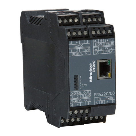
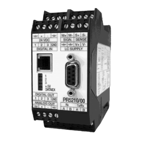
PR 5210/00 PR 5210/10 PR 5210/11
2.1.1 PR 5210/00 Version
This version is the fully equipped model, containing Profibus and Analog Output.
2.1.2 PR 5210/10 Version (without Profibus)
This version has got an Analog Output , but no Profibus connection, the respective menus in t he
operating tools are adapted to it .
2.1.3 PR 5210/11 Version (without Analog Output)
This version has got a Profibus connection, but no Analog Output, t he respective menus in the
operating tools are adapted to it .

PR 5210 Transmitter Series PR 5210 Operating Manual
10 Sartorius
2.2 Transmitter survey
• EC Type approval f or NAWI: PTB D03- 09- 025
• Accuracy 6000 e @ 6 samples/sec
• Internal resolut ion 4.8 Mio counts
• Linearit y < 0.002% (t yp.)
• Sample rate selectable: 6 ... 100/sec
• Digit al f ilter with selectable charact eristic
• Interfaces are galvanically isolated
• 3 pairs of programmable limit s
• 24 VDC Supply voltage
• Connect ions are made by 7 plug- in t erminal blocks, except Prof ibus
and RS 232 (RJ- 12) connect or
• The unit is suit able f or snap- in mount ing (rail)
• 5 st atus LEDs for power, communicat ion, error detection
Calibration and configurat ion of t he instrument are menu- guided via
PC or via Profibus commands.
• Calibration by means of weights or by entry of t he mV/V values
without addit ional calculations
• Analog Output 0/4 ... 20 mA, configurable for gross / net
(PR 5210/00 and PR 5210/10 only)
• Analog Output value defined by Profibus (PR 5210/00 only)
• Digit al Input 3 channels, galvanically isolated
• Digit al Out put 3 channels, galvanically isolated
Communicat ion protocols:
• RS 232 f or PC
• RS RS 422 for remote display
• Profibus- DP (PR 5210/00 and PR 5210/11 only)
2.3 Label on the housing
The wiring principle is located at t he side of the housing:
Other manuals for PR 5210 Series
1
This manual suits for next models
3
Other Sartorius Transmitter manuals
Popular Transmitter manuals by other brands

Zamel
Zamel exta life RNK-22 manual

Linear
Linear Multi-Code 4120 installation instructions

ABB
ABB AW400 Series instruction manual

Emerson
Emerson Rosemount Analytical HART 5081-A-HT instruction manual

Omega
Omega CDTX-90 Series user guide

Dwyer Instruments
Dwyer Instruments GSTC Series Installation and operating instruction manual