CYP CH-U331TX User manual

CH-U331TX
HDMI/VGA over IP Transmitter
with USB/KVM Extension
Operation Manual
Operation Manual

DISCLAIMERS
The information in this manual has been carefully checked and
is believed to be accurate. Cypress Technology assumes no
responsibility for any infringements of patents or other rights of third
parties which may result from its use.
Cypress Technology assumes no responsibility for any inaccuracies
that may be contained in this document. Cypress also makes no
commitment to update or to keep current the information contained
in this document.
Cypress Technology reserves the right to make improvements to this
document and/or product at any time and without notice.
COPYRIGHT NOTICE
No part of this document may be reproduced, transmitted,
transcribed, stored in a retrieval system, or any of its part translated
into any language or computer le, in any form or by any means—
electronic, mechanical, magnetic, optical, chemical, manual, or
otherwise—without express written permission and consent from
Cypress Technology.
© Copyright 2017 by Cypress Technology.
All Rights Reserved.
TRADEMARK ACKNOWLEDGMENTS
All products or service names mentioned in this document may be
trademarks of the companies with which they are associated.

SAFETY PRECAUTIONS
Please read all instructions before attempting to unpack, install or
operate this equipment and before connecting the power supply.
Please keep the following in mind as you unpack and install this
equipment:
• Always follow basic safety precautions to reduce the risk of re,
electrical shock and injury to persons.
• To prevent re or shock hazard, do not expose the unit to rain,
moisture or install this product near water.
• Never spill liquid of any kind on or into this product.
• Never push an object of any kind into this product through any
openings or empty slots in the unit, as you may damage parts
inside the unit.
• Do not attach the power supply cabling to building surfaces.
• Use only the supplied power supply unit (PSU). Do not use the PSU
if it is damaged.
• Do not allow anything to rest on the power cabling or allow any
weight to be placed upon it or any person walk on it.
• To protect the unit from overheating, do not block any vents or
openings in the unit housing that provide ventilation and allow for
sufcient space for air to circulate around the unit.
REVISION HISTORY
VERSION NO. DATE SUMMARY OF CHANGE
RDV1 23/02/17 Preliminary release
RDV2 20/04/17 Changed text/silkscreen
RDV3 29/08/17 Added video wall functions
VS1 12/09/17 Updated text/diagrams
VS2 01/11/17 Final technical review
VS3 11/01/18 Minor changes to the commands
VS4 05/06/18 Updated section 8.3
VS5 10/07/18 Added ISP SEL switch description

CONTENTS
1. Introduction......................................................1
2. Applications.....................................................1
3. Package Contents ..........................................2
4. System Requirements......................................2
5. Features............................................................3
6. Operation Controls and Functions.................4
6.1 Transmitter's Front Panel ........................... 4
6.2 Transmitter's Rear Panel............................ 6
6.3 IR Cable Pin Assignments ......................... 7
6.4 RS-232 Protocol.......................................... 7
6.5 Telnet Commands..................................... 8
6.6 WebGUI Control ...................................... 20
6.6.1 System Tab...................................... 21
6.6.2 Video Wall Tab ............................... 24
6.6.3 Network Tab ................................... 28
6.6.4 Functions Tab ................................. 30
7. Connection Diagram ....................................34
8. Specications ................................................35
8.1 Technical Specications ........................ 35
8.2 Video Specications............................... 36
8.3 Audio Specications............................... 37
9. Acronyms .......................................................39

1
1. INTRODUCTION
This unit is part of a 4K UHD Multi-Function Extension system that allows
you to extend HDMI or VGA signals along with KVM using the TCP/
IP protocol over regular Cat.5e/6/7 network cable. This extender
supports the transmission of Ultra High-Denition signals (up to 4K@30Hz
YUV 4:4:4 or 4K@60Hz YUV 4:2:0) with audio and USB up to 100m on a
single cable. The transmission distance can be further extended (up
to 100m per segment) by using gigabit network switches, allowing the
user to cascade the system without signal loss or introducing delay.
It is also possible to have the extension system's Transmitter operate
in multicast mode, allowing you to send a single AV signal to a large
number of Receivers within the same local network. Additionally, that
same multicast signal can be used to create large multi-display video
walls with amazing simplicity. This system is perfect for both residential
and commercial installation environments.
This system also features bi-directional IR and RS-232 pass-through,
analog line level in/out, and a microphone input (on the Receiver),
providing the user with a variety of audio options. The USB functionality
allows the system to act like a remote USB hub which, when combined
with the VGA input/output feature, provides a exible remote KVM
platform. Conguration information is provided via On Screen Display
(OSD) and control is by WebGUI, Telnet, and front panel controls.
2. APPLICATIONS
• HDMI, VGA, USB, Audio, IR, and RS-232 extension
• Broadcasting a system over a single Cat.5e/6 cable
• Multimedia display on a large number of displays via multicast
• Hotel or convention center display multi-monitor broadcast
• Long distance data and video transmission via cascading
• Distributed video matrix system
• Distributed video wall system
• Remote KVM control of a system

2
3. PACKAGE CONTENTS
• 1×HDMI/VGA over IP Transmitter with USB/KVM Extension
• 1×IR Extender Cable
• 1×IR Blaster Cable
• 1×5V/2.6A DC Power Adaptor
• 1×Operation Manual
4. SYSTEM REQUIREMENTS
• HDMI or VGA source equipment such as media players, video
game consoles, PCs or set-top boxes.
• HDMI or VGA receiving equipment such as HDTVs, monitors or audio
ampliers.
• Analog audio receiving equipment such as headphones, audio
ampliers or powered speakers.
• A Gigabit Ethernet network switch with jumbo frame support is
required. (8K jumbo frames are strongly recommended.)
• A Gigabit Ethernet switch with “IGMP snooping” enabled is required
for multicast support.

3
5. FEATURES
• HDMI 2.0 and DVI 1.0 compliant
• HDCP 1.4 & 2.2 compliant
• 1×HDMI input, 1×VGA input & 1×VGA bypass output
• Video, audio and control transmission over TCP/IP in Unicast (point-
to-point) or Multicast (single-to-many) modes
• Multi-monitor video wall support with 90° rotation
• HDMI input resolutions up to 4K@60Hz (YUV 4:2:0, 8-bit) or 4K@30Hz
(YUV 4:4:4, 8-bit)
Note: 4K@50/60Hz (YUV 4:2:0) sources are automatically converted to
4K@25/30Hz (RGB) for output
• VGA input and output resolutions up to WUXGA (RB)
• Supports pass-through of audio formats including LPCM 2.0/5.1/7.1,
and Bitstream over HDMI
Note: The optical output on Receivers can only support LPCM 2.0 &
Bitstream sources.
• The analog Line In on the Transmitter sends audio directly to the
analog Line Out and is inserted into the HDMI output on connected
Receivers
• The Mic In on the Receiver sends audio directly to the analog Line
Out on the Transmitter
• Both Tx and Rx may powered directly by PoE when connected to a
Gigabit Ethernet switch that provides PoE (802.3af)
• Supports USB keyboard, mouse and storage extension
• Supports IR and RS-232 bypass
• Unit can be controlled via WebGUI, Telnet, and front panel controls

4
6. OPERATION CONTROLS AND FUNCTIONS
6.1 Transmitter's Front Panel
POWER
RS-232
ISP
SEL
IR
OUT
RESET
IR LINK
LOOPBACK
Anti-DITHER
MODE ISP
VGA
LOOPBACK
LINK
IR
IN
21 3 4 5 6 7 8 9 1011 12
1POWER LED: This LED will ash while the unit is powering on and will
illuminate solidly once it is ready to be used.
2LINK LED: If the Transmitter has no network connection the LINK LED
will not illuminate. While the Transmitter is attempting to establish
a connection with a Receiver the LINK LED will ash. When the
Transmitter has established a stable connection with a Receiver
the LINK LED will illuminate solidly.
3RS-232 IN: Connect directly to your PC/laptop to send commands
to RS-232 devices connected to the Receiver. The baud rate is
congurable, but the default baud rate is 115200.
Note: When the Transmitter is in multicast mode every connected
Receiver unit can send RS-232 commands to the Transmitter
and commands sent from the Transmitter side will be sent to all
associated Receivers.
4ISP SEL: For Factory use only. By default this is set to the right (away
from the RS-232 port) and allows normal RS-232 functionality.
Setting this switch to the left enables ISP engineering mode.
5IR OUT: Connect to the provided IR Blaster to transmit IR signals sent
from the associated Receiver to devices within direct line-of-sight
of the IR Blaster.
6IR IN: Connect to the provided IR Extender to extend the IR control
range of remotely located devices. Ensure that the remote being
used is within direct line-of-sight of the IR Extender.
Note: When the Transmitter is in multicast mode the IR signal is sent
to all associated Receivers.
7IR WINDOW: Accepts IR signals from any standard remote control
and sends the signal to the IR Out on the associated Receiver.

5
Note: When the Transmitter is in multicast mode the IR signal is sent
to all associated Receivers.
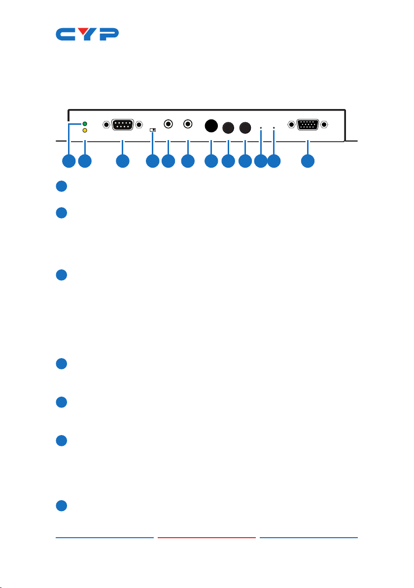
8LOOPBACK/LINK: This button controls multiple functions:
aLoopback: Press this button momentarily to toggle the VGA
Loopback function on and off, allowing you to locally monitor non-
HDCP HDMI sources (1080p or below) for troubleshooting purposes.
bVideo Link: Press and hold the button for 3 seconds to enable or
disable the Video Link. When the link is disabled and the Receiver
is connected to a display it will show the system’s current IP and
rmware information.
cReset to Factory Defaults: Press and hold this button when
powering the unit on until both the POWER and LINK lights are
blinking. Once both lights are blinking you can reboot the unit
and all settings will be returned to the factory defaults (Including
resetting the IP mode to auto, broadcast channel to 0, and the
streaming mode to multicast). A new IP address will be assigned
automatically within the 169.254.xxx.xxx address range.
9MODE/Anti-DITHER: This button controls multiple functions:
aVideo Mode: Press this button momentarily to toggle the video
data streaming method between “Graphic” and “Video” modes.
“Graphic” mode is optimized for high-detail static displays and
“Video” mode is optimized for full motion video.
bAnti-Dither: Press and hold this button for 3 seconds to enable
and switch between the three “Anti-Dither” modes (1-bit, 2-bit
and off). Certain graphics cards use dithering to emulate a larger
color palette, but dithering causes difculty for maintaining low-
bandwidth during real-time video compression, so these Anti-
Dithering modes are designed to remove the dithering prior to
compression and transmission of the signal. If the source is not
using dithering, please leave this feature disabled as it may cause
a blocking effect with non-dithered content.
Note: This feature is set to “off” by default.
10 ISP: For factory use only.
11 RESET: Press this recessed button to reboot the unit (Settings will not
be reset).
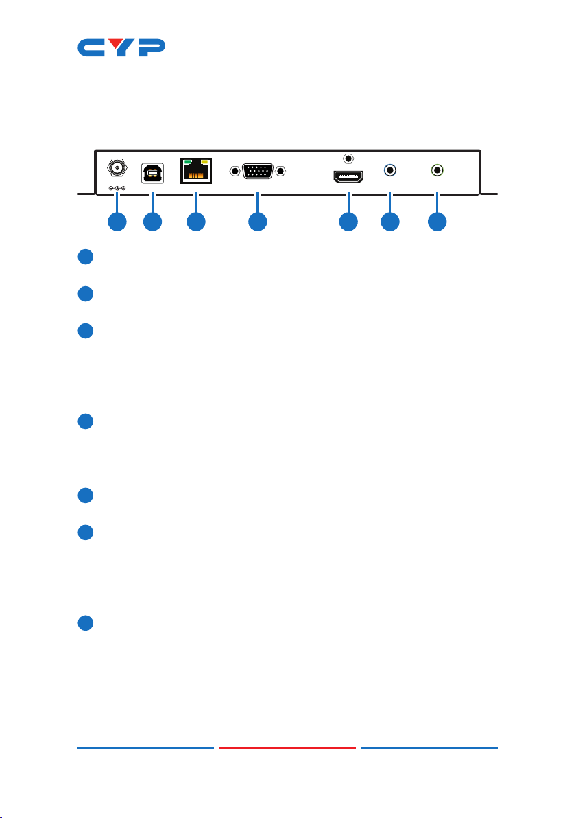
12 VGA LOOPBACK OUT: Connect to an analog VGA monitor to
locally view the connected VGA or HDMI (non-HDCP, 1080p or

6
lower) source.
6.2 Transmitter's Rear Panel
DC 5V
USB VGA IN HDMI IN LINE IN LINE OUT
LAN (PoE)
2 3 4 5 6 7
1
1DC 5V: Plug the 5V DC power adapter into the unit and connect it
to an AC wall outlet for power. (Optional if powered by PoE)
2USB: Connect directly to a PC to extend its USB functionality to the
ports on the connected Receiver.
3LAN (PoE): Connect via a Gigabit Ethernet switch to compatible
Receiver(s) to transmit data, and to a PC/laptop to control the unit
via WebGUI.
Note: This unit can be powered directly by the connected Gigabit
Ethernet switch if it provides PoE (802.3af).
4VGA IN: Connect to VGA source equipment such as a PC or
laptop.
Note:PCtextandcontentwithnedetailsmaydisplaywithsome
visual artifacts when transmitted at 4K@60Hz (YUV 4:2:0).
5HDMI IN: Connect to HDMI source equipment such as a media
player, game console or set-top box.
6LINE IN: Connect to the stereo analog output of a device such as
a CD player or PC.
Note: When a live audio source is connected to the Line In, it will
be automatically embedded into the transmitted signal, and will
completely replace any existing HDMI audio.
7LINE OUT: Connect to powered speakers or an amplier for stereo
analog audio output. This will output the audio from the Mic In on
the connected Receiver.
Note: This function is only available in Unicast mode. The Mic In
audio channel from the Receiver is only active when an analog
source is also connected to the Line In port on the Transmitter.

7
6.3 IR Cable Pin Assignments
3
1
2
IR Signal
Power
Ground
IR Extender
3
1
2
IR Blaster
Power
IR Signal
NC
6.4 RS-232 Protocol
TRANSMITTER
►
◄
RECEIVER
Pin Denition Pin Denition
1 NC 1 NC
2Tx 2Rx
3Rx 3Tx
4 NC 4 NC
5 GND 5 GND
6 NC 6 NC
7 NC 7 NC
8 NC 8 NC
9 NC 9 NC

8
6.5 Telnet Commands
1. Help
COMMAND DESCRIPTION AND PARAMETERS
HELP Show the full command list.
HELP N1 Show help details about command
N1.
N1 = {Any command name}
2. Network
COMMAND DESCRIPTION AND PARAMETERS
GET_IPCONFIG Show the current IP conguration.
SET_IP_MODE N1 Set the IP conguration mode.
Available values for N1:
0 [Static IP Mode]
1 [DHCP Mode]
2 [Auto IP Mode]
GET_IP_MODE Show the current IP conguration
mode.
SET_IP_ADDRESS N1 Set the static IP address.
N1 = X.X.X.X [X = 0~255]
GET_IP_ADDRESS Show the current IP address.
SET_NETMASK N1 Set the Ethernet netmask.
N1 = X.X.X.X [X = 0~255]
GET_NETMASK Show the current Ethernet netmask.
SET_GATEWAY N1 Set the IP gateway address.
N1 = X.X.X.X [X = 0~255]
GET_GATEWAY Show the current gateway address.
SET_NET_MODE N1 Set the network broadcast mode.
Available values for N1:
0 [Unicast Mode]
1 [Multicast Mode]
GET_NET_MODE Show the current network broadcast
mode.

9
2. Network
COMMAND DESCRIPTION AND PARAMETERS
SET_JUMBO_MTU N1 Enable/disable the jumbo frame MTU.
Available values for N1:
0 [Disabled]
1 [Enabled]
GET_JUMBO_MTU Show the jumbo frame MTU state.
3. System
COMMAND DESCRIPTION AND PARAMETERS
GET_HARDWARE_VERSION Show the current hardware version.
FACTORY_RESET N1 Perform a factory reset on the unit
and select the IP mode after the
reset completes.
Available values for N1:
0 [Reset into Static IP
mode]
1 [Reset into Auto IP
mode]
REBOOT Reboot the unit.
4. Transmitter Specic
COMMAND DESCRIPTION AND PARAMETERS
SET_TX_CHANNEL N1 Set the VoIP transmission channel.
N1 = 0~255
GET_TX_CHANNEL Show the current VoIP transmission
channel.
SET_PQ_MODE N1 Set the Tx video optimization mode.
Available values for N1:
0 [Graphic optimized
mode]
1 [Video optimized
mode]
GET_PQ_MODE Show the current Tx video
optimization mode.

10
4. Transmitter Specic
COMMAND DESCRIPTION AND PARAMETERS
SET_HDCP_ALLOW N1 Enable/disable HDCP encrypted
source support.
Available values for N1:
0 [Disabled]
1 [Enabled]
GET_HDCP Show the current HDCP support state.
SET_USB_MOUSE N1 Set the USB mouse performance
mode.
Available values for N1:
0 [High resolution mode]
1 [Compatibility mode]
GET_USB_MOUSE Show the current USB mouse
performance mode.
SET_BANDWIDTH N1 Set the broadcast stream bandwidth
maximum.
Available values for N1:
0 [50 Mbps]
1 [100 Mbps]
2 [200 Mbps]
3 [400 Mbps]
4 [Best Effort]
SET_FRAME_RATE N1 Set the percentage of frames from
the source video to encode.
N1 = 2~100 [Frame Percent]
SET_VW_OSD N1 {N2} Enable/disable video wall OSD to
display the Target Receiver number
on the designated display.
Available values for N1:
0 [Disable]
1 [Enable]
N2 = 0~255 [Target Rx {Optional}]

11
4. Transmitter Specic
COMMAND DESCRIPTION AND PARAMETERS
Note: Target Receiver number can
be obtained by turning on the Video
Wall OSD. Omitting N2 makes the
setting global to all Receivers.
SET_VW_LAYOUT N1 N2 {N3} Set the video wall’s total horizontal
and vertical display count.
N1 = 1~16 [Horizontal display
count]
N2 = 1~16 [Vertical display
count]
N3 = 0~255 [Target Rx {Optional}]
Note: Target Receiver number can
be obtained by turning on the Video
Wall OSD. Omitting N3 makes the
settings global to all Receivers.
SET_VW_POS N1 N2 {N3} Set the display’s position within the
video wall. (Cannot exceed the
video wall’s horizontal and vertical
display count.)
N1 = 0~15 [Row]
N2 = 0~15 [Column]
N3 = 0~255 [Target Rx {Optional}]
Note: Target Receiver number can
be obtained by turning on the Video
Wall OSD. Omitting N3 makes the
settings global to all Receivers.

12
4. Transmitter Specic
COMMAND DESCRIPTION AND PARAMETERS
SET_VW_BC N1 N2 N3 N4 {N5} Set the video wall display’s bezel
compensation values.
N1 = 0~99999 [Video width]
N2 = 0~99999 [Total display width]
N3 = 0~99999 [Video height]
N4 = 0~99999 [Total display height]
N5 = 0~255 [Target Rx {Optional}]
Note: Target Receiver number can
be obtained by turning on the Video
Wall OSD. Omitting N5 makes the
settings global to all Receivers.
SET_VW_HSCALE N1 {N2} Set the video wall display’s horizontal
zoom amount.
N1 = 0~99999 [Zoom amount in 1
pixel units]
N2 = 0~255 [Target Rx {Optional}]
Note: Target Receiver number can
be obtained by turning on the Video
Wall OSD. Omitting N2 makes the
setting global to all Receivers.
SET_VW_VSCALE N1 {N2} Set the video wall display’s vertical
zoom amount.
N1 = 0~99999 [Zoom amount in 1
pixel units]
N2 = 0~255 [Target Rx {Optional}]
Note: Target Receiver number can
be obtained by turning on the Video
Wall OSD. Omitting N2 makes the
setting global to all Receivers.

13
4. Transmitter Specic
COMMAND DESCRIPTION AND PARAMETERS
SET_VW_SHIFT N1 N2 {N3} Set the video wall display’s output
shift.
Available values for N1:
U [Shift up]
D [Shift down]
L [Shift left]
R [Shift right]
N2 = 0~80000 [Pixel shift amount.
Must be in increments
of 8.]
N3 = 0~255 [Target Rx {Optional}]
Note: Target Receiver number can
be obtained by turning on the Video
Wall OSD. Omitting N3 makes the
setting global to all Receivers.
SET_VW_DELAY N1 {N2} Set the video wall display delay.
N1 = 0~99999 [Delay in
microseconds]
N2 = 0~255 [Target Rx {Optional}]
Note: Target Receiver number can
be obtained by turning on the Video
Wall OSD. Omitting N2 makes the
setting global to all Receivers.
5. Receiver Specic
COMMAND DESCRIPTION AND PARAMETERS
SET_EDID_COPY N1 Copy and use the EDID of the
connected display.
Available values of N1:
0 [Disabled]
1 [Enabled]
GET_EDID_COPY Show the state of the EDID copy
function.

14
5. Receiver Specic
COMMAND DESCRIPTION AND PARAMETERS
R N1 Select the VoIP transmission channel
to display.
N1 = 0~255
GET_RX_CHANNEL Show the currently selected VoIP
transmission channel.
SET_OUTPUT_RES N1 Set the output resolution.
Available values for N1:
0 [640×480@60Hz]
2 [800×600@60Hz]
4 [1024×768@60Hz]
6 [1280×768@60Hz]
7 [1280×800@60Hz]
8 [1280×1024@60Hz]
10 [1360×768@60Hz]
11 [1366×768@60Hz]
12 [1440×900@60Hz]
14 [1400×1050@60Hz]
15 [1600×900@60Hz]
16 [1600×1200@60Hz]
17 [1680×1050@60Hz)
20 [1920×1200@60Hz)
22 [Bypass]
23 [Auto-Detect]
24 [480i@60Hz]
25 [576i@50Hz]
26 [480p@60Hz]
28 [576p@50Hz]
29 [720p@60Hz]
31 [720p@50Hz]
32 [720p@30Hz]
34 [720p@25Hz]
35 [1080i@60Hz]
37 [1080i@50Hz]
38 [1080p@60Hz]
40 [1080p@50Hz]
41 [1080p@30Hz]

15
5. Receiver Specic
COMMAND DESCRIPTION AND PARAMETERS
SET_OUTPUT_RES N1 43 [1080p@25Hz]
44 [1080p@24Hz]
Note: Downscaling is limited to 1/2
of the horizontal/vertical pixels of
the source. For example: 3840×2160
(4K) to 1920×1080 (1080p) is OK, but
3840×2160 (4K) to 1280×720 (720p) or
640×480 is not. When outputting to a
video wall, the resolution of the entire
video wall together (rather than
each individual display) should be
used for this calculation.
SET_VW N1 Enable/disable video wall
functionality.
Available values for N1:
0 [Disable]
1 [Enable]
GET_VW Show video wall functionality status.
SET_VW_OSD N1 Enable/disable video wall OSD to
display the Target Receiver number
on the connected display.
Available values for N1:
0 [Disable]
1 [Enable]
GET_VW_OSD Show the current video wall OSD
state.
SET_VW_LAYOUT N1 N2 Set the video wall’s total horizontal
and vertical display count.
N1 = 1~16 [Horizontal display
count]
N2 = 1~16 [Vertical display
count]
GET_VW_LAYOUT Show the video wall’s total horizontal
and vertical display count.

16
5. Receiver Specic
COMMAND DESCRIPTION AND PARAMETERS
SET_VW_POS N1 N2 Set the position within the video wall
of the display connected to this
Receiver. (Cannot exceed the video
wall’s horizontal and vertical display
count.)
N1 = 0~15 [Row]
N2 = 0~15 [Column]
GET_VW_POS Show the position within the video
wall of the display connected to this
Receiver.
SET_VW_BC N1 N2 N3 N4 Set the video wall bezel
compensation values for the display
connected to this Receiver.
N1 = 0~99999 [Video width]
N2 = 0~99999 [Total display width]
N3 = 0~99999 [Video height]
N4 = 0~99999 [Total display height]
GET_VW_BC Show the video wall bezel
compensation values for the display
connected to this Receiver.
SET_VW_HSCALE N1 Set the horizontal zoom amount
of the display connected to this
receiver.
N1 = 0~99999 [Zoom amount in 1
pixel units]
GET_VW_HSCALE Show the horizontal zoom amount
of the display connected to this
receiver.
SET_VW_VSCALE N1 Set the vertical zoom amount of the
display connected to this receiver.
N1 = 0~99999 [Zoom amount in 1
pixel units]
Table of contents
Other CYP Transmitter manuals