SASFORKS QUICK COUPLER User manual

Made in USA
QUICK COUPLER
=======================================
OPERATOR MANUAL
======== MANUAL v3 =====

SAS/op/proc/forks/operator man/Quick Coupler /SAS Quick Coupler Manual v3.pub 9:52 AM 3/30/2021 © 2021 S.A.S. of Luxemburg, LLC PAGE 2
TABLE OF CONTENTS (PAGE 2)
SAS™ QUICK COUPLER
• Introduction Letter ............................................................................................. Page 3
• General Safety Guidelines................................................................................ Page 4 - 5
• CE Specific Notices & EMERGENCY STOP FUNCTION ............................... Page 5
• Serial Number location ..................................................................................... Page 6
• Installation ........................................................................................................ Page 7
• Optional electric pump kit wiring ...................................................................... Page 8
• Pre-Operation Inspection (& Maintenance)….................................................. Page 9 - 10
• Connecting / Disconnecting ............................................................................. Page 11
• Repair flow chart ….. ........................................................................................ Page 12
• Weld Notice ....................................................................................................... Page 13
• Limited warranty................................................................................................ Page 14
• Parts Guide:
Note-This manual may be printed with only one last page, matching interface
of unit shipped. Comprehensive manual will have all interface parts lists.
• Standard SAS-EURO-ISO Interface Quick Coupler F5551 & up... Page 15
• Standard SAS-EURO-ISO Interface Quick Coupler F5474 & down Page 16
• Custom JRB416 Interface Quick Coupler .................... Page 17
• Custom JRB418 Interface Quick Coupler .................... Page 18
• Custom JRB420 Interface Quick Coupler .................... Page 19
• Custom IT28 Interface Quick Coupler .................... Page 20
• Custom IT38 Interface Quick Coupler .................... Page 21
• Custom F6094 Interface Quick Coupler ..................... Page 22
LIMITED INTENDED USE OF THIS EQUIPMENT:
SAS QUICK COUPLER is an interface device that allows matching interface wheel loader attachments,
such as a bucket, forks, grapple, plow or other tool to connect and secure such tool to front of wheel
loader, when properly installed and used by the operator. The SAS QUICK COUPLER is not intended to
lift any people and is not intended to be used with any device or object for that purpose. The SAS QUICK
COUPLER is not intended to lift any object overhead of any people. This attachment is considered a
non-OEM attachment and has not been approved by any specific wheel loader manufacturer. Customer
is responsible to read the wheel loader’s manual and warranty documents, if any, and identify any impact
installation and use of this attachment may have on the wheel loader’s warranty. Read this manual com-
pletely before installation or use.

SAS/op/proc/forks/operator man/Quick Coupler /SAS Quick Coupler Manual v3.pub 9:52 AM 3/30/2021 © 2021 S.A.S. of Luxemburg, LLC PAGE 3
INTRODUCTION LETTER (PAGE 3)
SAFETY
Proprietary Rights: All designs and other proprietary rights provided by S.A.S. of Luxemburg, LLC. to
Buyer are to remain the property of S.A.S. of Luxemburg, LLC., and Buyer shall honor all proprietary
legends. Notice: The SAS FORKS™ attachment, this Operator Manual, www.sasforks.com web site,
pictures, content, designs, forks, and likeness of such, are property of S.A.S. of Luxemburg, LLC. and are
protected under all applicable Copyright, Trade Mark, Trade Dress, and Pending Patent. No information,
pictures, designs, or forks may be duplicated in part, entirety, or in likeness.
S.A.S. of Luxemburg, LLC, 133 Center Drive Hwy 54, PO Box 260, Luxemburg, WI 54217 USA
Phone: 920-845-2198 • 1-877-SAS-FORK • Fax: 920-845-2309 • Web: www.sasforks.com
TO THE OWNERS, MANAGERS, AND OPERATORS OF LOADERS
EQUIPPED WITH SAS™ FORKS ATTACHMENTS
Safety is the most important issue in the workplace. Observing safety guidelines, equipment
capacities and using common sense will provide a work environment that is safe and efficient
for employees, management and customers. It is important that you and your operators read
and understand the information included in this manual prior to use of this equipment.
Safety warnings are highlighted through out this manual. Understanding the significance of
these symbols is important. The following is a definition of each symbol you will encounter in
this manual:
Caution Symbol is intended to draw your attention to important safety
information, hazard or precaution.
Danger Symbol indicates a hazardous situation that if not avoided will re-
sult in serious injury or death.
Warning Symbol indicates a hazardous situation that if not avoided could
result in serious injury or death.
Caution Symbol indicates a hazardous situation that if not avoided
could result in minor injury or potential property damage.
The following information presented in this Operator Manual for SAS FORKS™ is intended to
be a guide only, and is not meant to encompass all issues that may need to be addressed for
your particular type of business operation.
If you encounter any additional information that would be helpful to us, or others, please contact
us.
Thank you for your business,
SAS LLC Phone: Email:
S.A.S. OF LUXEMBURG, LLC. U.S.A. Phone: 1-920-845-2198 buyit@sasforks.com
133 Center Dr Hwy 54 · PO Box 260
LUXEMBURG, WI 54217 U.S.A.

SAS/op/proc/forks/operator man/Quick Coupler /SAS Quick Coupler Manual v3.pub 9:52 AM 3/30/2021 © 2021 S.A.S. of Luxemburg, LLC PAGE 4
GENERAL SAFETY GUIDELINES (PAGE 4)
S.A.S. of Luxemburg, LLC, 133 Center Drive Hwy 54, PO Box 260, Luxemburg, WI 54217 USA
Phone: 920-845-2198 • 1-877-SAS-FORK • Fax: 920-845-2309 • Web: www.sasforks.com
Operation of equipment should only be performed by qualified and trained individuals. All persons operating
or working in the area of operation should read this manual and a copy of this manual should be kept with
the equipment. To be considered qualified you must:
• Understand the written instructions supplied by the manufacturer of the device (within this manual),
the manufacturer of the wheel loader, all company rules and any applicable OSHA regulations.
• Completed training including actual operation, demonstrating competence and safe operation.
• Know and follow the safety rules and regulations of the jobsite.
Operation of equipment under the influence of illegal, prescribed or over the counter
drugs can result in potential injury or property damage. Consult your physician be-
Inspect the device and perform all preventative maintenance before operation at the
start of every shift. Failure to perform inspections or proper maintenance can result
in equipment failure resulting in serious injury or property damage.
Read operators manual and follow all safety procedures for the equipment this de-
vice is attached to. Failure to follow Manufacturers recommendations can result in
serious injury and property damage.
Do not exceed posted weight limits on equipment or loader. Exceeding rated load
limits will result in equipment damage, loss of steering control, serious injury or death.
This equipment is operated by high pressure hydraulics. Hydraulics are a stored power
source and as such must be treated as energized at all times. Be certain pressure has
been relieved prior to handling, inspecting or performing maintenance on this unit. Follow
lockout tag out procedures and release all stored energy before servicing equipment.
Failure to release energy or disable hydraulic energy can result in serious injury or death.
High pressure fluids can also discharge at great velocity. Be certain to wear safety glass-
es while inspecting, operating and maintaining equipment.
Not designed to be operated in an explosive environment. Only use this equipment
in well ventilated areas, a sufficient distance away from flammable or explosive gas-
es, liquids or other hazards to avoid risk of ignition. Operating this equipment in an
explosive environment may cause an explosion and fire resulting in injury, death, and
substantial property damage.
Operation of equipment by un-qualified or un-trained individuals can result in serious
injury or death. Verify all operators have received proper training on this equipment.
This device has numerous moving components. Do not wear loose fitting clothing,
rings, jewelry or other items that may become entangled in device. Be aware of re-
sulting pinch points and keep clear during operation, inspection and maintenance.
Pinch points exist between moving parts on the device, between device and vehicle,
device and wheel loader, failure to keep clear while in operation can result in serious
injury or death.

SAS/op/proc/forks/operator man/Quick Coupler /SAS Quick Coupler Manual v3.pub 9:52 AM 3/30/2021 © 2021 S.A.S. of Luxemburg, LLC PAGE 5
CE SPECIFIC NOTICES
EMERGENCY STOP FUNCTION
To immediately stop the motion of this equipment:
1. Operator is to release joystick button(s).
Additional secondary alternative measures to immediately stop the motion include:
2. Moving wheel loader’s auxiliary hydraulic 3rd spool lever to neutral position
3. And/or turning off the ignition key of the wheel loader to shut off the engine
All three emergency stop options above ultimately stop the flow of hydraulic fluid.
Notice: Even after emergency stop function is followed, there is residual stored
hydraulic pressure in the system. See following:
THIS EQUIPMENT IS OPERATED BY HIGH PRESSURE HYDRAULICS
Hydraulics are a stored power source and as such must be treated as energized at
all times. Be certain pressure has been relieved prior to handling, inspecting or per-
forming maintenance on this unit. Follow lockout tag out procedures and release all
stored energy before servicing equipment. Failure to release energy or disable hy-
draulic energy can result in serious injury or death. High pressure fluids can also
discharge at great velocity. Be certain to wear safety glasses while inspecting, oper-
ating and maintaining equipment.
STAY CLEAR
• Do not lift persons with this equipment.
• People should always stand a safe distance away from this equipment.
• Do not go near or under this equipment or any object lifted by this equipment.
ENERGY ISOLATION
Follow Refer to “DISCONNECTION” information within this manual and the ma-
chine’s OEM manual. Stored energy, such as gravity, hydraulics or other sources
pose a risk to anyone near or servicing this equipment. Be sure release and remove
all stored energy sources before servicing.
The symbol at the left indicates hydraulic hose coupling quick release self sealing. It
is recommended to be installed by the customer at the time this equipment is initially
attached to the wheel loader.
POWER FAILURE
In the event of electrical or hydraulic supply failure from the wheel loader occurs, the
equipment will stop further motion. Under normal circumstances the equipment is
not expected to drop a load. The symbol at the left indicates the hydraulic controls on
this equipment are normally closed. Thus without electrical power the gate valves
are closed, in essence halting further movement.
SOUND
This equipment does not emit more than 70dba.
VIBRATIONS
This equipment does not transfer vibrations in excess of 2.5m/s2.
OPERATING TEMPERATURE
This equipment is best suited to operate in temperatures between 30°F to 90°F
with minimum allowable temperature –25°F and maximum temperature 150°F
GENERAL SAFETY GUIDELINES (PAGE 5)
S.A.S. of Luxemburg, LLC, 133 Center Drive Hwy 54, PO Box 260, Luxemburg, WI 54217 USA
Phone: 920-845-2198 • 1-877-SAS-FORK • Fax: 920-845-2309 • Web: www.sasforks.com
Section not applicable to quick coupler.

SAS/op/proc/forks/operator man/Quick Coupler /SAS Quick Coupler Manual v3.pub 9:52 AM 3/30/2021 © 2021 S.A.S. of Luxemburg, LLC PAGE 6
SERIAL NUMBER (PAGE 6)
SAS™ QUICK COUPLER
Serial Number Location:
Stamped in steel on left side (as from driver seat of wheel loader), immediately above
the SAS FORKS welded logo plate
Serial Number Format:
SAS Fxxxx
S.A.S. of Luxemburg, LLC, 133 Center Drive Hwy 54, PO Box 260, Luxemburg, WI 54217 USA
Phone: 920-845-2198 • 1-877-SAS-FORK • Fax: 920-845-2309 • Web: www.sasforks.com

SAS/op/proc/forks/operator man/Quick Coupler /SAS Quick Coupler Manual v3.pub 9:52 AM 3/30/2021 © 2021 S.A.S. of Luxemburg, LLC PAGE 7
INSTALLATION (PAGE 7)
SAS™ QUICK COUPLER
STEP 1 - PREPARATION:
• Establish a safe work area. A flat surface clean work area without trip hazards.
• Park wheel loader on firm level ground.
Lower exiting attachment (ie: bucket) to rest on ground.
Set parking brake and turn engine off.
• Follow wheel loader manufacturer’s instructions to depressurize hydraulic system.
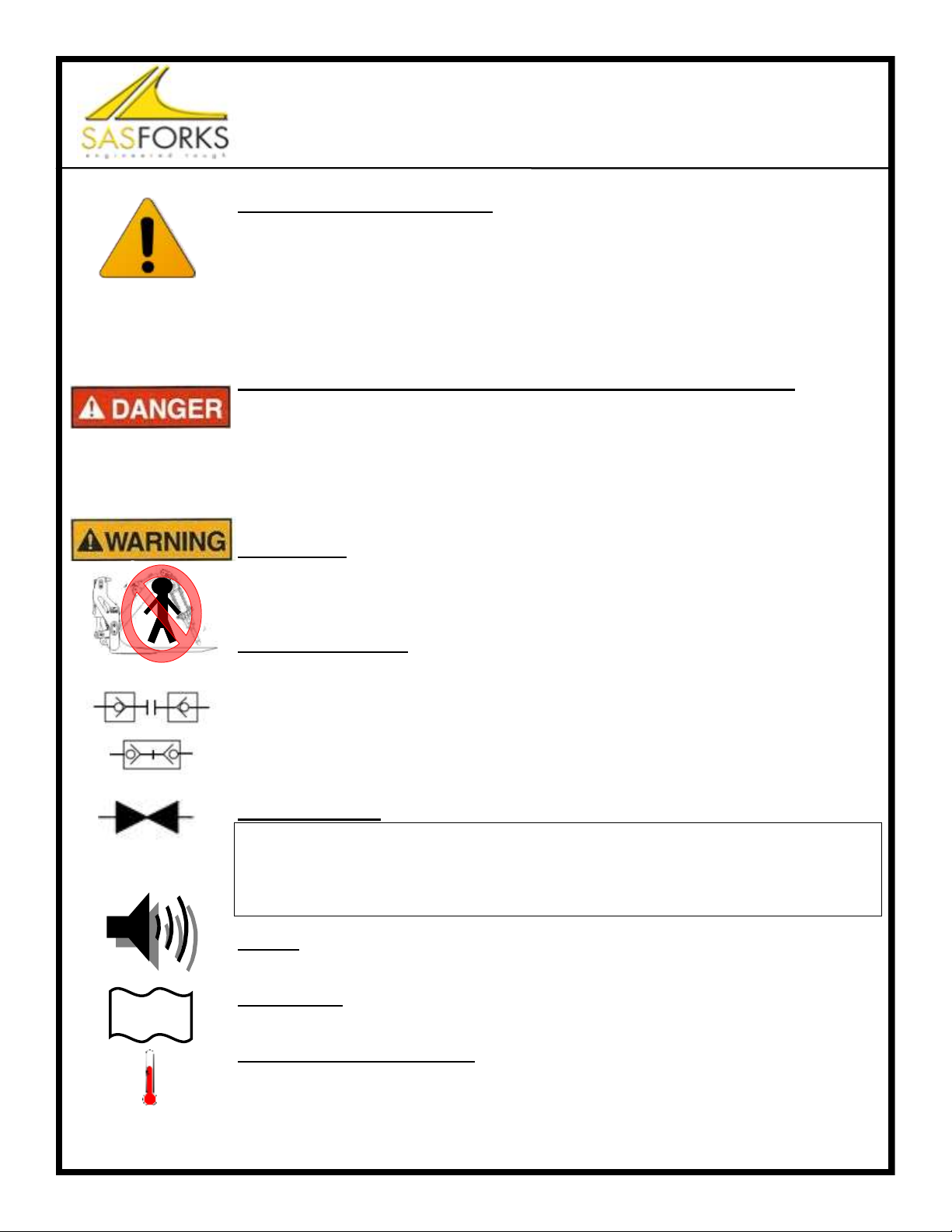
• Do not work under a lifted object, loader arms or Quick Coupler. Avoid pinch & crush hazards.
• Remove existing pinned on attachment.
• Inspect pins & bushings in machine arms, replace as necessary.
STEP 2 - INSTALLATION:
• Apply grease to pins, bushings and pin holes on Quick Coupler.
• Align pin holes, insert pins and secure pins properly.
• Grease all pin zerk points.
STEP 3 - HYDRAULIC CONNECTION:
• Option #1: Electric pump kit from SAS Forks (diagram on next page)
• Option #2: Bucket roll back hydraulics with solenoid valve/switch.
• Option #3: Use 3rd spool auxiliary hydraulics on loader.
• Reference matching parts page within this manual to determine
maximum psi. (either 3,500; 5,000; 6,000). Have hydraulic pressure set below maximum.
• Determine hose length to avoid creating tension in all positions.
• Avoid excessive length that hoses would hang down to ground.
• Install high pressure hydraulic hoses. Recommend hose psi. to exceed cylinder requirements.
STEP 4 - TEST ROLL FORWARD AND ROLL BACK:
• During this test of motion, ensure smooth lifting & tilting of Quick Coupler. Watch for undesirable
contact between wheel loader lift arms and Quick Coupler. Also watch for hose pinch points.
• Begin testing by moving control levers slowly:
A. With Quick Coupler near ground level, fully roll back.
B. With Quick Coupler lifted high, fully rotate to dump position.
• Contact SAS FORKS™ if you experience interference issues to discuss stop options.
STEP 5 - TEST CYLINDER AND LOCKING PIN ENGAGEMENT:
• Engage hydraulics to actuate cylinder within Quick Coupler to extend Locking Pins.
• Visually verify Locking Pins are extended fulling into the exterior pin holes on the Quick Coupler.
• A few cycles of extend and retract maybe required to remove air from lines.
STEP 6 - CHECK & FILL HYDRAULIC FLUID:
• After installation test, check wheel loader hydraulic fluid level and fill as needed.
S.A.S. of Luxemburg, LLC, 133 Center Drive Hwy 54, PO Box 260, Luxemburg, WI 54217 USA
Phone: 920-845-2198 • 1-877-SAS-FORK • Fax: 920-845-2309 • Web: www.sasforks.com
Installation of purchased attachment may void machine manufacturer warranty, if any.
►Installation of QUICK COUPLER on wheel loader requires interfacing with high
pressure hydraulic system. Installation should only be performed by qualified indi-
viduals, such as an experienced Heavy Equipment Service Technician. Failure to
follow these instructions and precautions in wheel loader manufacturer’s service
manual can result in serious damage to equipment and/or result in injury or death.
►Failure of hydraulic system or high pressure fluid leaks can result in serious injury
►Use caution while installing, testing & operating this unit. Be aware of and avoid:
-Pinch Points, -High Pressure hydraulic fluids or stored energy, -People in the area.

SAS/op/proc/forks/operator man/Quick Coupler /SAS Quick Coupler Manual v3.pub 9:52 AM 3/30/2021 © 2021 S.A.S. of Luxemburg, LLC PAGE 8
INSTALLATION (PAGE 8)
OPTIONAL: 24 VOLT PUMP KIT
S.A.S. of Luxemburg, LLC, 133 Center Drive Hwy 54, PO Box 260, Luxemburg, WI 54217 USA
Phone: 920-845-2198 • 1-877-SAS-FORK • Fax: 920-845-2309 • Web: www.sasforks.com
Volts Control Part Number
Standard: shown above 24 Pendent switch 0-MM-0-PMP KIT P 24V
Option 24 Lever on tank 0-MM-0-PMP KIT L 24V
Option 12 Pendent switch 0-MM-0-PMP KIT P 12V
Optional Pump Kits

SAS/op/proc/forks/operator man/Quick Coupler /SAS Quick Coupler Manual v3.pub 9:52 AM 3/30/2021 © 2021 S.A.S. of Luxemburg, LLC PAGE 9
DAILY PRE-OPERATION INSPECTION (PAGE 9)
GUIDELINES
S.A.S. of Luxemburg, LLC, 133 Center Drive Hwy 54, PO Box 260, Luxemburg, WI 54217 USA
Phone: 920-845-2198 • 1-877-SAS-FORK • Fax: 920-845-2309 • Web: www.sasforks.com
Daily pre-operation inspection is recommended for safe use of SAS™ Quick Coupler.
List below is a summary related to the Quick Coupler. This is not an exhaustive list of items to
inspect. Refer to machine manufacturer’s operator manual for additional items that need to be
inspected prior to machine operation. It is responsibility of Owners and Operators to ensure safe
operation of equipment in the field. Any unsafe items should be professionally repaired prior to
operation of machine. Equipment with unsafe conditions must be immediately tagged and
locked out of service.
1) SECURE MACHINE (WHEEL LOADER).
•Park wheel loader on firm level ground. Lower attachment & Quick Coupler to ground.
•If equipped with grapple attachment, lower grapple arm to lowest resting position.
•Set wheel loader parking brake and/or block wheels.
•Turn off engine.
•Move hydraulic control levers back and fourth to relieve built up pressure in system. Refer to
wheel loader manufacturer manual for best practice.
2) ENSURE PERSONAL SAFETY
•Wear appropriate Personal Protective Equipment (PPE). At a minimum wear safety glasses.
Recognize and follow worksite specific additional PPE, such as safety toe boots, hard hat,
leather gloves, etc.
•Do not attempt to grease pins when machine is running, as you could
be crushed in operating linkage, resulting in serious injury or death.
•Do not use a hand to attempt to locate or diagnose a high pressure
hydraulic leak, only use a board (or cardboard), as high pressure fluid
can instantly cut and penetrate skin, which would require immediate
professional surgical medical attention. Any delay in medical treatment may result in ampu-
tation of impacted skin and personal limb, serious injury or death.
3) QUICK COUPLER HYDRAULIC FITTINGS AND HOSES.
•Inspect hydraulic fittings and hoses for wear, kinked, cracked, swelling, or leaking.
•Tighten as needed, replace damaged parts immediately. Do not operate if deficiencies.
4) QUICK COUPLER LINKAGE PINS.
•Inspect linkage pins (connecting quick coupler to loader arms) to ensure properly fastened.
•Inspect Locking Pins, fastening hardware. Tighten or replace as needed.
•Inspect Engagement Holes to be sure hole & pocket are clean from dirt, gravel and stones,
as this will prevent attachment engagement with Locking Pins.
•Grease Locking Pins, linkage pins and joint to ensure smooth operation and to reduce wear.
•Do not operate machine if linkage pin or retaining plate of bolt is worn, loose or missing.
5) QUICK COUPLER FRAMEWORK CRACKS.
•Inspect framework of Quick Coupler for signs of cracking and damage.
•Do not operate machine if any cracks. Contact SAS Forks & submit photos for repair advice
6) CONTINUE WITH OTHER ATTACHMENT & WHEEL LOADER INSPECTION DETAILS.

SAS/op/proc/forks/operator man/Quick Coupler /SAS Quick Coupler Manual v3.pub 9:52 AM 3/30/2021 © 2021 S.A.S. of Luxemburg, LLC PAGE 10
DAILY PRE-OPERATION INSPECTION (PAGE 10)
(SUGGESTED MINIMUM INSPECTION GUIDELINES)

SAS/op/proc/forks/operator man/Quick Coupler /SAS Quick Coupler Manual v3.pub 9:52 AM 3/30/2021 © 2021 S.A.S. of Luxemburg, LLC PAGE 11
CONNECTING
A. Engagement Pocket & Engagement Holes must be free
from dirt & gravel.
B. Actuate hydraulic control to retract Locking Pins.
C. Align wheel loader quick coupler straight to tool which
has compatible coupler interface brackets.
D. Slightly tilt quick coupler forward allowing both sides of
Solid Upper Shaft to align under and engage with the
hooks on forks/bucket/tool/etc.
E. Slowly roll back quick coupler to allow lower portion of
quick coupler Bump stops to contact adjoining stops on
the forks/bucket/tool. Bump stops are a guide to assist in
alignment of holes.
F. Actuate hydraulic control in cab to extend Locking Pins fully and shown in
the Engagement holes on quick coupler. If Locking Pins don’t initially en-
gage, simply make a small slow movement either tipping the fork/bucket/tool
either forward or back. Often times this will relieve tension or misalignment
of Main Locking Pins with tool holes.
G. Lower forks/bucket/tool to ground, set parking brake, turn off loader, visually
verify quick coupler Locking Pins are fully engaged.
H. During use of loader with tool, periodically monitor Locking Pins to ensure
safe engagement.
DISCONNECTING
A. Park wheel loader with forks/bucket/tool on flat level ground. Lower forks/bucket/tool to ground.
B. Actuate hydraulic control in cab to retract Locking Pins, fully disengage from forks/bucket/tool.
C. Slowly tip quick coupler forward about 20 degrees, this should be smooth with no resistance. If there
is resistance, immediately stop, remove tension by small roll back, retract Locking Pins a second
time to be sure they are free. Disengage the quick coupler and drive away.
CONNECTING / DISCONNECTING (PAGE 11)
ATTACH TOOLS TO QUICK COUPLER
S.A.S. of Luxemburg, LLC, 133 Center Drive Hwy 54, PO Box 260, Luxemburg, WI 54217 USA
Phone: 920-845-2198 • 1-877-SAS-FORK • Fax: 920-845-2309 • Web: www.sasforks.com
Solid Upper Shaft
Engagement Pocket
Cylinder (under cover)
Locking Pins…….
Bump stops
Engagement Holes Photo 1
Photo 2
Photo 3
Photo 1: Locking Pins extended, in locked position into Engagement Hole.
Photo 2: Locking Pins retracted, in open released position, ready to engage tool.
Photo 3: Locking Pins extended fully through tool and into Engagement Hole
Solid Upper Shaft
& Locking Pins
must be fully
engaged to hold to
forks/ bucket/ tool.
Failing to properly
engage and verify
may result in forks/
bucket/ tool falling
off causing proper-
ty damage, injury
or death.
OVERVIEW OF COMPONENTS

SAS/op/proc/forks/operator man/Quick Coupler /SAS Quick Coupler Manual v3.pub 9:52 AM 3/30/2021 © 2021 S.A.S. of Luxemburg, LLC PAGE 12
2. Any visible hydraulic leaks on Quick Coupler or loader?
10. Contact SAS Forks for advice and replacement parts.
Contact local wheel loader OEM service dept. for onsite service.
Hydraulic system may have stored energy. Electrical system is hazardous.
Be certain to follow all safety procedures and guidelines while trouble shooting.
Only qualified heavy equipment technicians should service this equipment.
Malfunctions of equipment can result in un-expected movements from stored energy.
Failure to follow safe practices can result in property damage, injury or death.
S.A.S. of Luxemburg, LLC, 133 Center Drive Hwy 54, PO Box 260, Luxemburg, WI 54217 USA
Phone: 920-845-2198 • 1-877-SAS-FORK • Fax: 920-845-2309 • Web: www.sasforks.com
REPAIR FLOW CHART (PAGE 12)
SAS™ QUICK COUPLER
SAS Quick Coupler does not work properly or work at all?
1. Are the two hydraulic hoses properly connected? No
Yes
Connect 3rd spool hoses
3. Is wheel loader hydraulic tank fluid level full?
Yes No
Fill with new & clean
hydraulic fluid to full mark
4. Is operator engaging 3rd spool lever to allow fluid flow?
If operated with electric pump, check fuse and power & ground. No
Read wheel loader OEM Manual
for 3rd spool operate.
Yes
6. Are Locking Pins stuck engaged and won’t release tool? Yes Slightly raise, lower or tilt wheel
loader arms to encourage align-
ment and relieve pressure.
No
7. When engaging the 3rd spool, does it appear the hoses are
jumping or moving, indicating pressure is going to the lines?
No
loader OEM
check 3rd spool
Yes
8. Check cylinders and pins for breakage.
Are there any apparent broken pins, bolts, or cylinder?
Note: A cylinder not responding to hydraulic pressure, when
Locking Pins are free, may have internal seal leak/bypass or rod/
piston internal shear.
No
9. Is this SAS Quick Coupler less than 12 months old?
Yes
Yes
Replace broken parts.
Contact SAS Forks with
serial number and parts needed.
Contact SAS Forks with
serial number and explain issue.
Obtain detailed photos to email or
text to SAS Forks to assist with
diagnosis.
No
Check the hose connections.
Once connections are reset, do
hoses jump or move now, indicat-
ing pressure?
No Yes
Go to
step 8
Yes
No
Fix all leaks & start over
5. Are Main Locking Pins engaging holes on tool (forks/bucket)? No
Clear dirt & stones from engage-
ment area safely using a tool, not by
hand. Slightly raise, lower or tilt
wheel loader arms to encourage
alignment and relieve pressure.
Yes

SAS/op/proc/forks/operator man/Quick Coupler /SAS Quick Coupler Manual v3.pub 9:52 AM 3/30/2021 © 2021 S.A.S. of Luxemburg, LLC PAGE 13
WELD NOTICE (PAGE 13)
SAS™ QUICK COUPLER
DO NOT MAKE UNAUTHORIZED WELDS TO SAS™ QUICK COUPLERS
To prolong the life of the SAS QUICK COUPLER assembly, as part of the daily pre-
operation inspection, be sure to closely inspect the structural framework and welds.
If cracks or rust streaks, which could indicate a beginning of a crack, immediately take unit
out of service and do not operate.
Have a professional heavy equipment service technician carefully inspect to determine if
crack is present.
Do not weld on SAS QUICK COUPLER without explicit written advice
from SAS Forks. Improper welding repairs can result in equipment failure
resulting in injury or death.
If repairs are needed contact SAS Forks to discuss the situation.
Providing the SAS QUICK COUPLER serial number and multiple photos (send via email or
text) directly to the contact person at SAS Forks.
IF WELDING IS AUTHORIZED:
RECOMMENDED PRECAUTIONS TO TAKE PRIOR TO WELDING:
●Weld repairs should only be performed by qualified individuals.
●Authorization of weld repair must be explicitly in writing from SAS Forks.
●Best practice is disconnect and remove SAS QUICK COUPLER from wheel loader before
welding.
●Do not weld if connected to wheel loader due to the risk of damage to the loader’s electri-
cal system or on board electronics.
●Connect the welder ground directly to the part being welded. Avoid attaching ground
across any pivot points; this may cause an arc to form damaging the pivot point.
S.A.S. of Luxemburg, LLC, 133 Center Drive Hwy 54, PO Box 260, Luxemburg, WI 54217 USA
Phone: 920-845-2198 • 1-877-SAS-FORK • Fax: 920-845-2309 • Web: www.sasforks.com

SAS/op/proc/forks/operator man/Quick Coupler /SAS Quick Coupler Manual v3.pub 9:52 AM 3/30/2021 © 2021 S.A.S. of Luxemburg, LLC PAGE 14
LIMITED WARRANTY (PAGE 14)
SAS™ QUICK COUPLER
SAFETY
Buyer accepts responsibility to; (1) Ensure that all personnel that will use and/or work in area of purchased product will read safety ID plate and Operators
Manual For SAS (product) FORKS™ and the Machine Manufacturer’s Operators Manual, prior to use; and (2) Ensure that all personnel follow the safety guide-
lines outlined on these materials. (3) To determine and compare the weight of the original machine’s attachment, to the new SAS FORKS™ or other attachment
purchased herein, and reduce the lift capacity as needed to accommodate the increase in the attachment weight if any. (4) Observe the most restrictive weight capac-
ity specified on any machine and/or attachment. (5) Buyer has duty to inspect equipment & attachment regularly.
S.A.S. OF LUXEMBURG, LLC. IS NOT RESPONSIBLE FOR SAFETY IN THE FIELD.
GOALS OF THE S.A.S. OF LUXEMBURG, LLC. LIMITED WARRANTY PROCEDURE
·ASSURE MINIMUM CUSTOMER DOWNTIME by resolving the problem correctly on a timely basis.
·ASSURE END-USER CONFIDENCE while maintaining an equitable Warranty expense for both your company and SAS.
·PRODUCT IMPROVEMENT. We have an engineering staff ready to assist you. Call us at 1-877-SAS-FORK (1-877-727-3675)
Contact SAS before attempting any repair, modification, or questionable job applications.
LIMITED WARRANTY FOR SAS FORKS™
For products that S.A.S. of Luxemburg, LLC. (SAS) (SAS Forks) manufactures, SAS warrants that such products conform to all specifications for materials and
workmanship for the period of time indicated below, after delivery, when used in compliance with the SAS FORKS™ Operator Manual.
PRODUCT LIMITED WARRANTY PERIOD ITEM COVERED
Quick Coupler 1 year from original ship date FRAME WELDMENT DEFECTS IN MATERIALS & WORKMANSHIP
Quick Coupler 1 year from original ship date Hydraulic cylinder, Locking Pins DEFECTS IN MATERIALS
No warranty on other products not listed above, unless specified on the face of the original invoice.
No warranty against abrasion wear, claw chip wear, fork tip damage, blade bending, fusible link separation, bent fork mounting shafts, hoses,
cables, or wires. No warranty on used equipment of any type.
SAS does not warrant the products that it does not manufacture. Rather, all warranties, if any, for these products are supplied by the manufacture. SELLER EX-
PRESSLY DISCLAIMS ALL OTHER WARRANTIES, WHETHER EXPRESSED OR IMPLIED, INCLUDING THE IMPLIED WARRANTIES OF MER-
CHANTABILITY AND FITNESS FOR A PARTICULAR PURPOSE.
CALL FOR WARRANTY CONSIDERATION: To be considered for warranty repairs or replacement buyer must notify SAS of any warranty
claim within 10 days after such claim arises, and prior to expiration of the warranty period and prior to the performance of any repairs being
done, otherwise buyer waives all rights to such claim.
· Obtain SAS Fork serial number & call SAS at 920-845-2198. Clearly describe problem and operation that was taking place when it occurred.
· Buyer is to return defective assembly, freight prepaid, or photographic evidence clearly showing the problem area and details of failure to SAS
for review. When necessary, a factory representative may evaluate the problem in the field.
WHAT SAS WILL DO: SAS will examine the defective product, and the details of the failure. If SAS determines that the failure of materials or
workmanship was proven to be within the terms of this limited warranty, SAS will, at it’s option, repair or replace, FOB the factory, in Luxem-
burg, WI, USA, the defective product. If the product cannot be returned to the factory, SAS may approve field repair of defective product. SAS
will approve an appropriate amount of hours and cost for the repair before authorizing repairs to begin. No provisions will be made for incidental
damages, mileage, travel time, overtime, downtime, or special freight charges.
CONDITIONS THAT WILL VOID YOUR WARRANTY: Failures, which in our determination were the result of:
· Improper installation.
· Misapplication - See SAS FORKS™ Operator Manual.
· Misuse or Improper operation – See SAS FORKS™ Operator Manual.
· Exceeding the weight and/or lift limitation, lower or either any Identification Plate attached SAS Quick Coupler or wheel loader OEM capacity ratings.
· Negligence or Failure to perform routine inspection and/or maintenance as outlined in the SAS FORKS™ Operator Manual.
· Unauthorized modification, welding, burning, grinding, installation of non-factory skid plates, etc. (unless otherwise specified
in the SAS FORKS™ Operator Manual or as provided in a written authorization directly from SAS factory Engineers.).
· Continued use after a malfunction of the hydraulic system in the forklift or loader.
· Accidental damage.
LIMITED WARRANTY REMEDIES: Buyer must notify SAS of any warranty claim within 10 days after such claim arises; other-
wise buyer waves all rights to such claim. Unless agreed otherwise in writing. Buyer’s sole remedy for breach of warranty is, at
seller’s option, the repair of the defect, or the providing of a replacement part F.O.B. seller’s office. Seller will not be responsible
for costs of shipping, travel time, travel expense, dismantling or reassembling the product. Further, seller will not be liable
for any direct, indirect, consequential, incidental, or special damages arising out of a breach of warranty. These remedies are ex-
clusive, and all other warranty remedies are excluded.
PROPRIETARY RIGHTS: All designs and other proprietary rights provided by SAS to Buyer are to remain the property of S.A.S.,
and Buyer shall honor all proprietary legends. Buyer agrees not to copy the design of S.A.S.™ Forks & SAS Scorpion or hire a third party to copy. S.A.S. may use
product modification ideas suggested by user, without any obligation to originator of modification suggestion. If S.A.S. chooses to implement such product modifi-
cation such becomes property of S.A.S. of Luxemburg, LLC.
LIMITATION OF LIABILITY: The seller’s price is based on the enforceability of this limitation of liability, and the buyer under-
stands that the price would be substantially higher without this limitation. Seller shall have no liability to buyer for lost profits or for special, consequential, exem-
plary, or incidental damages of any kind, whether arising in contract, tort, product-liability, or otherwise, even if advised of the potential damages in advance.
· In no event shall seller be liable to buyer for any damages whatsoever in excess of the contract price.
· In the event that any warranty or warranty remedy fails of its essential purpose, or is held to be invalid or unenforceable for any reason, in consideration of the
other provisions of this agreement, the parties understand and agree that all limitations of liability under this provision will nevertheless remain in effect.
SEVERABILITY: Any legally unenforceable provision may be severed from this agreement, and the remaining terms and conditions will be enforced as a whole.
SALES TERMS: SAS FORKS SALES TERMS document is included as part of this document. See www.sasforks.com/SalesTerms.pdf

SAS/op/proc/forks/operator man/Quick Coupler /SAS Quick Coupler Manual v3.pub 9:52 AM 3/30/2021 © 2021 S.A.S. of Luxemburg, LLC PAGE 15
PARTS GUIDE: SERIAL #F5551 & NEWER (PAGE 15)
STANDARD SAS EURO ISO VOLVO INTERFACE
SAS EURO VOLVO Interface = Reference s/n SAS F6100
ITEM
NUMBER DESCRIPTION TOOL
INTERFACE SERIAL NO. (AT TIME
OF PUBLICATION) PART # QTY
AHYDRAULIC CYLINDER
5,000 PSI MAX SAS EURO F5551 & NEWER HY-CYL-02X10.25-5000 1
A.1 CYLINDER SEAL KIT (N/A) N/A
BLOCKING PIN SAS EURO 0400MM-PIN ASSEMBLY 2
CCOVER (WELDED IN) SAS EURO 0400MM-FORMEDCOVER 1
DN/A
EN/A
F90 FITTING SAS EURO F5551 & NEWER HY-849-FSO-06X06 2
GLOCKING PN COTTER PIN SAS EURO F5551 & NEWER WPIN .1875X1.75 2
HLOCKING PN CLEVIS PIN SAS EURO F5551 & NEWER PIN-97245A512 2
IHYDRAULIC HOSE
JN/A
KN/A
LN/A
MGUIDE SHOULDER BOLT SAS EURO F5551 & NEWER WBOLT 0.750X1.75 SLD 2
NGUIDE NYLON LOCK NUT SAS EURO F5551 & NEWER WNUT 0.625-11-NY 2
OPIN RETENTION SPACER SAS EURO SPACER-0625-0000 3
PPIN RETENTION BOLTS SAS EURO WBOLT 0.625X1.50 GR8 3
QPIN RETENTION WASHER SAS EURO WASHER-F 0.625 GR8 3
For Parts Contact: SAS FORKS Phone: 920-845-2307 Ext. 101 Email: parts@sasforks.com
AB
CF
B
M,N
H,J
G,H
O,P,Q O,P,Q

SAS/op/proc/forks/operator man/Quick Coupler /SAS Quick Coupler Manual v3.pub 9:52 AM 3/30/2021 © 2021 S.A.S. of Luxemburg, LLC PAGE 16
PARTS GUIDE: SERIAL # F5474 & down (PAGE 16)
STANDARD SAS EURO ISO VOLVO INTERFACE
For Parts Contact: SAS FORKS Phone: 920-845-2307 Ext. 101 Email: parts@sasforks.com
N~FLAT WASHER
LOCKING PIN
F5474

SAS/op/proc/forks/operator man/Quick Coupler /SAS Quick Coupler Manual v3.pub 9:52 AM 3/30/2021 © 2021 S.A.S. of Luxemburg, LLC PAGE 17
PARTS GUIDE: SERIAL # F6046 (PAGE 17)
SPECIAL JRB 416 INTERFACE
JRB416 Interface = Reference s/n SAS F6046
ITEM
NUMBER DESCRIPTION TOOL
INTERFACE SERIAL NO. (AT TIME
OF PUBLICATION) PART # QTY
AHYDRAULIC CYLINDER
6,000 PSI MAX JRB416 F5482, F5539, F6046 HY-CYL-1.25X08.00 1
A.1 CYLINDER SEAL KIT (N/A) N/A
BLOCKING PIN JRB416 F5482, F5539, F6046 0419CAS821E-5210 ASY 2
CCOVER (WELDED IN) CUSTOM 1
DN/A
EN/A
F90 FITTING JRB416 F5482, F5539, F6046 HY-849-FSO-06X06 2
GLOCKING PIN NUT JRB416 F5482, F5539, F6046 WNUT 0.312-18-GR8-NY 2
HLOCKING PIN BOLT JRB416 F5482, F5539, F6046 WBOLT 0.3125X2.50GR8 2
IHYDRAULIC HOSE JRB416
JN/A
KN/A
LN/A
MGUIDE SHOULDER BOLT JRB416 F5482, F5539, F6046 WBOLT 0.750X1.75 SLD 2
NGUIDE NYLON LOCK NUT JRB416 F5482, F5539, F6046 WNUT 0.625-11-NY 2
OPIN RETENTION SPACER F5482, F5539, F6046 SPACER-0625-0000 3
PPIN RETENTION BOLTS F5482, F5539, F6046 WBOLT 0.625X1.50 GR8 3
QPIN RETENTION WASHER F5482, F5539, F6046 WASHER-F 0.625 GR8 3
For Parts Contact: SAS FORKS Phone: 920-845-2307 Ext. 101 Email: parts@sasforks.com
AB
CF
B
M,N
G,H
G,H
O,P,Q O,P,Q

SAS/op/proc/forks/operator man/Quick Coupler /SAS Quick Coupler Manual v3.pub 9:52 AM 3/30/2021 © 2021 S.A.S. of Luxemburg, LLC PAGE 18
PARTS GUIDE: SERIAL # F5576 (PAGE 18)
SPECIAL JRB 418 INTERFACE
JRB418 Interface = Reference s/n SAS F5576
ITEM
NUMBER DESCRIPTION TOOL
INTERFACE SERIAL NO. (AT TIME
OF PUBLICATION) PART # QTY
AHYDRAULIC CYLINDER
6,000 PSI MAX JRB418 F5576:BOM#33 HY-CYL-1.25X08.00 1
A.1 CYLINDER SEAL KIT (N/A) N/A
BLOCKING PIN JRB418 F5576: BOM#24 0419KOM380-5146 ASY 2
CCOVER (WELDED IN) JRB418 F5576: BOM#11 0402VOLL90-5576 1
DN/A
EN/A
F90 FITTING JRB418 F5576: BOM#34 HY-849-FSO-06X06 2
GLOCKING PIN NUT JRB418 F5576: BOM#31 WNUT 0.312-18-GR8-NY 2
HLOCKING PIN BOLT JRB418 F5576: BOM#29 WBOLT 0.3125X2.50GR8 2
IHYDRAULIC HOSE JRB418
JN/A
KN/A
LN/A
MGUIDE SHOULDER BOLT JRB418 F5576: BOM#27 WBOLT 0.750X1.75 SLD 2
NGUIDE NYLON LOCK NUT JRB418 F5576: BOM#30 WNUT 0.625-11-NY 2
OPIN RETENTION SPACER F5576: BOM#35 SPACER-0625-0000 3
PPIN RETENTION BOLTS F5576: BOM#28 WBOLT 0.625X1.50 GR8 3
QPIN RETENTION WASHER F5576:BOM#32 WASHER-F 0.625 GR8 3
For Parts Contact: SAS FORKS Phone: 920-845-2307 Ext. 101 Email: parts@sasforks.com
AB
CF
B
M,N
G,H
O,P,Q O,P,Q
G,H

SAS/op/proc/forks/operator man/Quick Coupler /SAS Quick Coupler Manual v3.pub 9:52 AM 3/30/2021 © 2021 S.A.S. of Luxemburg, LLC PAGE 19
PARTS GUIDE: SERIAL # F6040 (PAGE 19)
SPECIAL JRB 420 INTERFACE
JRB420 Interface = Reference s/n SAS F6040
ITEM
NUMBER DESCRIPTION TOOL
INTERFACE SERIAL NO. (AT TIME
OF PUBLICATION) PART # QTY
AHYDRAULIC CYLINDER
6,000 PSI MAX JRB420 F6040 HY-CYL-1.25X08.00 1
A.1 CYLINDER SEAL KIT (N/A) N/A
BLOCKING PIN JRB420 F6040 0419DOO500-5934 2
CCOVER (WELDED IN) JRB420 F6040 0416DOO500-5934 1
DN/A
EN/A
F90 FITTING JRB420 F6040 HY-849-FSO-06X06 2
GLOCKING PIN NUT JRB420 F6040 WNUT 0.312-18-GR8-NY 2
HLOCKING PIN BOLT JRB420 F6040 WBOLT 0.3125X1.50GR8 2
IHYDRAULIC HOSE JRB420
JN/A
KN/A
LN/A
MN/A
NN/A
OPIN RETENTION SPACER F6040 SPACER-0625-0000 3
PPIN RETENTION BOLTS F6040 WBOLT 0.625X1.50 GR8 3
QPIN RETENTION WASHER F6040 WASHER-F 0.625 GR8 3
For Parts Contact: SAS FORKS Phone: 920-845-2307 Ext. 101 Email: parts@sasforks.com
AB
CFB
G,H
G,H
O,P,Q O,P,Q
O,P,Q

SAS/op/proc/forks/operator man/Quick Coupler /SAS Quick Coupler Manual v3.pub 9:52 AM 3/30/2021 © 2021 S.A.S. of Luxemburg, LLC PAGE 20
PARTS GUIDE: SERIAL # F6074 (PAGE 20)
SPECIAL CAT IT28 INTERFACE
IT28 Interface = Reference s/n SAS F6074
ITEM
NUMBER DESCRIPTION TOOL
INTERFACE SERIAL NO. (AT TIME
OF PUBLICATION) PART # QTY
AHYDRAULIC CYLINDER
3,500 PSI MAX IT28 F6074 HY-CYL-2.00X6.22 1
A.1 CYLINDER SEAL KIT IT28 F6074 HK-2.00-1809872 1
BLOCKING PIN IT28 F6074 0415CAS721IT28-6074 2
CCOVER IT28 F6074 0412CAS721IT28-6074 1
DCYLINDER FITTING IT28 F6074 HY-849-FSO-06X06 2
ET FITTING IT28 F6074 HY-851-FSO-06X06 2
F90 FITTING IT28 F6074 HY-879-FS-06 1
GN/A
HCONNECTOR DOWEL IT28 F6074 0416CAS721IT28-6074 2
IHYDRAULIC HOSE
JN/A
KN/A
LCOVER BOLTS IT28 F6074 WBOLT 0.375X0.75 GR8 4
MN/A
NCOVER WASHERS IT28 F6074 WASHER-F 0.375-GR8 4
OPIN RETENTION SPACER F6074 SPACER-0625-0000 3
PPIN RETENTION BOLTS F6074 WBOLT 0.625X1.50 GR8 3
QPIN RETENTION WASHER F6074 WASHER-F 0.625 GR8 3
For Parts Contact: SAS FORKS Phone: 920-845-2307 Ext. 101 Email: parts@sasforks.com
L & N
H
H
B
B
A
O, P & Q
D, E, F & I
C
L & N
This manual suits for next models
8
Table of contents
Popular Tractor Accessories manuals by other brands

Tiger
Tiger BENGAL JD6110-20M/R MY20 Mounting and operating instructions

Soucy
Soucy S-TECH 1000X user guide

Grouser Products
Grouser Products Ag Pro Plus installation instructions

MX
MX F300 Series user manual

Alamo
Alamo Schulte SRW 1400 OPERATOR’S MANUAL WITH PARTS LISTING

Grammer
Grammer ACTIMO XL operating instructions

Original Tractor Cabs
Original Tractor Cabs 12168 Parts List & Assembly Instructions

LS tractor
LS tractor LS BLADE MBD1160A Operator's manual

MK Martin
MK Martin AXIS 4 Operator's & parts manual

Carolina
Carolina Swing Boom Cutter Owner's/operator's manual

Crafstman
Crafstman 486.24414 Operator's manual

Daedong
Daedong KIOTI UD28-A901AF installation instructions