Satel TSD-1 User manual

®
TSD-1
SMOKE AND HEAT DETECTOR
tsd-1_en 03/12
The TSD-1 multisensor detector can detect the early stages of fire development when there is some visible
smoke and/or temperature rise. This manual applies to the detector with electronics version 1.5 or higher.
1. Features
Selection of detector operating mode:
smoke and heat detection;
smoke detection;
heat detection.
EN54-7 compliant visible smoke sensor.
EN54-5 compliant heat sensor.
Alarm memory option.
Selection of alarm output type:
NO;
NC;
2EOL/NO;
2EOL/NC.
Configuration of the detector parameters by means of DIP-switches.
Detection of optical chamber contamination.
Red LED for optical signaling.
2. Functional description
An optical method is used for the detection of visible smoke. When the concentration of smoke in the optical
chamber exceeds a given threshold, an alarm is triggered. The smoke sensor operating parameters are
modified depending on the temperature changes recorded by the heat sensor (thermistor).
The heat sensor operates according to the requirements of Class A1R (EN 54-5). The alarm will be triggered
after exceeding a certain threshold temperature (54°C - 65°C) or in the event when the temperature rises too
rapidly (see Table 1).
Air temperature rise velocity Lower limit of response time Upper limit of response time
1 °C/min 29 min 40 min 20 s
3 °C/min 7 min 13 s 13 min 40 s
5 °C/min 4 min 9 s 8 min 20 s
10 °C/min 1 min 4 min 20 s
20 °C/min 30 s 2 min 20 s
30 °C/min 20 s 1 min 40 s
Table 1. Response time limits for the heat sensor.
If the event of an alarm, the detector output is activated and the LED lights up.
3. Installation
The detector is designed for indoor installation. In its typical applications at home or in office, the detector
should be installed on the ceiling, at a distance of at least 0.5 meters from the walls or other objects.
Do not install the detector in places with high concentration of dust and/or formation and
condensation of water steam.
The detector should not be mounted in the vicinity of heaters and cookers.
Disconnect power before making any electrical connections.
1. Remove the plastic dust cap.
2. Turn the cover counter-clockwise (Fig. 5) and remove it (Fig. 6).

2 TSD-1 SATEL
3. Using wall plugs (screw anchors) and screws, fasten the enclosure base to the ceiling.
4. Using DIP-switches, configure the detector appropriately (see: C
ONFIGURING THE DETECTOR
).
5. Screw the wires to the corresponding terminals in the enclosure base (see: C
ONNECTING WIRES
).
6. Replace the detector cover and turn it clockwise.
7. If any other operations which may cause contamination of the optical chamber are being carried in the
facility where the detector is installed, the detector must be temporarily covered with a plastic dust cap.
Note: It is recommended that the dust cap be kept in case of conducting any repair work in the future.
3.1 Configuring the detector
DIP-switch positionDIP-switch
number Function OFF ON
1 relay type NO NC
2 alarm memory disabled enabled
3 heat detection disabled enabled
4 smoke detection disabled enabled
Table 2. Configuring the detector operating parameters with the DIP-switches shown in Fig. 1.
If the alarm memory is disabled, the detector will keep signaling the alarm until the alarm cause no longer exists.
After the alarm memory is enabled, the detector will keep signaling the alarm until it is reset (power reset).
If both smoke detection and heat detection are disabled, the detector will signal a configuration error by LED
blinking.
DIP-switch number
Output configuration 1 2
without double end of line resistors OFF ON
with double end of line resistors ON OFF
Table 3. Setting the DIP-switches shown in Fig. 2 for an appropriate configuration of the output.
In the double EOL configuration, two 1.1 kresistors are used. The double EOL configuration makes it possible
for the control panel to signal detector tamper if the cover is removed or the wires are cut off.
3.2 Connecting wires
The terminals located in the enclosure base are designated with numbers:
1 – common ground;
2 and 3 – alarm output;
4 – power input +12 V DC;
5 – additional terminal.
Shown in Figs 3 and 4 are examples of how the detector can be connected to the control panel (OUTx – power
output; COM – common ground; Zx – zone programmed as fire; Zy – zone programmed as tamper). In the
example shown in Fig. 4, the additional terminal is used to connect the tamper circuit (the interruption of which
will trigger a tamper alarm).

SATEL TSD-1 3
4. Cleaning the optical chamber
The detector monitors the state of the optical chamber. Deposition of dust in it may result in malfunction of the
detector. It is recommended that you clean the optical chamber at least once a year. Cleaning the chamber is
necessary, when the LED indicates contamination of the chamber (one flash every 30 seconds). In order to
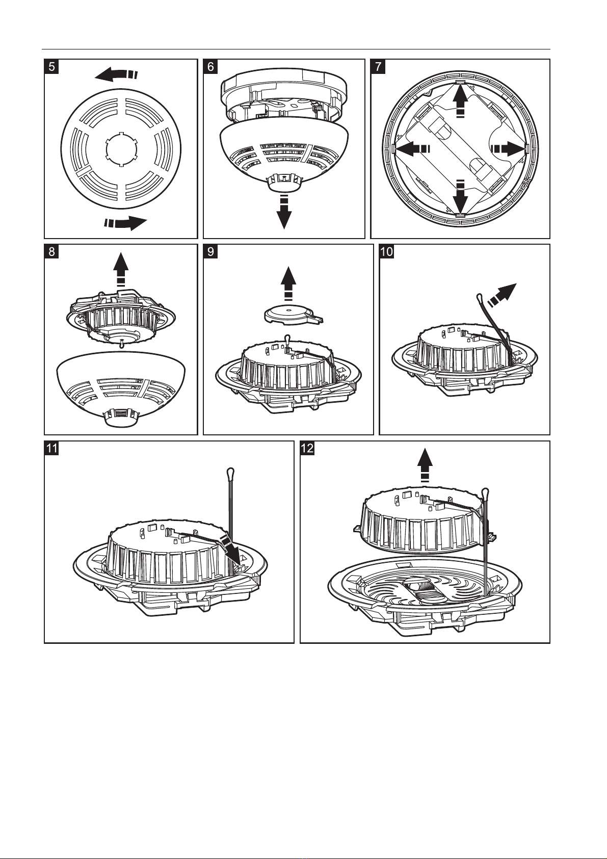
clean the chamber:
1. Turn the cover counter-clockwise (Fig. 5) and remove it (Fig. 6).
2. Pull aside the mounting catches (Fig. 7) and remove the electronics board with the optical chamber (Fig. 8).
3. Remove the cover from the thermistor (Fig. 9).
4. Pull aside the thermistor and its leads (Fig. 10).
5. Pull aside the mounting catch of the optical chamber (Fig. 11) and remove it (Fig. 12).
6. Using a soft brush or compressed air, clean the labyrinth in the cover and the base of the optical chamber,
paying attention to the recesses where the LEDs are installed.
7. Replace the cover of the optical chamber.
8. Place the thermistor leads in the respective grooves.
9. Replace the thermistor cover.
10. Secure the electronics board with the optical chamber in the cover mounting catches. The board must be
mounted so that the LED coincides with the light guide.
11. Replace the detector cover and turn it clockwise.
5. Specifications
Supply voltage ...................................................................................................................................12 V DC ±15%
Standby current consumption...................................................................................................................... 0.25 mA
Maximum current consumption ...................................................................................................................... 24 mA
Relay contacts rating (resistive load)..............................................................................................40 mA / 16 V DC
Class according to EN 54-5 (heat sensor)..........................................................................................................A1R
Minimum static response temperature .............................................................................................................54 °C
Maximum static response temperature ............................................................................................................65 °C
Environmental class according to EN50130-5 ........................................................................................................II
Operating temperature range ........................................................................................................... -10 °C...+55 °C
Maximum humidity..........................................................................................................................................93±3%
Enclosure dimensions.........................................................................................................................ø108 x 61 mm
Weight...............................................................................................................................................................164 g
The declaration of conformity may be consulted at www.satel.eu/ce

4 TSD-1 SATEL
SATEL sp. z o.o.
ul. Schuberta 79
80-172 Gdańsk
POLAND
tel. + 48 58 320 94 00
www.satel.pl
Table of contents
Other Satel Smoke Alarm manuals
Popular Smoke Alarm manuals by other brands

Aritech
Aritech 560 Series installation instructions

Jalo Helsinki
Jalo Helsinki Kupu Series Installation

WOXTER
WOXTER domotify DO26-009 user manual

Apollo
Apollo Smoke Detector XP95 Engineering Product guide

FireBrand
FireBrand CQR-338-2 Installation, Testing, Maintenance Instructions

Apollo
Apollo REACH WIRELESS RW1000-600APO quick start guide