SATEL DMP-400 / DRP-400 / DCP-400 3
In spaces where condensation of water vapor occurs, install the detector base on the
PDB-100 industrial base by SATEL.
Do not install the detector near heaters, cookers, fans or air-conditioner outlets.
Do not install the detector in places where there is no unobstructed movement of air
(e.g. in recesses, niches, etc.).
4 Installation
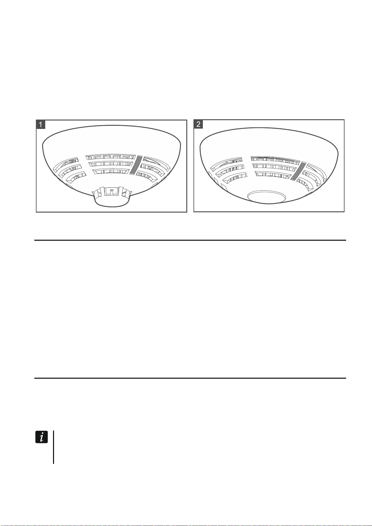
1. Place the detector in the base installed in the mounting location.
2. Turn the detector clockwise until you feel resistance.
3. If in the premises where the detector is installed, any work is being carried out that may
cause dirt to build up in the optical chamber, put a plastic dust cover on the detector and
leave it there until the work is finished.
5 Maintenance
The fire alarm system elements require regular maintenance. The periodic checks of the
DMP-400 / DRP-400 / DCP-400 detectors should be carried out at least every 6 months.
In spaces where working conditions are difficult (e.g. dust, aggressive environment that may
cause corrosion, etc.), the periodic checks should be carried out more often.
As part of maintenance, start a test in the control panel to make sure the detector is
functional and detects smoke / temperature rise. To test the smoke sensor, use the smoke
detector test spray. To test the rate-of-rise heat sensor, use the heat detector tester kit.
Please go to the ACSP-402 control panel manuals to find out how to start the test. Start of
the test and test activation of devices will be registered in the control panel event log. During
the test, make sure the device is in its right place (e.g. it has not been swapped with another
device).
6 Cleaning the optical chamber
It is recommended to clean the optical chamber at least once a year. Deposition of dust in it
may lead to malfunctioning of the device.
The following cleaning procedure applies to the DMP-400 detector. For the DRP-400
detector, in which no thermistor is installed, skip the steps 5 and 9.
1. Start the service mode in the control panel.
2. Turn the detector counter-clockwise (Fig. 3) and remove it from the DB-400 base (Fig. 4).
3. Pull the release lever to unlock the electronics module and turn it counter-clockwise
(Fig. 5 and 6).
4. Remove the electronics module with the optical chamber (Fig. 7).
5. Remove the plastic element with the thermistor from the optical chamber cover (Fig. 8).
6. Release the mounting catch (Fig. 9) and remove the optical chamber cover (Fig. 10).
7. Using a soft brush or compressed air, clean the labyrinth in the cover, as well as the base
of the optical chamber, paying attention to the recesses where LEDs are installed.
8. Replace the optical chamber cover.
9. Replace the plastic element with the thermistor on the optical chamber.
10.Secure the electronics module with the optical chamber in the cover and turn it clockwise.
11.Insert the detector into the DB-400 base and turn it clockwise.