Satel ASD-200 User manual

ASD-200
Wireless smoke and heat detector
Firmware version 1.00 asd-200_en 03/19
SATEL sp. z o.o. • ul. Budowlanych 66 • 80-298 Gdańsk • POLAND
tel. +48 58 320 94 00
www.satel.eu

IMPORTANT
The device should be installed by qualified personnel.
Prior to installation, please read carefully this manual in order to avoid mistakes that can lead
to malfunction or even damage to the equipment.
Changes, modifications or repairs not authorized by the manufacturer shall void your rights
under the warranty.
The rating plate of the device is located on the enclosure base.
SATEL aims to continually improve the quality of its products, which may result in changes in
their technical specifications and software. Current information about the changes being
introduced is available on our website.
Please visit us at:
http://www.satel.eu
Hereby, SATEL sp. z o.o. declares that the radio equipment type ASD-200 is in
compliance with Directive 2014/53/EU. The full text of the EU declaration of conformity
is available at the following internet address: www.satel.eu/ce
The following symbols may be used in this manual:
- note,
- caution.

The ASD-200 multisensor detector can detect the early stages of fire development when
there is some visible smoke and/or temperature rise. It is designed for operation within the
ABAX 2 / ABAX two-way wireless system. This manual applies to the detector with firmware
version 1.00, which is supported by:
ABAX 2:
– ACU-220 / ACU-280 controller,
– ARU-200 repeater.
ABAX:
– ACU-120 / ACU-270 controller (firmware version 5.04 or newer),
– ARU-100 repeater (firmware version 2.02 or newer),
– INTEGRA 128-WRL control panel (firmware version 1.19 or newer and firmware
version of processor used to operate ABAX system 3.10 or newer).
The detector is not a construction product as defined in Regulation (EU) No 305/2011
of the European Parliament and of the Council of 9 March 2011.
1 Features
Visible smoke sensor.
Detection of optical chamber fouling.
Heat sensor.
Built-in sounder.
Red LED for optical signaling.
Test feature.
Battery status control.
“ECO” option for longer battery life (ABAX 2 system only).
Encrypted two-way radio communication in the 868 MHz frequency band (AES standard
for the ABAX 2 system).
Transmission channel diversity – 4 channels for automatic selection of the one that will
enable transmission without interference with other signals in the 868 MHz frequency
band (ABAX 2 system only).
Remote update of detector firmware (ABAX 2 system only).
Tamper protection against enclosure opening.
2 Description
Radio communication
The detector connects to the controller / control panel at regular time intervals to provide
information about its state (periodical communication). Additional communication takes place
in the case of alarm (smoke / high temperature is sensed by the detector) or tamper (tamper
switch has been opened) and after restore of alarm (smoke / high temperature is sensed no
more by the detector) or tamper (tamper switch has been closed).

2 ASD-200 SATEL
Fire alarm
Smoke detection
An optical method is used for the detection of visible smoke. When the concentration of
smoke in the optical chamber exceeds a given threshold, an alarm is triggered. The smoke
sensor operating parameters are modified depending on the temperature changes recorded
by the heat sensor (thermistor). The detector automatically compensates for gradual changes
in the optical chamber caused by deposition of dust.
Temperature detection
The temperature exceeding 54°C or a too fast temperature rise (see table 1) will trigger an
alarm.
Air temperature rise
velocity Lower limit of response
time Upper limit of response
time
1°C/min 29 min 40 min 20 s
3°C/min 7 min 13 s 13 min 40 s
5°C/min 4 min 9 s 8 min 20 s
10°C/min 1 min 4 min 20 s
20°C/min 30 s 2 min 20 s
30°C/min 20 s 1 min 40 s
Table 1. Response time limits for the heat sensor.
Fire alarm signaling
The alarm is indicated visually (LED steady light) and acoustically (continuous sound) for 5
minutes. Pressing the test / reset button (Fig. 1) during the alarm will clear the alarm
condition.
Detector test
If you want to test operation of the detector, press the test / reset button (Fig. 1). A short
sound will be heard. After a few seconds, the fire alarm should be triggered.
Tamper
Opening the enclosure (opening the tamper switch) is treated as tamper.

SATEL ASD-200 3
Test mode
The test mode makes diagnostics of the detector easier, because the detector LED indicates
periodical communication and alarm memory. How to start and end the test mode is
described in the ABAX 2 / ABAX controller manual / the INTEGRA 128-WRL control panel
manual.
The alarm memory is cleared after ending the test mode.
LED
LED indicates:
low battery – 3 short flashes every 30 seconds,
alarm – ON for 5 minutes.
When the ABAX 2 / ABAX system is running in the test mode, the LED indicates additionally:
periodical communication – short flash (80 milliseconds), and when the chamber is soiled
- 2 short flashes,
memory of alarm triggered by smoke sensor – flashing rapidly,
memory of alarm triggered by heat sensor – flashing slowly.
Energy saving mode (ECO)
If you want to prolong the battery life, you can enable in the detector the “ECO” option. When
the “ECO” option is enabled, the periodical communication takes place every 3 minutes. Thus
the battery life can be increased as much as fourfold. The option is only available in the
ABAX 2 system.
Detection of optical chamber soiling
The detector is monitoring the state of the optical chamber. Deposition of dust in it may lead
to malfunctioning of the device. When the optical chamber requires cleaning, this state is
indicated by the LED.
Battery status control
When the battery voltage is lower than 2.75 V, the detector indicates low battery: 3 short
flashes of LED and 3 short beeps every 30 seconds. The low battery info is sent during each
transmission to the controller / control panel.
3 Selecting a mounting location
The detector is designed for indoor installation.
The detector should be installed in location close to the building / apartment exit (e.g. in
the hall, lobby etc. – Fig. 2 and Fig. 3).
In the typical home or office applications, the detector should be installed on the ceiling,
as close as possible to the center of the room, at a distance of at least 0.5 meters from
the walls or other objects (Fig. 4).
Do not install the detector in places with high concentration of dust and/or formation and
condensation of water steam.
Do not install the detector near heaters, cookers, fans or air-conditioner outlets.
Do not install the detector in places where there is no unobstructed movement of air (e.g.
in recesses, niches, etc.).

4 ASD-200 SATEL
It is not advisable to install it in close vicinity of electrical systems, because it can
adversely affect the range of radio signal.
Legend for Figures 2 and 3:
living room.
room.
hall, lobby, etc.
kitchen.
basement.
basic location for detector installation.
additional location for detector installation.
4 Installation
The detector enclosure can not be closed without the battery inserted.
Do not install the battery if the sounder is disconnected.
There is a danger of battery explosion when using a different battery than
recommended by the manufacturer, or handling the battery improperly.

SATEL ASD-200 5
Be particularly careful during installation and replacement of the battery. The
manufacturer is not liable for the consequences of incorrect installation of the
battery.
1. Remove the plastic dust cap.
2. Turn the cover counter-clockwise (Fig. 5) and remove it (Fig. 6).
3. Install the battery.
4. Add the detector to the wireless system (see the ABAX 2 / ABAX controller manual or the
INTEGRA 128-WRL control panel installer manual). The sticker with serial number which
shall be entered when registering the detector in the system can be found on the
enclosure base.
In the INTEGRA / VERSA alarm system, the detector is identified as ASD-110.
Simultaneous operation of the detector by the ABAX 2 and ABAX controller /
INTEGRA 128-WRL alarm control panel is not possible.
5. Replace the cover.
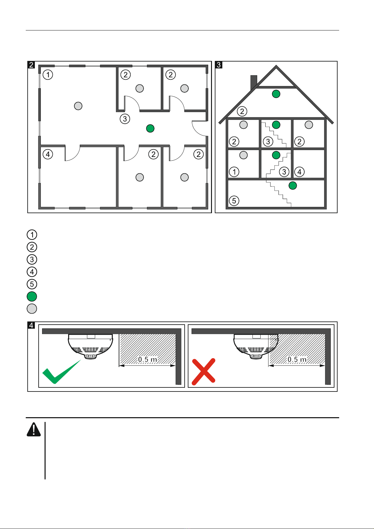
6. Put the detector at the place of its future installation.
7. Check the level of signal received from the detector by the ABAX 2 / ABAX controller or
the INTEGRA 128-WRL control panel. If the signal level is lower than 40%, select another
place for installation. Sometimes, it is sufficient to shift the device ten or twenty
centimeters to obtain a considerable improvement in the signal quality. You can also try to
turn the enclosure to check what effect the change of antenna position will have on the
signal strength.
The ARF-200 tester makes it possible to check the radio signal strength at the place of
future installation without having to put the detector there.
8. Remove the detector cover.
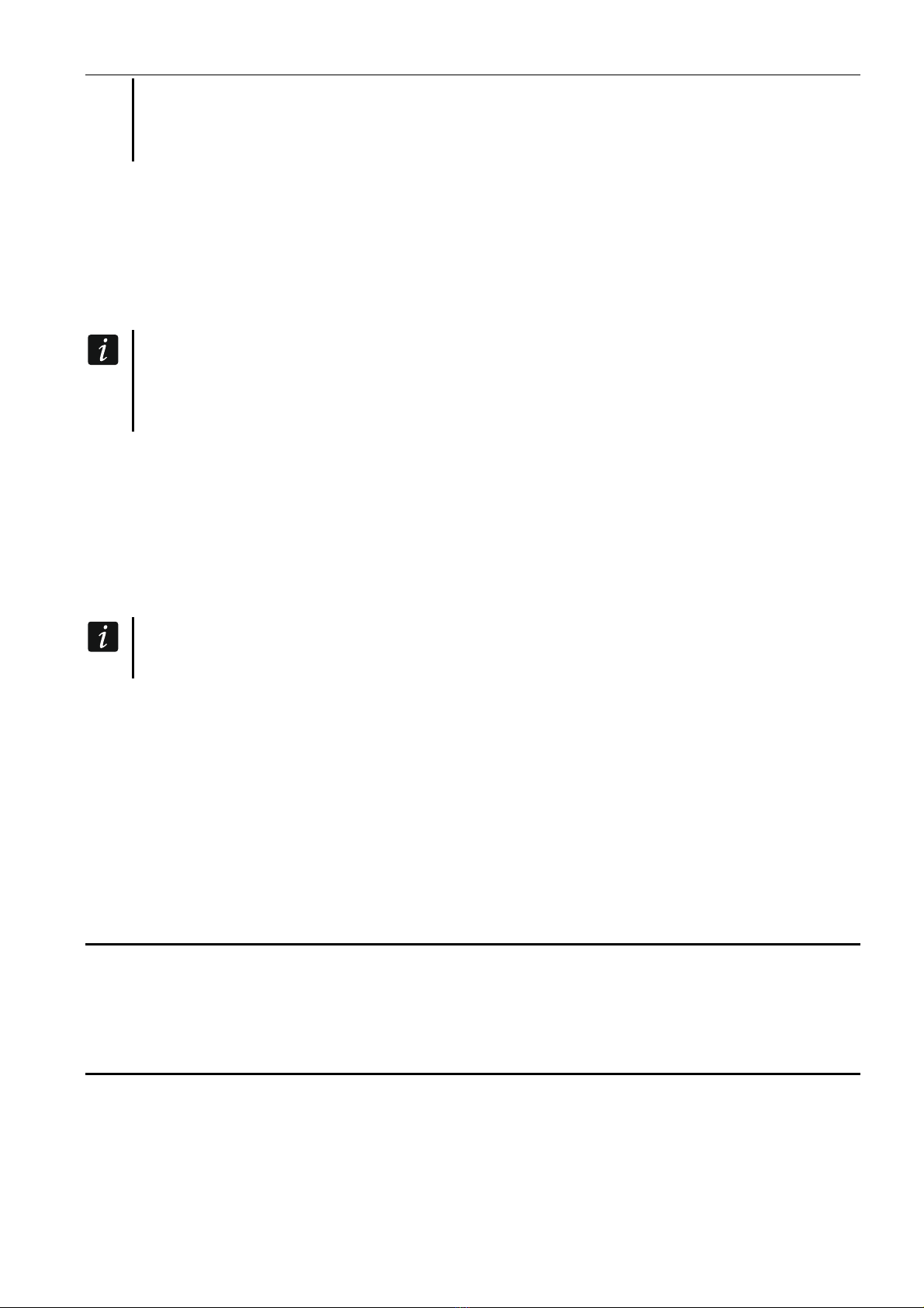
9. Use wall plugs (anchors) and screws to secure the enclosure base to the ceiling. The wall
plugs (anchors) delivered with the device are intended for concrete, brick, etc. For other
types of surface (drywall, styrofoam), use the appropriately selected wall plugs.
10.Replace the detector cover.
11.Press the test / reset button (Fig. 1). Fire alarm should be triggered.
12.If in the premises where the detector is installed, any work is being carried out that may
lead to soiling of the optical chamber, put a plastic dust cover on the detector and leave it
there until the work is finished.
5 Maintenance
The detector should be subjected to regular checks for correct functioning. The periodic
checks should be carried out at least every 6 months. To check whether the detector is
operating properly, press the test / reset button (Fig. 1). This should trigger a fire alarm.
6 Cleaning the optical chamber
It is recommended that you have the optical chamber cleaned at least once a year. Cleaning
the chamber is necessary when the LED indicates fouling of the chamber (2 short flashes
during periodical communication with controller / control panel).
1. Start the service mode in the control panel (if the controller is connected to a SATEL
alarm control panel).
2. Turn the cover counter-clockwise (Fig. 5) and remove it (Fig. 6).

6 ASD-200 SATEL
3. Remove the battery.
4. Pull aside the mounting catches (Fig. 7) and remove the electronics board with the optical
chamber (Fig. 8).
5. Remove the cover from the thermistor (Fig. 9).
6. Pull aside the thermistor and its leads (Fig. 10).
7. Pull aside the mounting catch of the optical chamber (Fig. 11) and remove it (Fig. 12).
8. Using a soft brush or compressed air, clean the labyrinth in the cover, as well as the base
of the optical chamber, paying attention to the recesses where LEDs are installed.
9. Replace the cover of the optical chamber.
10.Place the thermistor leads in the respective grooves.

SATEL ASD-200 7
11.Replace the thermistor cover.
12.Secure the electronics board with the optical chamber in the cover mounting catches. The
board must be mounted so that the LED coincides with the light guide.
13.Re-install the battery.
14.Replace the detector cover.
15.Press the test / reset button (Fig. 1). Fire alarm should be triggered.
7 Battery replacement
The used batteries must not be discarded, but should be disposed of in
accordance with the existing rules for environment protection.
When the detector indicates low battery (3 short flashes of the LED and 3 short beeps every
30 seconds), the battery must be replaced.
1. Start the service mode in the control panel (if the controller is connected to a SATEL
alarm control panel).
2. Turn the cover counter-clockwise (Fig. 5) and remove it (Fig. 6).
3. Remove the discharged battery.
4. Install a new CR123A 3 V lithium battery.
5. Replace the detector cover.
6. Press the test / reset button (Fig. 1). Fire alarm should be triggered.
8 Specifications
Operating frequency band ...................................................................868.0 MHz ÷ 868.6 MHz
Radio communication range (in open area)
ABAX 2
ACU-220 .............................................................................................. up to 2000 m
ACU-280 .............................................................................................. up to 1200 m
ABAX.............................................................................................................. up to 500 m
Battery ................................................................................................................... CR123A 3 V
Battery life expectancy.......................................................................................... up to 2 years
Standby current consumption ...........................................................................................30 µA
Maximum current consumption........................................................................................50 mA
Static response temperature.............................................................................................. 54°C
Operating temperature range.................................................................................... 0°C...55°C
Maximum humidity.......................................................................................................... 93±3%
Dimensions ......................................................................................................... ø108 x 54 mm
Weight............................................................................................................................... 170 g
Table of contents
Other Satel Smoke Alarm manuals
Popular Smoke Alarm manuals by other brands

SOMFY
SOMFY TaHoma 2401368 installation guide

CALECTRO
CALECTRO Uniguard Superflow UG-3-J Installation instruction

Jacob Jensen
Jacob Jensen S1201 user manual

netvox
netvox ZA01A user manual

System Sensor
System Sensor INNOVAIR DH100ACDCLWP Installation and maintenance instructions

Alecto
Alecto SA-41 instructions

LST
LST GM-55000-137 Specification sheet

Esel
Esel EL-2703 installation instructions

Notifier
Notifier SD-651A Installation and maintenance instructions

System Sensor
System Sensor BEAM1224 Installation and maintenance instructions

System Sensor
System Sensor D2-AUS Installation and maintenance instructions

Kidde
Kidde 914 user guide