Satelec Cocoon Spray User manual

Cocoon®/ Cocoon®Spray
User’s manual • Manuel d’utilisation
Bedienungsanleitung • Manuale d’uso • Handleiding voor de gebruiker

2

ENGLISH 4
FRANÇAIS 14
DEUTSCH 24
ITALIANO 34
NEDERLANDS 44
3

4
ENGLISH
ENGLISH

5
I - PRESENTATION AND INSTALLATION
Presentation 6
Technical description 6-7
Installation and use 7-8
II - MAINTENANCE AND STERILIZATION
Suprasson handpiece maintenance 8-9
Tip #1 maintenance 9
Micromotor maintenance 9
Unit maintenance 10
Fuse replacement 10
Trouble shooting 11-12
III - LIABILITY 13
IV - SYMBOLS 13
CONTENTS

I - PRESENTATION AND
INSTALLATION
1. 1 PRESENTATION
COCOON and COCOON SPRAY are devices specially
adapted for the veterinary practice. It includes
a micromotor and a multi-function ultrasound
generator.
Device are equipped with :
• 1 green flexible tube (2 m length) for
connection to a water source, fitted with an
impurity filter.
• 1 detachable mains cord + earth (2 m length).
• 1 single disconnectable pedal
• 1 AV40 micro motor
• 1 sterilisable ultrasonic handpiece
• 1 tip #1
• 1 handpiece support (Fig. 1-9)
• 1 micromotor support (Fig. 1-8)
• 1 water pump (avaible on option)
1. 2 TECHNICAL DESCRIPTION
a) Front panel (Fig. 1)
• ON/OFF switch (I/O) (Fig. 1-1).
• Power adjustment (Fig. 1-2).
• Range selection (motor/endo/scaling) (Fig. 1-
3).
• Spray adjustment (Fig. 1-4).
• Motor rotation reversal button (Fig. 1-5)
• Ultrasonic handpiece cord (Fig. 1-6)
• Micro-motor cord (Fig. 1-7)
6

b) Rear panel (Fig. 2)
• Pedal power socket (Fig. 2-1).
• Mains socket (Fig. 2-2).
• Fuses housing (Fig. 2-3).
• Flexible hose for connection to a water source
(Fig. 2-4).
c) Technical Data
Power supply : 230 VAC, 50/60 Hz
Class I equipment, BF Type
Fuses : 2 x 0.5 AT
Vibration frequency : 27 to 32 KHz
Water pressure : 1 to 5 bar (14.5 to 72.5 PSI)
Water filter : about 60 µm
Motor : 40000 rpm
Overall dimensions :
Depth : 180 mm Width : 230 mm
Height : 100 mm Weight : 3 Kg
Manufactured in accordance with Directive
89/336/EEC on electromagnetic compatibility.
1. 3 INSTALLATION AND USE
a) Recommendations
Before the unit is used for the first time, connect
the accessories and operate the spray for a few
minutes to rinse the water circuits inside the
instrument.
b) Connections
Rear panel of COCOON / COCOON SPRAY :
Connect :
• The green water inlet tube (Fig. 2-4) to the
water supply source or to the pump (depending
on option).
• The mains power cable must be plugged into its
socket (Fig. 2.2) and to a socket connected to
earth (according to country).
c) Commissioning and use
Motor support installation
Observe correct direction of assembly of the
micromotor support; if reversed, there is a risk of
breakage (Fig. 3).
Suprasson handpiece connection
Connect the handpiece by plugging it into the
cable socket.
Do not rotate.
Tip mounting
The Suprasson handpiece is a
high technology instrument
requiring precautions for use.
The tip must be screwed and
moderately tightened by
means of the corresponding
wrench.
CAUTION : Correct tip vibration requires
perfect tightening without overtorquing beyond
the thrust point. Remove the tip after each
procedure to avoid self-jamming.
Scaling with Tip #1
Interdentium treatment (Fig. 4A)
Tooth neck and subgingival treatment (Fig. 4B)
Tangential application
- Do not apply the tip extremity directly onto the
tooth.
- Apply the tip firmly without pressure.
- The Suprasson handpiece reciprocates slowly
and evenly.
Suprasson COCOON / COCOON SPRAY adjustment
Average values for indication only
Tip #1 Min. power : 1
Max. power : 10
7
!
D
D

Micromotor connection
Connecting the micromotor to its lead is done by
simply screwing it in.
The two red reference marks must be lined up.
COCOON SPRAY
Attach the tube delivered with the contra-angle
to the small L-shaped outlet connector on the
micromotor (1).
Spray adjustment is achieved via the front panel
(Fig. 1-4).
In the case of prophylaxis contra-angle utilisation,
close the front spray valve in order to stop the
flow of irrigation.
On the front panel there is a three position button
(Fig. 1-5) for reversal of the motor rotation :
Left selector : clockwise rotation
Right selector : anti-clockwise rotation
Centre selector : no rotation
II - MAINTENANCE AND
STERILISATION
The following maintenance and/or sterilization
instructions must be performed prior to any
initial use of the handpiece or of the tip
provided with the instrument.
2. 1 SUPRASSON HANDPIECE MAINTENANCE
a) Maintenance of the Suprasson handpiece
(Fig. 5)
Handpiece body must be cleaned and disinfected
(e.g. with alcohol : 96% V/V ethanol or dental
disinfecting towelettes). The threaded cavity can
be cleaned by means of a cotton swab soaked in
alcohol. The handpiece must not be cleaned in an
ultrasonic bath.
Caution : DO NOT disconnect the handpiece
while the instrument is powered and the
control pedal is activated.
b) Sterilization of the Suprasson handpiece
Sterilization conditions and cycles according to
equipment:
Equipment : autoclave
Wet heat sterilization:
134°C under 2 bar (200 kPa) for 20 min.
• Detach the handpiece from its connecting cord
and remove the tip.
• Wrap the handpiece in a sterilizable cloth or
pouch, as required.
• Remove the handpiece from the autoclave as
soon as sterilization is complete.
• Carefully dry the electrical contacts of the
handpiece and cable connector before
connecting them.
8
1

Caution :
•Prior to sterilization, use compressed air to
remove any irrigation fluid left in the
Suprasson handpiece.
•Always sterilize the Suprasson handpiece
without the tip installed.
• Because of use and successive sterilization
procedures, check the Suprasson handpiece for
any sign of external damage before you use it.
• The handpiece has an irrigation circuit gasket
ring in its rear part (1.15 x1) accessible and
visible thanks to a groove in the rear casing.
As a result, the gasket ring can be easily
replaced if it is damaged or excessively worn.
Have it replaced or replace it yourself (Ref.:
F12304: 3 water circuit gasket rings; F00070:
ring fitting tool). With subsequent
disconnections/re-connections and/or
sterilisations, this gasket ring should be
lubricated with dental instrument grease in
order to prolong its efficiency and prevent
internal leaks.
2. 2 TIP #1 MAINTENANT
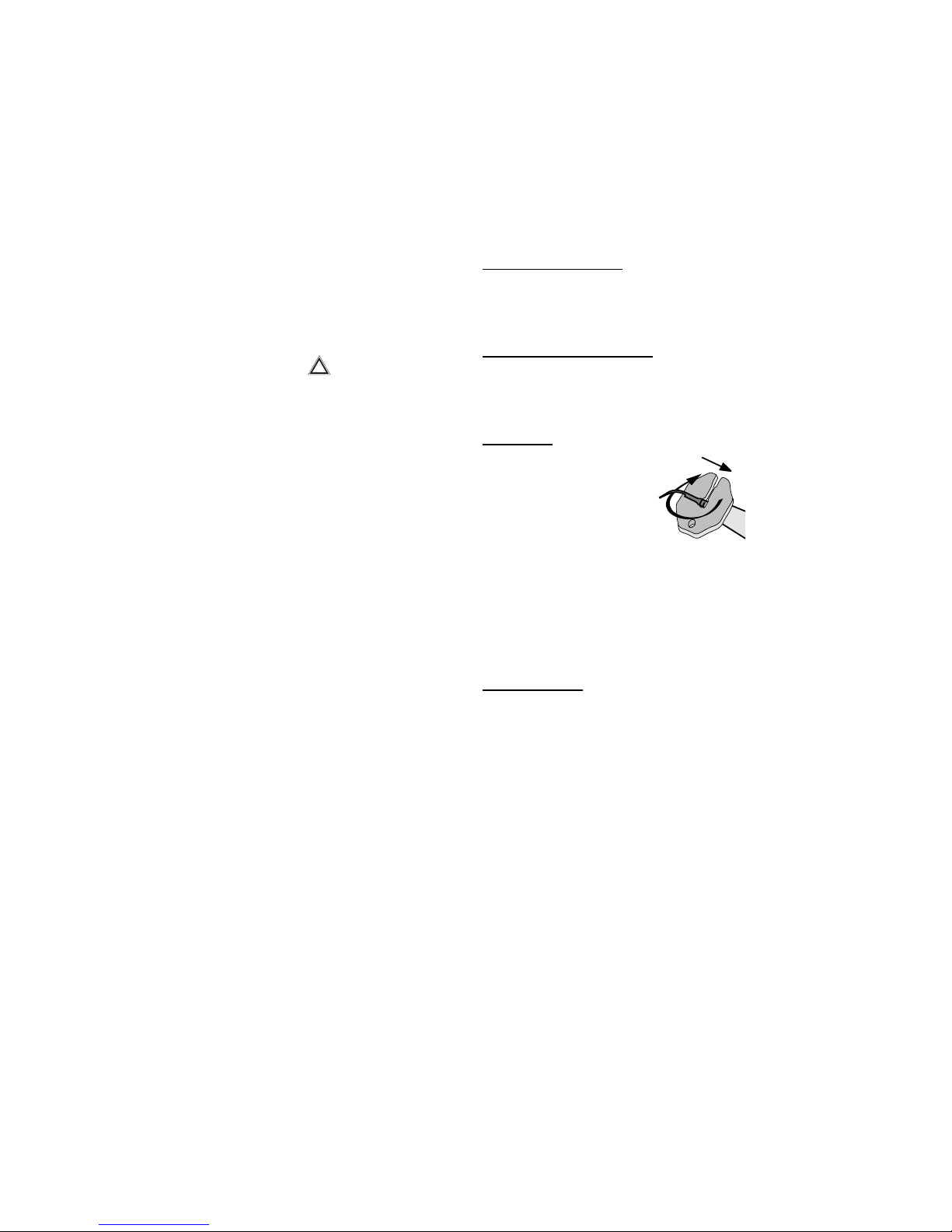
a) When is a scaling tip worn out ?
The shape and mass of the tip are determining
characteristics for achieving maximum ultrasonic
generator efficiency. Both characteristics should
be monitored in order to maintain the best
possible performance of the unit.
Therefore, it is strongly advised not to alter the
structure of a #1 tip by filing or bending.
Similarly, the ageing of tips simply due to normal
wear results in a change in their characteristics.
Tips damaged as a consequence of wear or
accidental impacts (fall, etc.) must be
systematically replaced.
b) Sterilization of #1 tip
All tips must be cleaned by using a cotton swab
soaked in alcohol or towelettes or by immersion
in an ultrasonic bath.
Tips can be sterilized by any conventional
thermal method.
Sterilization conditions and cycles according to
equipment :
Equipment: autoclave
Wet heat sterilization :
134°C under 2 bar (200 kPa) for 20 min.
When sterilizing handpiece and #1 tip, avoid
any contact between metallic parts of a
different nature as this would create
electrolytic couples liable to result in localized
deterioration. To avoid this phenomenon, wrap
the items in.
2. 3 MICRO-MOTOR MAINTENANCE
Cleaning and disinfecting
Caution : Do not disconnect the micro-motor
while the device is switched on and the control
pedal is engaged.
The micro-motor body must be cleaned and
disinfected (e.g. with alcohol: 96% V/V ethanol
and/or dental disinfecting towelettes) without
immersion.
The micro-motor and its connecting cable must
never be immersed in a solvent or in an ultrasonic
cleaning bath.
9

2. 4 UNIT MAINTENANCE
The COCOON / COCOON SPRAY case and the Suprasson
handpiece cord and micromotor cord can be
cleaned and disinfected with alcohol and/or
disinfecting towelettes as used in dental practice
(Fig. 6).
2. 5 FUSE REPLACEMENT
- Unplug the mains cord from the power outlet (Fig.
7-1).
- Insert a screwdriver end into the slot under the
three male pins of the mains socket (Fig. 7-3).
- Pull out and check the defective fuse(s).
- Replace the defective fuses as required with
fuses of the same type and rating (see page 7).
- Push the fuse holder back into its housing (Fig.
7-2).
2. 6 TROUBLESHOOTING
10

11
FAULT
No operation
No spray
No water at tip but
vibration present
Insufficient power
Low vibration
No ultrasonic output
Water leak between
handpiece and cord or at
front/back junction of
handpiece
REMEDY
• Check mains outlet
• Return to customer
service
• Dry any moisture, especially
on electrical contacts
• Check water supply
• Check pressure
• Clean or replace filter
• Return to customer
service
• Remove obstruction
• Adjust spray
• Replace tip
• See tip utilization method
• Wipe electrical contacts
dry
• Tighten with wrench
• Clean cord contacts
• Return to customer
service for cord
replacement
• Replace seal
POSSIBLE CAUSE
• Wrong mains cord connection
• Blown fuse
• Presence of fluid or moisture between
handpiece and cord
• Wrong water tube connection
• No water pressure
• Clogged filter or defective solenoid
valve
• Blocked tip
• Incorrect spray adjustment
• Worn or deformed tip
• Incorrect use: wrong angle of
application or inadequate pressure on
tooth
• Presence of fluid or moisture between
handpiece and cord
• Incorrect tip tightening
• Defective connector contact
• Cut wire in handpiece cord
• Worn sealing gasket (1.15 x 1) in
handpiece

12
FAULT
Motor will not run after the
pedal has been activated
No water output at contra-
angle
The luminous switch does
not light up
Rotation direction does not
match selection
REMEDY
• Plug in pedal cable jack
correctly
• Turn it to desined position
• Plug in motor cable jack
correctly
• Tighten motor cable jack
• Slightly raise the 2 blades
by means of a screwdriver
• Return to SATELEC
Customer Service
• Change cable
• Change pedal
• Change motor
• Check water input
• Check pressure
• Clean or change filter
• Return to SATELEC
Customer Service
• Remove obstruction
• Replace fuses
• Check micromotor for
correct assembly onto
connecting cable (red
mark)
POSSIBLE CAUSE
• Wrong pedal cable connection
• Motor rotation reversal button in
central position
• Wrong motor cable connection
• Motor cable jack loose on cable
connector
• Cable connector contact blades too
flattened
• Control box malfunction
• Cut cable
• Defective pedal
• Motor failure
• Water tube incorrectly connected
• Insufficient water pressure
• Blocked filter of faulty electrovanne
• Contra-angle blocked
• Micromotor water outlet connector
blocked
• Fuses blown
• Incorrect micromotor connection

III - LIABILITY
The manufacturer's liability shall not be
pledged in the following cases:
- Failure to respect the manufacturer's
instructions for installation (water pressure,
mains voltage).
- Maintenance or repair by persons not
authorized by the manufacturer.
- Use on an electrical installation that does not
comply with the regulations in force
• Other uses as those specified in this Manual.
- The manufacturer reserves the right to modify
the device and/or the instruction manual
without prior notice.
IV - SYMBOLS
Alternating current
BF Type
Caution, refer to accompanying
documents
13
3
~
3N
33N
33N
!
Secteur
Mains
Appareil de Classe
Class Equipment
Puissance absorbée
Input Power
Service
Operation
80 VA
I
!
50/60 Hz
230 V
Z.I du Phare 33708 MERIGNAC FRANCE
Made in France by
Intermittent
Pression d'entrée d'eau
Input water pressure 1 à 5 bars / 14.5 to 72.5 p.s.i.
APPAREIL DE PROPHYLAXIE
PROPHYLAXIS UNIT
V~
S/N˚

14
FRANÇAIS
FRANÇAIS

15
I - PRESENTATION ET INSTALLATION
Présentation 16
Description technique 16-17
Installation et utilisation 17-18
II - ENTRETIEN ET STERILISATION
Entretien de la pièce à main 18-19
Entretien de l'insert n°1 19
Entretien du micro-moteur 19
Entretien de l'appareil 20
Remplacement des fusibles 20
Anomalies de fonctionnement 21-22
III - RESPONSABILITÉ 23
IV - SYMBOLES 23
SOMMAIRE

I - PRESENTATION ET
INSTALLATION
1. 1 PRESENTATION
COCOON et COCOON SPRAY sont des appareils
spécialement adaptés à la clinique vétérinaire.
Ils comprennent un micro-moteur et un
générateur à ultrasons multi-fonctions.
Appareils fournis avec :
• 1 tuyau souple vert (2 mètres) pour liaison au
réseau d'eau, équipé de son filtre à particules.
• 1 cordon secteur amovible + terre (2 mètres).
• 1 pédale simple déconnectable
• 1 micro moteur AV40
• 1 pièce à main ultrasonique stérilisable
• 1 insert n°1
• 1 support de pièce à main (Fig. 1-9)
• 1 support micro moteur (Fig. 1-8)
• 1 pompe à eau (à commander en option)
1. 2 DESCRIPTION TECHNIQUE
a) Face avant (Fig. 1)
• Interrupteur Marche/Arrêt (I/O) (Fig. 1-1).
• Réglage de puissance (Fig. 1-2).
• Sélection gamme (moteur/endo/détartrage)
(Fig. 1-3).
• Réglage du spray (Fig. 1-4).
• Bouton inversion rotation moteur (Fig. 1-5)
• Cordon pièce à main ultrasonique (Fig. 1-6)
• Cordon micro-moteur (Fig. 1-7)
16

b) Face arrière (Fig. 2)
• Prise pédale (Fig. 2-1).
• Embase secteur (Fig. 2-2).
• Logement fusibles (Fig. 2-3).
• Tuyau souple pour liaison au réseau d'eau (Fig.
2-4).
c) Caractéristiques techniques
Alimentation : 230 VAC - 50/60 Hz
Equipement de Classe I, type BF
Fusibles : 2 x 0,5 AT
Fréquence des vibrations : 27 à 32 KHz
Pression d'entrée d'eau : 1 à 5 bars (14,5 à 72,5
PSI)
Filtre à eau : de l'ordre de 60 µm
Moteur : 40000 trs/mn
Dimensions hors tout :
Profondeur : 180 mm Largeur : 230 mm
Hauteur : 100 mm Poids : 3 Kg
Fabriqué en conformité avec la Directive
89/336/CEE relative à la compatibilité
électromagnétique.
1. 3 INSTALLATION ET UTILISATION
a) Recommandations
Avant la première utilisation du boîtier, il est
recommandé de brancher les accessoires et de
faire fonctionner le spray quelques minutes pour
rincer le circuit d'eau intérieur de l'appareil.
b) Raccordement
Face arrière du COCOON / COCOON SPRAY:
Raccorder :
• Le tuyau souple vert (Fig. 2-4) au réseau
d'alimentation en eau ou à la pompe à eau
(selon version).
• Le cordon secteur doit être connecté à son
embase (Fig. 2-2) et à une prise de courant
reliée à la terre (selon pays).
c) Mise en service et utilisation
Montage du support moteur
Bien respecter le sens de montage du support
micro-moteur, une inversion risquerait de casser
le support (Fig. 3).
Raccordement de la Pièce à Main Suprasson
Le raccordement de la pièce à main sur la douille
du cordon s'effectue par simple enfichage.
Ne pas effectuer de mouvement de rotation.
Montage des inserts
La pièce à main Suprasson est
un instrument de haute
technologie qui demande des
précautions d’utilisation. Les
inserts doivent être vissés et
serrés modérément avec leur
clé.
ATTENTION : La vibration correcte d'un insert
implique un serrage parfait qui ne doit pas être
forcé au-delà de son point de butée. Pour éviter
son auto-blocage, l'insert doit être démonté
après chaque utilisation.
Détartrage avec l'insert N° 1
Traitement du joint interdentaire (Fig. 4A)
Traitement du collet et sous-gingival (Fig. 4B)
Application tangentielle
- Ne pas appliquer la pointe directement sur la dent.
- L'insert est appliqué de manière franche sans
pression.
- La Pièce à Main Suprasson est animée d'un
mouvement de va-et-vient lent et régulier.
Réglage du COCOON / COCOON SPRAY
Valeur moyenne donnée à titre indicatif.
Insert n° 1 Puissance mini : 1
Puissance maxi : 10
17
D
D
!

Raccordement du micro-moteur
Le raccordement du micro-moteur sur son
connecteur cordon s'effectue par simple vissage.
Les 2 repères rouges doivent être en vis à vis.
COCOON SPRAY
Raccorder le tuyau livré avec le contre-angle au
petit tube du connecteur cordon du micro moteur
(1).
Le réglage du spray s'effectue en face avant
(Fig. 1-4).
En cas d'utilisation d'un contre-angle de
prophylaxie, fermer le robinet de spray en face
avant pour stopper le flux d'irrigation.
La face avant possède un bouton 3 positions (Fig.
1-5) pour inversion du sens de rotation moteur :
Sélecteur à gauche : sens de rotation horaire
Sélecteur à droite : sens de rotation anti-
horaire
Sélecteur au centre : pas de rotation
II - MAINTENANCE ET
STERILISATION
Les consignes d'entretien et/ou de stérilisation
qui suivent doivent être opérées avant toute
première utilisation de la pièce à main ou de
l'insert livré avec l'appareil.
2. 1 ENTRETIEN DE LA PIECE A MAIN
SUPRASSON
a) Entretien de la Pièce à Main Suprasson (Fig.
5)
Le corps de la pièce à main doit être nettoyé et
désinfecté (ex : alcool : éthanol 96° v/v et/ou
lingettes désinfectantes). La cavité du pas de vis
peut être nettoyée au moyen d'un coton tige
imbibé d'alcool. Ne pas effectuer le nettoyage de
la pièce à main dans une cuve à ultrasons.
Attention : Ne pas déconnecter la Pièce à Main
lorsque l'appareil est sous tension et la pédale
appuyée.
b) Stérilisation de la Pièce à Main Suprasson
Conditions et cycles de stérilisation selon matériel
:
Matériel : autoclave
Stérilisation sous chaleur humide :
134° C sous 2 bars (200 KPa) pendant 20 mn
- Déconnecter la pièce à main du cordon et
démonter l'insert
- Placer la pièce à main dans un tissu ou un
sachet stérilisable, si nécessaire.
- Sortir la pièce à main de l'autoclave dès la fin
de la stérilisation.
- Bien sécher les contacts électriques de la pièce
à main et du connecteur du cordon avant
connexion.
18
1

Attention :
• Avant stérilisation, chasser tout liquide
d'irrigation dans la Pièce à Main Suprasson à
l'aide d'air comprimé.
• La Pièce à Main Suprasson doit toujours être
stérilisée sans l'insert.
• Pour cause d'usage et de stérilisations
successives, vérifier avant utilisation que la
Pièce à Main Suprasson n'a pas été
endommagée extérieurement.
• La pièce à main détient dans sa partie arrière
un joint d'étanchéité du circuit d'irrigation
(1,15x1) accessible et visible grâce à une
échancrure de la douille arrière. Celle-ci
permet également le remplacement plus aisé
du joint en cas de blessure ou d'usure
excessive. Faites procéder ou procédez vous-
mêmes à son échange (Réf : F12304 : 3 joints
raccord d'eau ; F00070 : outil pose joint). Au
fil des déconnexions/reconnexions et/ou des
stérilisations, il est recommandé de lubrifier
ce joint avec une graisse pour
instrumentations dentaires afin de prolonger
son efficacité et éviter des fuites internes.
2. 2 ENTRETIEN DE L'INSERT N°1
a) Quand est-il hors d'usage ?
La forme et la masse de l'insert sont les
caractéristiques déterminantes pour obtenir le
rendement maximal du générateur à ultrasons. La
vigilance de l'utilisateur sur ces deux
caractéristiques permettra de conserver les
meilleures performances de l'appareil.
Il est donc, par conséquent, vivement
déconseillé de modifier la structure de l'insert
n°1 en le limant ou en le tordant.
De même, le vieillissement d'un insert entraîne
par phénomène d'usure normale, une
modification de ses caractéristiques.
Procéder systématiquement au remplacement
d'un insert qui a subi une détérioration par l'usure
ou par un choc accidentel (chute...).
b) Stérilisation de l'inserts N°1
Tout insert doit être nettoyé avant stérilisation
avec un coton imbibé d'alcool, des lingettes ou
par immersion dans une cuve à ultrasons.
La stérilisation des inserts est réalisable par
tous procédés thermiques conventionnels.
Conditions et cycles de stérilisation selon matériel :
Matériel : autoclave
Stérilisation sous chaleur humide :
134° C sous 2 bars (200 KPa) pendant 20 mn
Pendant la stérilisation de la pièce à main et de
l'insert, des pièces métalliques de nature
différente ne doivent pas se toucher. Tout
contact entraînerait la création de couples
électrolytiques qui provoqueraient une
détérioration locale. Afin d'éviter ce
phénomène, placer les objets dans un tissu ou
un sac stérilisable.
2. 3 ENTRETIEN DU MICRO-MOTEUR
Nettoyage et désinfection
Attention : Ne pas déconnecter le micro-moteur
lorsque l'appareil est sous tension et la pédale
de commande enclenchée.
Le corps du micro-moteur doit être nettoyé et
désinfecté (ex : alcool : éthanol 96 % v/v et/ou
lingettes désinfectantes) sans immersion.
Ne jamais tremper le moteur dans un solvant ni
dans une cuve à ultrasons.
19

2. 4 ENTRETIEN DE L'APPAREIL
Le boîtier du COCOON ainsi que le cordon de la
Pièce à Main et le cordon du micro-moteur
doivent être nettoyés et désinfectés (alcool et/ou
lingettes désinfectantes de cabinet dentaire)
(Fig. 6).
2. 5 REMPLACEMENT DES FUSIBLES
- Retirer la fiche secteur de son embase (Fig. 7-
1).
- Insérer la tête d'un tournevis dans l'encoche
située sous les trois broches mâles de l'embase
secteur (Fig. 7-3).
- Extraire et vérifier le ou les fusibles
défectueux.
- Procéder au remplacement des fusibles de
même valeur et de même type (voir page 17).
- Replacer le compartiment fusible dans son
logement en le poussant (Fig. 7-2).
2. 6 ANOMALIES DE FONCTIONNEMENT
20
This manual suits for next models
1
Table of contents
Languages: