SatisGeo KAPPAMETER KM-7 User manual

SatisGeo
instruments for geophysics & environment
OPERATION
MANUAL
2011
KAPPAMETER KM-7
Pocket Magnetic Susceptibility Meter

1
CONTENTS
1INTRODUCTION..................................................................................................3
1.1 Operation principles .........................................................................................3
1.2 Specifications....................................................................................................3
2OPERATION .........................................................................................................4
2.1 Power Supply....................................................................................................4
2.2 Turning On/Off.................................................................................................4
2.3 Control buttons.................................................................................................4
2.4 Items setting......................................................................................................5
2.5 Status icons.......................................................................................................5
2.6 Menu.................................................................................................................6
2.6.1 Introduction screen........................................................................................6
2.6.2 Main menu .................................................................................................... 6
2.6.3 Measuring .....................................................................................................7
2.6.4 Memory menu...............................................................................................8
2.6.5 Setup menu....................................................................................................8
Sensor setting.........................................................................................92.6.5.1
System menu..........................................................................................92.6.5.2
BT menu...............................................................................................102.6.5.3
2.7 Measurement setting up..................................................................................10
2.7.1 Measuring in Single mode..........................................................................10
2.7.2 Measuring in Scan mode.............................................................................11
2.7.3 Measuring in Scan remote mode.................................................................11
2.8 GPS setting up................................................................................................11
2.9 Error messages................................................................................................12
3KM-7 MAINTENANCE......................................................................................13
4THE KMDATA COMMUNICATION PROGRAM........................................14
4.1 The KMdata installation.................................................................................14
4.2 Repair or Remove...........................................................................................18
5THE KMDATA DESCRIPTION.......................................................................19
5.1 Data tab...........................................................................................................20
5.1.1 Command banner........................................................................................20

2
5.1.2 Database browser........................................................................................21
5.1.3 Data table ....................................................................................................22
5.2 Setup tab.........................................................................................................23
5.2.1 Setup-Program ............................................................................................23
5.2.2 Setup-Communication ................................................................................24
5.3 Scan Remote tab.............................................................................................24
6BLUETOOTH CONNECTION .........................................................................26
6.1 Standard Bluetooth connection.......................................................................26
6.2 Manual Bluetooth connection.........................................................................28
6.3 Declaration of Conformity..............................................................................29

3
1 INTRODUCTION
The pocket susceptibility meter KM-7 is designed for quick field measurements of
magnetic susceptibility of outcropping rocks, drill cores and larger pieces of rocks. The use of
KM-7 is especially advantageous for selecting of suitable specimens for further precise
laboratory studies of magnetic properties.
The KM-7 is designed for one-hand operation. A leather case can be worn on a waist-
belt.
1.1 Operation principles
The fundamental part of the instrument is an LC oscillator of 10 kHz, the inductivity of
which is embodied by a measuring coil situated at the active face of the instrument, the black
head. The susceptibility measurement is performed in three steps.
The frequency of the oscillator is measured with the coil at a distance at least 30cm
from the rock (initial measurement, AIR1), then with the coil applied to the rock surface
(SAMPLE) and again with the coils at a distance at least 30cm to achieve good sensitivity.
From the difference of the frequencies the susceptibility is computed and then displayed.
1.2 Specifications
Sensitivity: 1x10⁻⁶ SI units (1x10⁻⁵ SI units in scan mode or with pin)
Measuring ranges: from -999.9 to 999.9 x 10⁻³ SI units
with automatically switched range
Operating frequency: 10 kHz
Display: 4 rows, backlight
Data memory: 999 readings without GPS coordinates
ca 500 readings with GPS coordinates
Controls: 4 buttons: Escape, Enter, Up, Down
Interface: USB 2.0, Bluetooth
Power consumption: 8 mA (without Bluetooth or backlight)
< 0.1 µA when power off
Battery: 2x AAA alkaline or NiCd/NiMh
Operating temperature: from -20OC to +60OC
Dimensions: 165mm x 76mm x 30mm
Weight: 250g including batteries
Accessories: leather case, instruction manual, USB cable,
disk –communication program

4
2 OPERATION
2.1 Power Supply
KM-7 is powered by two batteries (alcaline) or accumulators, type AAA. The battery
compartment is located at the bottom part of the instrument, the polarity of batteries is shown
at the picture at the back side.
2.2 Turning On/Off
Press the Enter button to turn the KM-7 on. The KM-7 introduction screen is displayed,
see chapter 2.6.1.
Press the Escape button for approximately 3 seconds to turn the KM-7 off. The
instrument is automatically turned off after ca 40 seconds of inactivity. If the KM-7 is
connected to a PC via USB/Bluetooth, or connection to Bluetooth GPS is active, the
automatic turn off is disabled.
2.3 Control buttons
The KM-7 magnetic susceptibility meter is controlled by four buttons, Enter, Escape,
Up and Down.
Figure 2-1 KM-7
The Enter button is used for entering a sub menu, enabling editable items and activating
action items. The Escape button located at the opposite side terminates an action on editable
items without change or returns to the upper menu when pressed in a sub menu. The Up and
Down buttons are used to browse among menu items and select values from predefined
editable items, e.g. enable or disable backlight.

5
To see which item in the KM-7 menu is selected, arrow at the left side of the display is
used. The position of the arrow points to the selected menu item.
2.4 Items setting
The KM-7 setting items are of two types: items to select one of predefined choices and
items to set a numerical value. All items with choices display their actual values. After Enter
button is pressed for the selected item, the original value is inverted and with the Up and
Down buttons the desired value can be selected. In case of the numerical values, the value is
incremented or decremented respectively. After the Enter button is pressed, the selected value
is stored to the KM-7 memory and a respective action is taken, e.g. Bluetooth is turned on. If
Escape button is pressed, the value of the item is not changed and the control is returned back
to the menu.
The arrow located at the left side of a menu shows which item is selected.
2.5 Status icons
The KM-7 uses several status icons. They can be seen on the right side of the display in
any of the KM-7 menus and sub-menus.
The battery icon displays battery status.
Figure 2-2 KM-7 battery status icon
The other icons that can be seen on the KM-7 screen show a connection status. If the
KM-7 is connected to PC via USB cable, the USB icon appears.
Figure 2-3 USB connection icon
If the Bluetooth is enabled, the Bluetooth icon appears, see Figure 2-4. Note only one
connection icon can be visible at a time, because only one type of connection can be
established at a time. The USB connection has the higher priority than the Bluetooth
connection. When the Bluetooth connection is active and the USB cable is connected, the
connection type is changed to the USB connection.
Figure 2-4 Bluetooth connection icon
If the KM-7 connection to the PC is established (via USB or Bluetooth) and is active
(program KMdata), the PC icon appears.
Figure 2-5 PC communicating icon

6
In the case that Bluetooth GPS is enabled in Setup>BT ON and connection type is set to
GPS in Setup>BT menu>BT GPS, the GPS satellite icon appears when valid GPS data are
received, see Figure 2-6. In the case of single mode measurement with GPS enabled, this icon
appears after measurement, indicating that the actual measurement can be saved with the
actual and valid GPS data. Otherwise valid and actual GPS data has not been received from
GPS and measurement can not be saved with GPS data.
Figure 2-6 GPS satellite icon
2.6 Menu
KM-7 menu has four levels:
Figure 2-7 KM-7 menu structure
2.6.1 Introduction screen
The KM-7 introduction screen is visible for ca 3 seconds after the instrument has been
switched on. Then the KM-7 goes to the main menu. The introduction screen can be left by
pressing any button as well.
2.6.2 Main menu
The main menu is composed of three items. Real time is displayed at the bottom line.
MEASURE PIN
MEMORY
SETUP
12:04
Figure 2-8 Main menu

7
The second item in main menu is a link to the Memory menu, see chapter 2.6.4.
The third item is a link to the Setup menu, see chapter 2.6.5.
2.6.3 Measuring
The first item is Measure. On the right side of this item, an actually selected
measurement sensor is indicated (FLAT, PIN, CORE). This can be changed in the Setup
menu.
If Enter button is pressed when Measure selected, the user is requested to set one of
three modes of measurement:
1. Single –one measurement.
2. Scan –data are continually measured and results are displayed on the display only.
3. Scan remote –continual measurement, where the measured data are transferred to
the PC via USB or Bluetooth and processed by the program KMdata.
After the mode of measurement is set, the initial measurement can be done (at least
30cm distance from a sample or other materials). This is indicated on the display by “AIR1”
notice. In the case the Escape button is pressed, the main menu is displayed. If button Enter is
pressed, the initial measurement is taken and “SAMPLE”is displayed to indicate that the
initial measurement is done, and the KM-7 can be put to the sample to measure its
susceptibility. In the case the Escape button is pressed, the “AIR1”notice is displayed again.
The selected sensor is indicated at the bottom line.
SAMPLE
Sensor: PIN
Figure 2-9 Ready for measuring
If the “SAMPLE”indicator is displayed and Enter button is pressed, the susceptibility
of the sample is measured. During the time of collecting signal, which takes ca 0.5s, the icon
Mis displayed at the left upper corner of the display and the beep is heard. Please do not
move the instrument when the Mis on. To complete the measurement, the third step is
required, again the measurement at least 30cm far from solid materials, see the notice
“AIR2”. The timeout between the steps is 10s. If the measurement is not completed by the
time, the notice “AIR1” is displayed and the kappameter is ready to start anew. If the set of
the three measurements are completed properly, the value of susceptibility is displayed, see
Figure 2-10. Mem indicator (left side) specifies location in the Memory menu, Loc indicator
(middle bottom) shows the user predefined location number. This can be set in the Memory
menu. Now, if the Enter button is pressed, the measured value is stored to the KM-7 memory,
if the Escape button is pressed, the measurement is lost. A new measurement can be taken.
0.239E-3 SI
Mem:008 Loc: 10 PIN
Figure 2-10 Results

8
2.6.4 Memory menu
The Memory menu, see Figure 2-11, integrates all action linked to the nonvolatile data
memory, like browsing the stored data and erasing the memory. The location of measurement
can be set.
LIST
ERASE
LOCATION 10
Mem. free 965
Figure 2-11 Memory menu
The first item List allows to view a stored data. If this item is selected and Enter button
is pressed, the most recently stored reading can be seen, see Figure 2-10. The measured value
is displayed in the center. Position in memory indicated by Mem, user defined location by Loc
and used sensor are displayed at the bottom line.
If the data was measured with GPS enabled, indicated by left arrow in the bottom left
corner in display, then GPS coordinates can be displayed by pressing Enter button,see Figure
2-12. To go back to the data view, Enter button must be pressed again.
Lat: 49°14´31.07´´N
Long: 16°34´42.79´´E
Alt: 315.5m
Figure 2-12 Memory list, GPS coordinates
To walk through stored items, Up and Down buttons are used. The Down button goes to
older data, Up button goes to newer data. If Up or Down button is pressed for a few seconds,
the move is faster. Escape button returns the control to the Memory menu.
The second item is Erase. All data stored in the KM-7 nonvolatile memory can be
deleted. Confirmation of this operation is required, otherwise this action is canceled.
The third item allows to set a measurement location, as described in chapter 2.4.
The last line shows free memory (number of readings without GPS data). Readings with
GPS coordinates are two times longer.
2.6.5 Setup menu
Various features of the KM-7 and measurement can be set up, see next chapters.
SENSOR PIN
SYSTEM
BT OFF
Figure 2-13 Setup menu

9
Sensor setting2.6.5.1
The first item of the Setup menu allows to select a sensor (PIN, FLAT, CORE), for
editing see the chapter 2.4Chyba! Nenalezen zdroj odkazů..
The value measured with the KM-7 depends on the size and shape of the sample.
The instrument KM-7 is calibrated for the idealized case in which the pick-up coil is
attached to an absolutely smooth plane confining a half-space filled with magnetically
homogeneous and isotropic medium. Then the displayed value of the susceptibility is the true
value. (The true value of susceptibility is computed in the microprocessor from the measured,
so called apparent, susceptibility.) If the sample is smooth enough and large enough, the
sensor FLAT may be used. It is not recommended to measure samples less than 50 mm thick,
with a surface smaller than the KM-7 face (60 mm).
However, often only rough surfaces of rocks are available for measuring. In that case, it
is recommended to use PIN option. The small (0.5cm long) pin screwed to the head of the
KM-7 defines the position of the pick-up coil –the distance from the surface, which may give
more precise results. The surface of the rock should be paralel to the surface at the head of the
instrument. The instrument is calibrated for the option. The measured value does not require
any corrections. Sensitivity of the measurement is limited to 1x10⁻⁵ SI units.
In measuring on outcrops it is necessary to consider the degree of weathering of the
surface which affects the results considerably. The weathering effect can hardly be evaluated;
therefore measuring on unweathered though less smooth surface is preferred.
In measuring drill cores, it is recommended to attach the pick-up coil to the side rather
than to the head of the core, since the core side is an almost perfectly smooth cylindrical
surface, while the head is uneven and usually of a small diameter. It is essential that the
cylinder measured be longer than 100 mm. The values measured on a cylindrical surface are
again the true values because the instrument is calibrated for the various diameters. When
selecting CORE, the user is requested to set the diameter of the core.
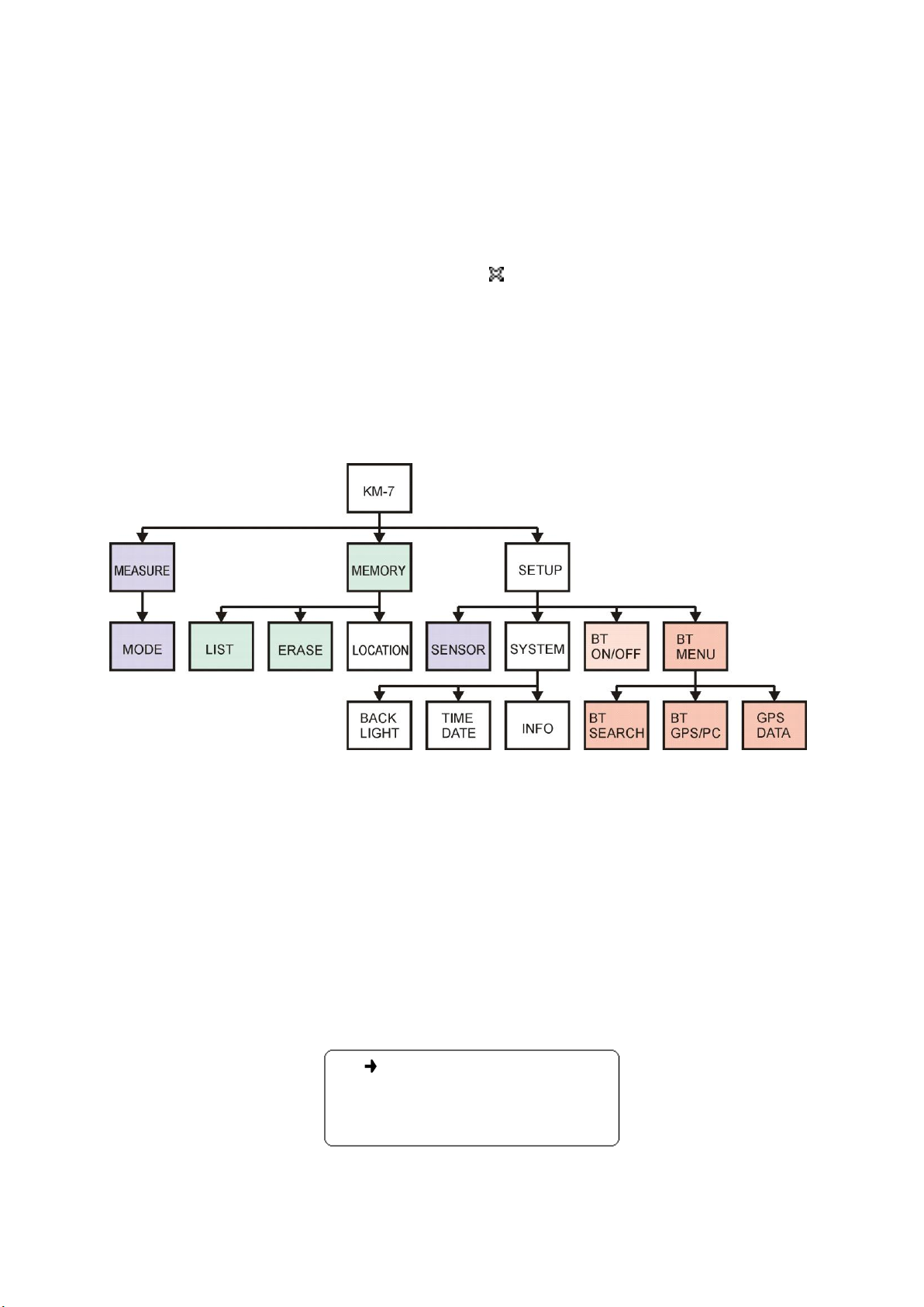
System menu2.6.5.2
Various settings of KM-7 are available:
BACKLIGHT ON
TIME/DATE
INFO
Figure 2-14 System menu
The first item allows to disable or enable the backlight of the display. If the backlight is
enabled, it is automatically turned off after ca 10 seconds of user’s inactivity. It is turned on
by pressing a button. The backlight ON increases the power consumption ca three times.
Setting the current time and date in the instrument can be done here (time/date) or by
a PC in the KMdata program (Synchronize time). The values of hours and minutes are
incremented and decremented by pressing Up and Down buttons. Enter button moves the
control to the next item. To set the date, similar way of editing is used. To exit the time and
date setting without changes, pres Escape button. Seconds are set to zero after all time and
date values are set and confirmed by the last Enter.
Info displays manufacturer, device name, serial number and firmware version.

10
BT menu2.6.5.3
The third item of the Setup menu enables/disables Bluetooth connection. In the case
Bluetooth is enabled, the forth line BT MENU is displayed. This is disabled if USB cable is
connected to the KM-7.
In the BT (Bluetooth) menu, all actions regarding the Bluetooth control are to be
accessed.
SEARCH
BT GPS
GPS DATA
Figure 2-15 BT MENU
The first item allows searching for Bluetooth devices. All devices in the range are
searched, and the user must select the Bluetooth GPS (most likely the GPS will be in its
name) from a list of found devices. The search process displays maximum four devices. If
SEARCH is selected and Enter button is pressed, the KM-7 begins searching for devices in the
range, and the progress is indicated by dots. This action takes ca 40 seconds and can not be
canceled.
If no device is found, BT device not found is displayed and Escape button must be
pressed to get back to the BT menu. Otherwise, list of found devices and their names is
displayed. The user can select the desired Bluetooth GPS by Up and Down buttons and press
the Enter button to use the selected device as the default GPS data source or press the Escape
button to end without changes.
The second item of the BT menu allows selection of the connection:
1. PC connection –the PC connection to the KM-7 and communication with KMdata
is established
2. GPS –the KM-7 connection to the default Bluetooth GPS
The third item displays current GPS data, see Figure 2-12. KM-7 must be set up for
connection to a Bluetooth GPS, and the Bluetooth GPS must be turned on.
2.7 Measurement setting up
To set up parameters for a measurement and conduct the measurement, follow the
instructions bellow. For further details, see chapters above.
2.7.1 Measuring in Single mode
Set sensor (Flat, Pin, Core) in Setup menu. Be sure the pin is properly screwed to the
head when setting PIN.
When measuring with GPS, make sure the USB cable is disconnected, set BT ON in
Setup menu, set BT GPS in BT MENU, turn on the GPS and wait for connection.
When measuring without GPS, set BT OFF in Setup menu.
Select Measure in main menu, set Single mode. Measuring is done in three steps, with
maximum 10 s between them.
1. AIR1 is displayed, KM-7 is ready for an initial measurement with the instrument
placed minimum 30 cm far from the sample, press Enter

11
2. SAMPLE is displayed, place the black head of the instrument paralel to the surfice
of the sample, press Enter
3. AIR2 is displayed, ready for the final measurement with the instrument placed
minimum 30 cm far from the sample, press Enter
Do not move instrument while the icon Mis displayed (collecting signal ca 0.5 s).
Save the displayed value by Enter, delete it by Escape.
Repeat the three steps or finish by Escape.
2.7.2 Measuring in Scan mode
Set sensor (Flat, Pin, Core) in Setup menu.
Select Measure in main menu, set Scan mode.
AIR1 is displayed. Make an initial measurement: Place the instrument minimum 30 cm
far from the sample, press Enter.
SAMPLE is displayed. Place the black head of the instrument paralel to the surfice of
the sample, press Enter.
Measuring at the sample is repeated until Escape. Move the KM-7 along the sample
according to your needs. Values of susceptibility are displayed, but not saved to
memory.
2.7.3 Measuring in Scan remote mode
Set sensor (Flat, Pin, Core) in Setup menu.
When using Bluetooth, set BT ON in Setup menu and BT PC in BT MENU, otherwise
connect USB cable.
Run program KMdata on PC, connect to the KM-7, go to Scan remote tab of KMdata.
Wait for the connection –check the icon.
Select Measure in main menu, set Scan remote mode.
AIR1 is displayed. Make an initial measurement: Place the instrument minimum 30 cm
far from the sample, press Enter.
SAMPLE is displayed. Place the black head of the instrument paralel to the surfice of
the sample, press Enter.
Measuring at the sample is repeated until Escape. Move the KM-7 along the sample
according to your needs. Values of susceptibility are displayed and sent to PC.
2.8 GPS setting up
Before using GPS for the first time, the device must be bounded (paired) with the KM-7.
This process can be done in any state of Bluetooth connection. After the search is completed,
the original state of connection is restored. The connection is then established to the newly
selected Bluetooth GPS.
Note if Bluetooth GPS is not a part of the package, this process must be done before the
Bluetooth GPS can be used and or after a new Bluetooth GPS is used.

12
Instructions: Go to the Setup menu and enable Bluetooth. In the BT menu search for
devices in the range. Wait for ca 40 seconds until the search process is completed. Select the
Bluetooth GPS by name and press Enter.
2.9 Error messages
Error messages are self-explanatory. In most cases, pressing Escape button solves the
problem. Sometimes removing batteries and inserting them again helps. If the failure persists,

13
3 KM-7 MAINTENANCE
Caution: The instrument can be damaged by a strong static charge.
If any operation described in this manual cannot be executed, check the battery, the
cleanness and quality of the contacts that connect the battery with the electronics. If both the
battery and the contacts are in a good condition, and the failure still persists, it is necessary to
ship the instrument for repair to the producer:
SatisGeo, s.r.o.
Jecna 29a
621 00 Brno
Czech Republic

14
4 THE KMdata COMMUNICATION PROGRAM
The KMdata communication program allows data transfer from KM-7 to PC. The
transferred data are stored in the internal program database. In the Scan remote mode,
KMdata allows direct acquisition of measurements from the KM-7. The data can be accessed,
displayed, sorted and exported.
The built-in tree xml database can be used in other programs for a further data
processing.
4.1 The KMdata installation
Run Setup from the installation CD, if it does not start automatically. This installation
program installs the KMdata program and all components to the PC. The USB drivers are
installed as well. To install USB drivers, you windows account must have administration
privileges.
After program installation starts, you may see following screen, Figure 4-1, if the .Net
Framework is not installed on you PC.
Figure 4-1 .NET framework installation window
After accepting the license agreement, .Net framework is installed.
Then the KMdata installation guide starts, see Figure 42.

15
Figure 4-2 KMdata welcome installation window
To continue the installation, click on the Next button. In the next window, installation
folder and Windows user account to where KMdata will be installed can be selected. The
necessary disk space for installation of the KMdata can be seen by clicking on the Disk Cost
button.
Figure 4-3 Installation folder selection

16
The installation must be confirmed.
Figure 4-4 Installation confirmation
If the installation is confirmed, the window with installation progress is displayed.
Figure 4-5 Installation progress

17
The result of installation is displayed.
Figure 4-6 Installation complete
The USB drivers are necessary for communication with KM-7 via USB. The drivers are
installed by KMdata installation program and can be found as well in the program installation
folder. To successfully install the USB drivers, the KM-7 must be connected via USB cable.
This action must be done before the first run of the KMdata.
Figure 4-7 USB driver installation

18
4.2 Repair or Remove
After the KMdata is installed, the installation program can be run again and remove
(uninstall) or repair the KMdata program.
Figure 4-8 Repair, Remove

19
5 THE KMdata DESCRIPTION
The KMdata program consists of three main windows/tabs and About tab.
The Data tab window, see Figure 5-1, is the first window that appears after the program
has started. Four tabs are to be found at the top left side of the main window. Data tab
provides access to a stored data. Setup tab incorporates all program setups and the KM-7
firmware update guide. Scan Remote tab, which is accessible only if the KMdata is connected
with KM-7, is used to acquire data from KM-7 in the Scan Remote mode. About tab shows
information about program.
The program window is divided to three main regions (except for the Setup tab). The
command banner is to be found under tabs, the status banner at the bottom of the window and
the main window of the selected tab is located in the middle of the program window.
The status banner is visible on all tabs. On the left side of status banner, the KM-7 serial
number is displayed. The progress bar is visible only when an action is taken e.g. transfering
data from KM-7, loading huge amount of data from the database to the table, etc.
Figure 5-1 KMdata main window
On the right side of status banner, a connection status icon can be seen.
Figure 5-2 Connection status icons: disconnected, Bluetooth connection, USB connection
Other manuals for KAPPAMETER KM-7
1
Table of contents
Other SatisGeo Measuring Instrument manuals