Satloc Falcon User manual

L8 Lightbar Installation Guide 875-3006-000 Rev A1
L8
Installation
Guide
Overview: This installation guide lists
all the parts in an L8 Kit and provides
step-by-step instructions on installing
the L8 lightbar.

L8 Lightbar Installation Guide 875-3006-000 Rev A1
1
Read and Follow Safety Messages
• In these instructions, you may see the heading and/or the safety alert symbol . They indicate a hazardous situation
that, if not avoided, could result in death or serious injury. The safety messages provide information to identify a hazard associated
with potential injury.
• Read and understand this manual and all the warnings below before installing, operating, or performing maintenance or service.
FAILURE TO DO SO MAY CAUSE IRREVERSIBLE DAMAGE TO YOUR SYSTEM.
• Keep this manual and all related safety information with the manuals for your aircra.
Plan your installation by considering the following: 1) cable lengths, 2) clearance space, 3) power source, 4) aircra
structure, and 5) visibility.
Consider using existing hardware and hardware locations. Avoid drilling holes that may damage other equipment
(such as structural frame members, electrical cables, or fluid lines).
Do not obstruct the view of, or access to, other instruments or the flying visibility of the operator.
Do not allow anyone to operate without instruction.
Safety Information 1
Kit P/N Information 1
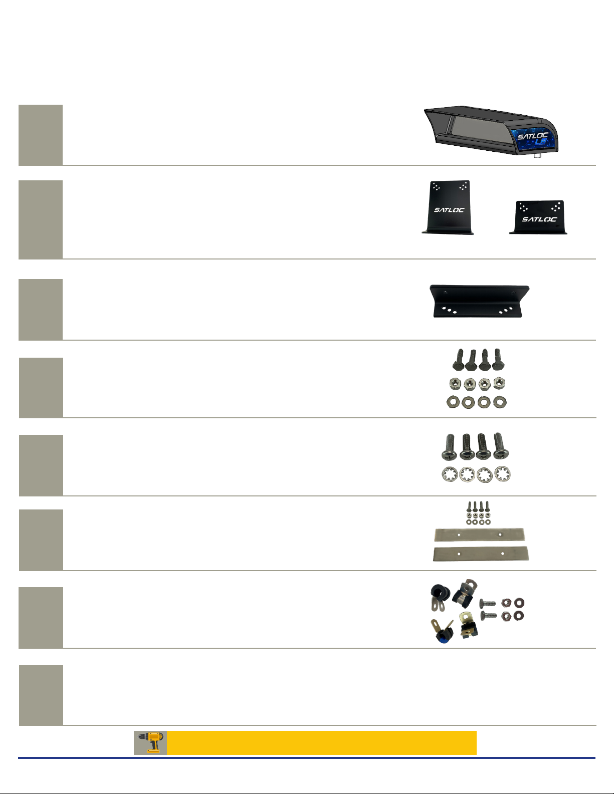
Kit Contents 2
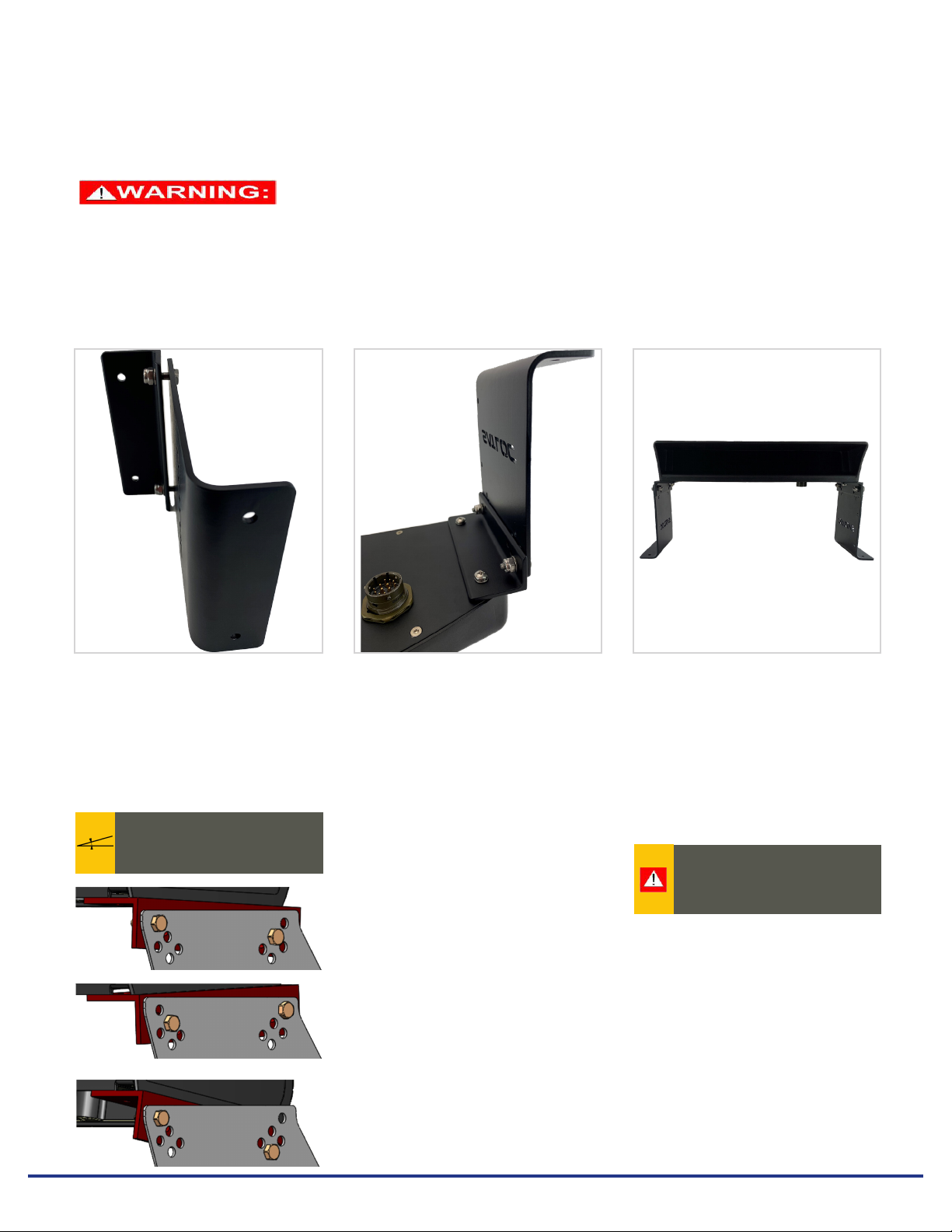
L8 Lightbar Installation Instructions 3-4
Technical Support 5
Coypright Notice
Satloc, a company of Texas Transland, LLC
Copyright Satloc © (2021). All rights reserved.
No part of this manual may be reproduced, transmitted, transcribed, stored in a retrieval system or translated into any language or computer language, in
any form or by any means, electronic, mechanical, magnetic, optical, chemical, manual or otherwise, without the prior written permission of Satloc.
Latest Version of the L8 Installation Guide
Satloc is dedicated to providing updated versions of installation guidebooks for its customers. Scan the
QR code to verify you have the latest version of the L8 Installation Guide or click this link to make sure
this is the latest version www.satlco.com.
Table of Contents
Safety Information
L8 Installation Kits
Kit P/N Information
Falcon G4 Bantam Optional Wingman
Bracket Kit
900-4300-000 900-4301-000 900-4302-000 710-0032-000
L8 Installed,
Upgrade to Falcon GPS
L7 to L8,
Upgrade for G4
L7 to L8,
Upgrade for Bantam
900-4307-000 900-4303-000 900-4304-000

L8 Lightbar Installation Guide 875-3006-000 Rev A1
2
REF
602-1014-000
602-1012-000
602-1016-000 (RH) &
602-1017-000 (LH)
QTY
Lightbar brackets, standard, 5.25"
Lightbar brackets, short, 3"
Lightbar brackets, Wingman, 7.5" (RH
and LH)
PART NUMBER
2
2
Optional
DESCRIPTION PHOTOGRAPH
B
C
E
F
G
H
602-1018-000 Top bracket
2
Bolt, #10-32 x 21/32"
Nut, #10-32
Washer, #10-32
4
4 (of 10)
4 (of 10)
*80922
*81202
Screw, #10-32 x 5/8"
Washer, Internal Lock, #10-32
4
4
*80013
*80570
*81219
*601-1045-000
Bolt, #10-32 x 25/32"
Nut, #10-32
Washer, #10-32
Backing plate
4
4 (of 10)
4 (of 10)
2
*86071 OR * 86436
*80007
*80570
*81219
Adel clamp
Bolt, #10-32 x 17/32"
Nut, #10-32
Washer, #10-32
2
2
2 (of 10)
2 (of 10)
L8 Lightbar cable for Falcon
L8 Lightbar cable for G4
L8 Lightbar cable for Bantam
Connects Lightbar Cable to GPS
*80011
*80570
*81219
D
Kit Contents
A drill and 1/4" drill bit are required for this installation.
AL8 for Falcon GPS
L8 for G4 GPS
L8 for Bantam GPS
1
806-4400-000
806-4401-000
806-4402-000
Wingman L8 bracket not pictured
*Part of Hardware Kit
P/N 710-2003-000
050-2205-000
050-2524-000
050-2523-000
1
1
1
Not Pictured

Tilting of lightbar brackets
is available in 2.5 degree
increments. Plus or minus 10
degrees. Examples shown below.
-2.5°
10°
L8 Lightbar Installation Guide 875-3006-000 Rev A1
3
Step One
Assemble Lightbar
Mounting Brackets
Do not hit any wires or
hydraulics while drilling. Check
both sides of the aircra before
drilling.
L8 Lightbar Installation Instructions
Do not obstruct the view of, or access to, other instruments or the flying or driving visibility of the operator.
Using hardware D, assemble two
mounting brackets using parts B
and C.
Note: There are three size options
for the mounting brackets.
Using the assembled lightbar and
brackets as a template, mark the
four mounting hole positions on
a suitable surface/location on
the aircraft. Using a 1/4" drill bit,
carefully drill the four holes.
Using hardware E, attach the
two mounting brackets to the
Lightbar.
Step Two
Attach Mounting Brackets
to Lightbar
Step Three
Marking Holes for Drilling
Unpack the kit and identify the required parts as shown. Kit items are referenced A, B, C, etc. The references are used in the
installation steps and pictures. Be sure to mount the lightbar in front of the cockpit at a comfortable viewing distance.
2.5°

L8 Lightbar Installation Guide 875-3006-000 Rev A1
4
Exploded View
Step Four
Secure Lightbar to Aircraft
Step Five
Attach Cable
to Lightbar
Step Six
Tighten Hardware
Using hardware F, secure
the lightbar to the aircraft.
If required, use the backing
plates on the underside of the
mounting surface for additional
reinforcement (these provide
additional support to prevent the
bolts from pulling through the
surface under vibration).
When finished, tighten all
hardware.
Connect cable to the bottom of
the lightbar. Using hardware G,
attach the cable to the lightbar.
Be careful not to make any sharp
turns or bends.
Note: There are two size options
for the Adel clamps.
Step One
REF B, C and D
X4
Step Two
REF C and E
X4
Step Four
REF B and F
X4
Step Five
REF B, G and H
X2

L8 Lightbar Installation Guide 875-3006-000 REV A1
5
Technical Support
To find an authorized dealer near you, visit www.satloc.com.
Satloc
support@satloc.com
Call or Text 833-4-Satloc
(833) 472-8562
www.satloc.com
1206 Hatton Rd.
Wichita Falls, TX 76302
Other manuals for Falcon
1
This manual suits for next models
3
Table of contents