Saturn 20HS1500-SS Owner's manual

SATURN 20HS1500-SS, 20HS1500-BK
20HS2000-SS, 20HS2000-BK
17HS2000F-SS, 17HS2000F-BK
INCLUDES “-220V” VERSIONS
HIGH SPEED
FLOOR MACHINE
OWNER’S/OPERATOR’S MANUAL
WWW.EDIC-USA.COM

RECEIVING YOUR EQUIPMENT...................................................................................
WARNINGS AND SAFETY..............................................................................................
ELECTRICAL INFORMATION.......................................................................................
GROUNDING INSTRUCTIONS......................................................................................
MAINTENANCE.................................................................................................................
CORD STORAGE AND SAFETY......................................................................................
CLEANUP AND STORAGE.............................................................................................
PAD INSTALLATION........................................................................................................
MACHINE OPERATION..................................................................................................
MANEUVERING THE MACHINE................................................................................
ADJUSTMENTS.................................................................................................................
SERVICING.........................................................................................................................
WIRING DIAGRAM..........................................................................................................
17HS2000-SS/BK BREAKDOWN AND PARTS LIST...................................................
HANDLE BREAKDOWN AND PARTS LIST NON FOLDING MODELS...............
20HS2000-SS/BK BASE ASSEMBLY BREAKDOWN AND PARTS LIST..................
20HS1500-SS/BK BASE ASSEMBLY BREAKDOWN AND PARTS LIST..................
3
3
4
4
5
5
5
5
5, 6
6
6
6
7
8, 9
10, 11
12, 13
14, 15
TABLE OF CONTENTS

UNPACKING YOUR NEW SATURN:
When your package is delivered, check the carton care-
fully for signs of rough handling. If your SATURN is
damaged, notify the carrier immediately and request an
inspection. Be sure to keep the carton, packing inserts,
packing lists and carrier’s receipt until the inspector has
veried your claim.
EDIC’s liability ceases when the carrier picks up the ship-
ment. However, our customer service sta will be happy
to furnish any information needed in connection with
the claim and will attempt to expedite a resolution.
PLEASE READ BEFORE OPERATING YOUR
NEW SATURN:
Read the manual carefully and completely before at-
tempting to operate the unit. is manual has important
information for the use and safe operation of the ma-
chine. Keep this manual handy at all times.
is equipment has been engineered and manufactured
to provide excellent performance and service. To ensure
that your equipment will continue to perform as intend-
ed:
• Maintain equipment regularly- following the suggest-
ed maintenance schedule provided.
• Use only original EDIC parts when servicing.
• Operate equipment with care.
If additional information is needed, please contact:
EDIC 800-338-3342
All information and specications printed in the man-
ual are current at the time of printing; however because
of EDIC’s policy of continual product development, we
reserve the right to make changes at any time without
notice.
FAILURE TO COMPLY WITH THE FOL-
LOWING WARNINGS AND INSTRUCTIONS
WILL VOID THE WARRANTY.
WARNING!
• Do not operate the machine unless trained and autho-
rized.
• Do not allow children or untrained adults to operate
this machine.
• Do not leave the machine when plugged in. Unplug
from the outlet when not in use, before servicing, and
when changing the brushes or pads.
• Use indoors only.
• Do not allow to be used as a toy. Close attention is nec-
essary when used by or near children.
• Do not bypass or defeat the safety “lock-out lever.”
• e machine was designed for use as per instruction
and recommendations written in this manual.
• Any deviation from its proper use or purpose and the
consequential damage that may occur is the sole re-
sponsibility of the end user.
• Do not use with damaged cord or plug. If the machine
is not working as it should, or it has been dropped,
damaged, le outdoors or dropped into water, return
it to an authorized service center.
• Do not pull or carry by cord, use cord as handle, close
a door on the cord or pull cord around sharp edges
or corners. Do not run machine over cord. Keep cord
away from heated surfaces.
• Do not unplug by pulling on cord. To unplug, grasp
the plug, not the cord.
• Do not handle plug or appliance with wet hands.
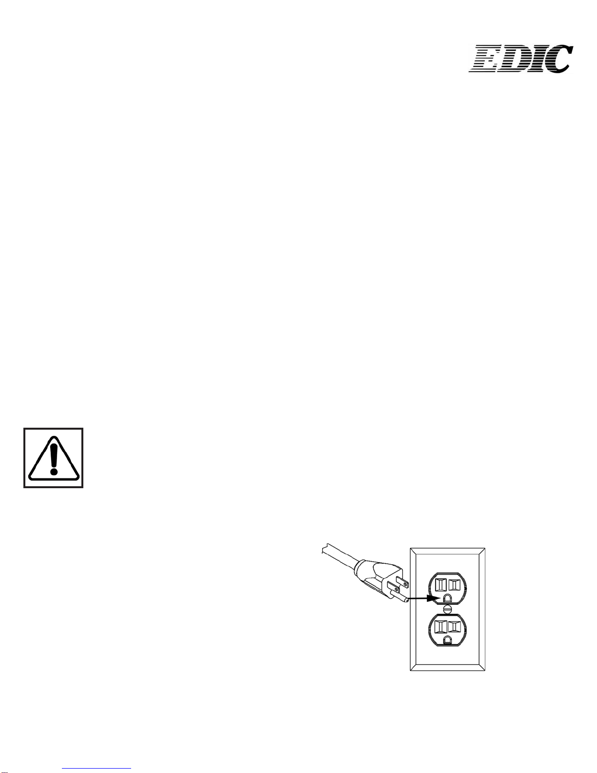
• Make sure the machine is plugged into an electrical
outlet with the same voltage and frequency rating as
shown on the nameplate of the machine. Do not at-
tempt to plug a 115- volt machine into a 230- volt out-
let.
• Do not immerse or use this machine in standing water.
Such use can cause electric shock.
• Keep the electrical supply cord from contacting the ro-
tating brush or drive block.
• Do not expose machine to freezing temperatures.
• To avoid electric shock, do not expose the unit to rain.
Store indoors only.
3

• Connect to a properly grounded outlet only. See
“Grounding Instructions.”
• Turn o all controls before unplugging.
• When using an extension cord, use a 3 conductor
grounding cord, 12 gauge wire or heavier.
• Do not put any object into openings. Do not use with
any opening blocked. Keep free of dust, lint,
• hair and anything that may reduce air ow.
• Do not operate machine in ammable or explosive ar-
eas.
• All servicing of EDIC’s equipment should be per-
formed by a EDIC authorized service center.
• Keep hair, loose clothing, ngers and all parts of body
away from openings and moving parts.
• Use extra care when cleaning near stairs.
• To reduce the risk of re use only commercially avail-
able oor cleaners and waxes intended for machine
application.
• Risk of explosion - Electrical motors and components
can cause an explosion when operated near volatile
materials and vapors. Do not use this machine near
ammable materials such as solvents, thinners, fuels,
grain dust, etc.
ELECTRICAL - 115 Volt
Model: ALL LISTED ON COVER WITHOUT “-220V”
is machine is designed to operate on a standard 15
amp, 120 volt, 60 Hz, AC circuit. Voltages below 105 volt
AC or above 125 volts AC could cause serious damage to
the motor.
ELECTRICAL - 240 Volt
Model: ANY MACHINES WITH A “-220V” AT THE
END OF MODEL NUMBER
is machine is designed to operate on a standard 8.3
amp type L fused 230 volt, 50 Hz, AC circuit. Voltages
below 200 volt AC or above 250 volts AC could cause
serious damage to the motor.
GROUNDING INSTRUCTIONS:
is piece of equipment must be grounded. Should an
electrical malfunction occur, grounding provides a path
of least resistance for electrical current- reducing the risk
of electric shock. is piece of equipment is furnished
with a cord that has a grounding conductor and ground-
ing plug. e grounded plug must only be plugged
into an appropriate outlet that is properly installed and
grounded in accordance with all local codes and ordi-
nances.
WARNING:
Connecting the equipment to an improperly grounded
outlet can result in an increased risk of electric shock. A
qualified electrician should be consulted if you are unsure
that the outlet is properly grounded. Do not modify the
plug provided with the equipment. If it will not fit the
outlet, have a proper outlet installed by a qualified electri-
cian.
is appliance is designed for use on a 120-volt circuit.
e grounding plug provided looks like the plug illustrat-
ed in Figure 1. Replace the power cord if the grounding
pin is damaged or broken.
Extension cords connected to this machine should be 12
gauge, three-wire cords with three-prong plugs and out-
lets. DO NOT use extension cords more than 25 feet
(7.6 m) long
.
4
Figure 1

MAINTENANCE:
is SATURN has been engineered and built to require
minimum maintenance. But like any machine, it does
require some care to keep it in optimum working condi-
tion. Careful attention to these maintenance instructions
will give you maximum operating performance and life
expectancy of the machine.
CAUTION: Disconnect the power cord from the outlet
before doing any clean up or maintenance on the ma-
chine
1. Keep the machine clean. Do not allow dust to accu-
mulate on external surfaces, the motor, or near any
moving parts.
2. Aer every job, wipe down the surface of the ma-
chine with a clean damp cloth.
3. Inspect cord for damage. Do not use machine with a
damaged cord.
CORD STORAGE:
While not in use, storage can be accomplished by wind-
ing cord around handle assy. Cord should be
completely unwound during operation.
CORD SAFETY
• Do not leave appliance when plugged in. Unplug
from outlet when not in use and before servicing
• Do not use with damaged cord or plug. If appliance is
not working as it should, has been dropped, damaged,
le outdoors, or dropped into water, return to service
center for inspection and repair.
• Do not pull or carry by cord, use cord as handle,
close a door on cord, or pull cord around sharp
edges or corners. Do not run this SATURN over the
cord. Keep cord away from heated surfaces.
• Do not unplug by pulling cord. To unplug, grasp the
plug, not the cord.
• Do not handle plug or appliance with wet hands.
• Always unplug the machine when removing brush.
• is equipment should be stored indoors and not
exposed to rain.
CLEAN UP & STORAGE
1. Unplug and wrap it under the cord hook and around
the le side handle grip. Clean the cord and inspect it
for cuts, gashes and loose prongs.
2. Wipe down the machine and store in clean dry place.
WARNING: Do not store the machine with the drive
block, pad driver or brush on the machine.
PAD INSTALLATION:
1. To install pad, tilt the machine back on the rear
wheels until machine is resting on handle.
2. Center the pad on the pad holder and insert pad cen-
ter lock by twisting clockwise. Make sure the center
lock is tight.
To remove: Twist the center lock counterclockwise
MACHINE OPERATION:
is equipment is equipped with a trigger safety inter-
lock. Refer to Diagram 1 for steps 5, 6, and 7.
1. Install the pad driver and pad or attachment.
2. Plug in machine.
3. Adjust the handle to the desired operating position.
4. Lean the machine back, with all four wheels on the
oor, so the pad is not making contact with the oor
when you turn the motor on.
5. Place both hands on the handle grips with your n-
gers around the on/o lever (Refer to B on Diagram
1) Which extends from one side to the other, under-
5
Center
lock

neath the handle grips.
6. e safety “lock-out” lever (Refer to A on Diagram 1)
is located underneath the right side handle grip and
switch lever. To unlock the “lock-out” lever, use your
right hand fore nger to press the lever down toward
the back of the switch box.
7. With trigger safety interlock in the unlocked position,
Pull up on either side of the ON/OFF lever (Refer to
B on Diagram 1) to power the motor. Pull up on only
one side of the ON/OFF lever.
8. Once the motor is at full speed, carefully lower the
pad onto the oor.
TO MANEUVER THE MACHINE
1. Raise the handle slightly and the machine will go to
the right. e higher you raise it, the faster it will go.
2. Lower the handle and the machine will go le. e
more you lower it, the faster it will go.
3. Practice on a smooth surface until you gain experi-
ence in operating the unit.
TO ADJUST THE HANDLE-LOCK
MECHANISM:
1. Unlock the handle and place it in the upright posi-
tion.
2. Tighten the adjusting nut until there is just a slight
drag when the handle is raised or lowered. Do not
overtighten.
3. Place the handle grip into the down (locked) position
to check for proper locking function.
6
TO ADJUST A DRIVE BELT
1. Loosen, but do not remove the 4 bolts, that hold the
motor to the frame.
2. Tighten the 2 screws at the back of the frame until the
belt is tight.
3. Test and re-adjust the belt until the belt does not slip.
Re-tighten the four motor bolts.
WARNING: DO NOT OVER-TIGHTEN THE BELT
SERVICING:
In the event that your SATURN requires service, please
contact EDIC:
800-338-3342
No user serviceable components are employed in this
equipment. Do not attempt repairs yourself. EDIC will
assist you in locating an indepedent service contractor.
B
B
A
Diagram 1
Locking Mechanism
handle
Adjusting nut

B
W
G
B
W
G
BLUE BROWN
LAMP
DC MOTOR
SWITCH
B
W
G
HANDLE MOTOR
7
WIRING FOR ALL
HIGH SPEED
MODELS:

DD11490B-H DRIP COVER W- LIGHT, BLACK
D11490B DRIP COVER, BLACK
MODEL:
17HS2000F-SS
17HS2000F-BK
PART NUMBER FOR 17HS2000F-SS PART NUMBER FOR 17HS2000-BK, IF DIFFERENT
D11485B BRUSHCOVER, BLACK
8

DD11490B-H DRIP COVER W- LIGHT, BLACK
D11490B DRIP COVER, BLACK
MODEL:
17HS2000F-SS
17HS2000F-BK
PART NUMBER FOR 17HS2000F-SS PART NUMBER FOR 17HS2000-BK, IF DIFFERENT
D11485B BRUSHCOVER, BLACK
9
MODEL: 17HS2000F-SS, 17HS2000F-BK
115V, FOR 220V USE G11744

10
12 3 4
56 789
10
11
12
13
14
15
16
17
18 19
20
21
23
24
25
26
27
28
29
31 30
32
33
34
35
36
37
38
39 40
41
42
43
44
45
22
ITEM
NO.
PART NUMBER
DESCRIPTION
QTY.
1
H02548-2 Label, Important, Cord
1
2
B11900 Power Cord, 12-3, 75 FT, SJTW
1
3
K11498 Grip
2
4
C11528 Screw, 10-32 X .25 in
1
5
H12069 Label, 2000 RPM, Saturn
1
6
H11831 Label, EDIC, Black-Silver
1
7
D11496B Switch Box Cover, Black
1
8
H11493 Label, Safety, Floor Machine
1
9
C11529 Screw, 10-32 X .375 in
2
10
K11519 Lever Grip, Lockout, Black
1
11
C00278 Locknut, 10-32, Nylon, SS
1
12
D11494 Lockout Bracket
1
13
D11524 Spring, Lockout
1
14
C90007 Screw, 10-32 X .625 Phillips, Truss Head, SS
1
15
C11491 Screw, 10-32 X 1 in, SS
1
16
C00306 Roll Pin, .125 X 1.75
2
17
D11523 Spring, Trigger
2
18
D11479 Handle, Chrome, Floormachine
1
19
D11495 Trigger, Zinc Plated
1
20
K11520 Lever Grip, Trigger, Black
2
21
11507A Assembled Locking Handle, Cord Hook
1
22
C11619 Allen Wrench, .31 in
1
23
D11497 Handle, Locking Clamp
1
24
C11538 Cap Nut, .31 in, Push-On
1
25
C00259 Washer, Slotted, Zinc
1
26
C11536 Spade Bolt, .375-16 X 4 in
1
27
D11507 Cord Hook Clamp
1
28
D11507-2 Cord Hook Body
1
29
C11558 Locknut, Black Oxide, Thin
2
30
C11502 Socket Cap Screw, .375-16 X 2.5 in
1
31
C11537 Dowel Pin, .31 X 1.5 in
1
32
B10734 Strain Relief, Handle
1
33
B11513 Cord, Handle, 14-3 SJTW
1
34
B11762 Terminal Lug, Nylon, Female
2
35
B11465 Switch, DPST, Pushbutton
1
36
B00177 Terminal Lug, Female, QD, .25 X .032
2
37
C00252 Washer, .375 in, Flat
1
38
C11541 Washer, .375 in, Star
1
39
B11518 Switch Insulation
1
40
C00284 Screw, 10-32 X .375 Ground
1
41
B00187 Cable Clamp, Nylon, .43 in.
1
42
B00180-10-3 Ring Terminal, #10 Center
2
43
B11505 Strain Relief Nut, Metal
1
44
C11560 Washer, .93 ID X 1.5 OD
1
45
B11504 Strain Relief, Metal
1
HANDLE ASSEMBLY
FOR ALL NON FOLD-
ING HIGH SPEED
SATURNS

11
12 3 4
56 789
10
11
12
13
14
15
16
17
18 19
20
21
23
24
25
26
27
28
29
31 30
32
33
34
35
36
37
38
39 40
41
42
43
44
45
22
ITEM
NO.
PART NUMBER
DESCRIPTION
QTY.
1
H02548-2 Label, Important, Cord
1
2
B11900 Power Cord, 12-3, 75 FT, SJTW
1
3
K11498 Grip
2
4
C11528 Screw, 10-32 X .25 in
1
5
H12069 Label, 2000 RPM, Saturn
1
6
H11831 Label, EDIC, Black-Silver
1
7
D11496B Switch Box Cover, Black
1
8
H11493 Label, Safety, Floor Machine
1
9
C11529 Screw, 10-32 X .375 in
2
10
K11519 Lever Grip, Lockout, Black
1
11
C00278 Locknut, 10-32, Nylon, SS
1
12
D11494 Lockout Bracket
1
13
D11524 Spring, Lockout
1
14
C90007 Screw, 10-32 X .625 Phillips, Truss Head, SS
1
15
C11491 Screw, 10-32 X 1 in, SS
1
16
C00306 Roll Pin, .125 X 1.75
2
17
D11523 Spring, Trigger
2
18
D11479 Handle, Chrome, Floormachine
1
19
D11495 Trigger, Zinc Plated
1
20
K11520 Lever Grip, Trigger, Black
2
21
11507A Assembled Locking Handle, Cord Hook
1
22
C11619 Allen Wrench, .31 in
1
23
D11497 Handle, Locking Clamp
1
24
C11538 Cap Nut, .31 in, Push-On
1
25
C00259 Washer, Slotted, Zinc
1
26
C11536 Spade Bolt, .375-16 X 4 in
1
27
D11507 Cord Hook Clamp
1
28
D11507-2 Cord Hook Body
1
29
C11558 Locknut, Black Oxide, Thin
2
30
C11502 Socket Cap Screw, .375-16 X 2.5 in
1
31
C11537 Dowel Pin, .31 X 1.5 in
1
32
B10734 Strain Relief, Handle
1
33
B11513 Cord, Handle, 14-3 SJTW
1
34
B11762 Terminal Lug, Nylon, Female
2
35
B11465 Switch, DPST, Pushbutton
1
36
B00177 Terminal Lug, Female, QD, .25 X .032
2
37
C00252 Washer, .375 in, Flat
1
38
C11541 Washer, .375 in, Star
1
39
B11518 Switch Insulation
1
40
C00284 Screw, 10-32 X .375 Ground
1
41
B00187 Cable Clamp, Nylon, .43 in.
1
42
B00180-10-3 Ring Terminal, #10 Center
2
43
B11505 Strain Relief Nut, Metal
1
44
C11560 Washer, .93 ID X 1.5 OD
1
45
B11504 Strain Relief, Metal
1
HANDLE ASSEMBLY FOR ALL
NON FOLDING HIGH SPEED

12
1
2
3
4
5
6
7
8
9
1211 13
14
16
15
22
19 20 22
23
17
18
24
25
26
27 28 29
30
31 32
33
35
37
34
38
39
41
42
44
45
46
48
47
49
50
51
53
52
54
43
36
37
34
10
40
36
24 25
32
50
ITEM
NO.
PART NUMBER
FOR BLACK MODEL
QTY.
1
B02196-1 Light, Motor Carbon Brush Wear
1
2
C11916 Screw, 10-32 X .375 Phillips
6
3
H11830 Label, Saturn, Drip Cover
1
4
D11490C-H Drip Cover, Chrome w-Hole for Green Light
1
5
C00297 Screw,#8 X .25 in, Pan Head
2
6
D11545 Motor Screen
1
7
C00293 #8 X .5in Pan, Black SMS, Phillips
1
8
B00187 Cable Clamp, Nylon, .43 in.
1
9
G11557 Motor, High Speed
1
10
B00177 Terminal Lug, Female, QD, .25 X .032, 16-14 AWG, Fully Insulated
2
11
D11543 Handle Brace, Left
1
12
H03545 Cover, Serial # Label
1
13
H10976-1 Label, UL STD 561-507
1
14
H00565-5 Label, Serial #, Standard
1
15
C11568 Hex Bolt, .31- 18 X 2.5 in
4
16
D11526 Frame, Motor, Black
1
17
D11563 Axle, Handle
1
18
K00674 Bushing, .50 in, Nylon
4
19
C00261 Nut, .25-20, Hex
6
20
D11542 Tension Adjustment Bracket
2
21
C00233 Washer, Flat, .25 in
2
22
C00319 Hex Tap Bolt, 1-4 X 20 X 3.5 in
2
23
D11544 Handle Brace, Right
1
24
C00252 Washer, .375 in, Flat
6
25
C11569 Hex Tap Bolt, 3-8 X 1.25 in
4
26
K11561 Spacer, .25 lg, Nylon, Natural
14
27
C11559 Washer, .515 X .875 X .032
12
28
G11943 Wheel, 5 in Saturn
4
29
C02305 Cap Nut, .5in Push-on
4
30
C11558 Locknut, .375-16
2
31
D11562 Axle, Wheel
1
32
C11555 Key, Motor, .187 in
2
33
D11532 Pulley
1
34
C11567 Set Screw, .312 in
3
35
K00662-50 Spacer, .5 in
2
36
C00250 Lockwasher, .375, Split
5
37
C11571 Hex Tap Bolt, 3-8 X .75 in
3
38
D11535 Washer, 1.75 in, Steel
1
39
E11478 Bumper, 20 in Floor Machine
1
40
F11988 Pad, Hi Speed, 20 in
1
41
2004BR Pad holder, 20 in, High Speed
1
42
C00262 Nut, .31-18, Hex
4
43
C00251 Lockwasher, .31, Split
4
44
D11565 Bearing Plate, Lower
1
45
D11486-SS Brush Cover, 20 in, Stainless
1
46
K11521 Spacer, Base, Floor Machine
4
47
G11531 Bearing
2
48
D11533 Pulley, 3.125 in w- Grooves
1
49
L11530 Belt
1
50
C11556 Wave Washer
2
51
D11534 Shaft, 4.11 in
1
52
D11566 Bearing Plate, Upper
1
53
C11574 Retaining Ring
1
54
D11490C Drip Cover, Chrome
1
D11490B-H BLACK
D11490B DRIP COVER, BK
D11486B BRUSH COVER
BASE ASSEMBLY FOR:
20HS2000-SS
20HS2000-BK

13
1
2
3
4
5
6
7
8
9
1211 13
14
16
15
22
19 20 22
23
17
18
24
25
26
27 28 29
30
31 32
33
35
37
34
38
39
41
42
44
45
46
48
47
49
50
51
53
52
54
43
36
37
34
10
40
36
24 25
32
50
ITEM
NO.
PART NUMBER
FOR BLACK MODEL
QTY.
1
B02196-1 Light, Motor Carbon Brush Wear
1
2
C11916 Screw, 10-32 X .375 Phillips
6
3
H11830 Label, Saturn, Drip Cover
1
4
D11490C-H Drip Cover, Chrome w-Hole for Green Light
1
5
C00297 Screw,#8 X .25 in, Pan Head
2
6
D11545 Motor Screen
1
7
C00293 #8 X .5in Pan, Black SMS, Phillips
1
8
B00187 Cable Clamp, Nylon, .43 in.
1
9
G11557 Motor, High Speed
1
10
B00177 Terminal Lug, Female, QD, .25 X .032, 16-14 AWG, Fully Insulated
2
11
D11543 Handle Brace, Left
1
12
H03545 Cover, Serial # Label
1
13
H10976-1 Label, UL STD 561-507
1
14
H00565-5 Label, Serial #, Standard
1
15
C11568 Hex Bolt, .31- 18 X 2.5 in
4
16
D11526 Frame, Motor, Black
1
17
D11563 Axle, Handle
1
18
K00674 Bushing, .50 in, Nylon
4
19
C00261 Nut, .25-20, Hex
6
20
D11542 Tension Adjustment Bracket
2
21
C00233 Washer, Flat, .25 in
2
22
C00319 Hex Tap Bolt, 1-4 X 20 X 3.5 in
2
23
D11544 Handle Brace, Right
1
24
C00252 Washer, .375 in, Flat
6
25
C11569 Hex Tap Bolt, 3-8 X 1.25 in
4
26
K11561 Spacer, .25 lg, Nylon, Natural
14
27
C11559 Washer, .515 X .875 X .032
12
28
G11943 Wheel, 5 in Saturn
4
29
C02305 Cap Nut, .5in Push-on
4
30
C11558 Locknut, .375-16
2
31
D11562 Axle, Wheel
1
32
C11555 Key, Motor, .187 in
2
33
D11532 Pulley
1
34
C11567 Set Screw, .312 in
3
35
K00662-50 Spacer, .5 in
2
36
C00250 Lockwasher, .375, Split
5
37
C11571 Hex Tap Bolt, 3-8 X .75 in
3
38
D11535 Washer, 1.75 in, Steel
1
39
E11478 Bumper, 20 in Floor Machine
1
40
F11988 Pad, Hi Speed, 20 in
1
41
2004BR Pad holder, 20 in, High Speed
1
42
C00262 Nut, .31-18, Hex
4
43
C00251 Lockwasher, .31, Split
4
44
D11565 Bearing Plate, Lower
1
45
D11486-SS Brush Cover, 20 in, Stainless
1
46
K11521 Spacer, Base, Floor Machine
4
47
G11531 Bearing
2
48
D11533 Pulley, 3.125 in w- Grooves
1
49
L11530 Belt
1
50
C11556 Wave Washer
2
51
D11534 Shaft, 4.11 in
1
52
D11566 Bearing Plate, Upper
1
53
C11574 Retaining Ring
1
54
D11490C Drip Cover, Chrome
1
D11490B-H BLACK
D11490B DRIP COVER, BK
D11486B BRUSH COVER
BASE ASSEMBLY FOR:
20HS2000-SS
20HS2000-BK
115V, FOR 220V USE G11744

14
1
2
3
4
5
6
7
8
9
1211 13
14
16
15
22
19 20 22
23
17
18
24
25
26
27 28 29
30
31 32
33
35
37
34
38
39
41
42
44
45
46
48
47
49
50
51
53
52
54
43
36
37
34
10
40
36
24 25
32
50
ITEM
NO.
PART NUMBER
FOR BLACK MODEL
QTY.
1
B02196-1 Light, Motor Carbon Brush Wear
1
2
C11916 Screw, 10-32 X .375 Phillips
6
3
H11830 Label, Saturn, Drip Cover
1
4
D11490C-H Drip Cover, Chrome w-Hole for Green Light
1
5
C00297 Screw,#8 X .25 in, Pan Head
2
6
D11545 Motor Screen
1
7
C00293 #8 X .5in Pan, Black SMS, Phillips
1
8
B00187 Cable Clamp, Nylon, .43 in.
1
9
G11557 Motor, High Speed
1
10
B00177 Terminal Lug, Female, QD, .25 X .032, 16-14 AWG, Fully Insulated
2
11
D11543 Handle Brace, Left
1
12
H03545 Cover, Serial # Label
1
13
H10976-1 Label, UL STD 561-507
1
14
H00565-5 Label, Serial #, Standard
1
15
C11568 Hex Bolt, .31- 18 X 2.5 in
4
16
D11526 Frame, Motor, Black
1
17
D11563 Axle, Handle
1
18
K00674 Bushing, .50 in, Nylon
4
19
C00261 Nut, .25-20, Hex
6
20
D11542 Tension Adjustment Bracket
2
21
C00233 Washer, Flat, .25 in
2
22
C00319 Hex Tap Bolt, 1-4 X 20 X 3.5 in
2
23
D11544 Handle Brace, Right
1
24
C00252 Washer, .375 in, Flat
6
25
C11569 Hex Tap Bolt, 3-8 X 1.25 in
4
26
K11561 Spacer, .25 lg, Nylon, Natural
14
27
C11559 Washer, .515 X .875 X .032
12
28
G11943 Wheel, 5 in Saturn
4
29
C02305 Cap Nut, .5in Push-on
4
30
C11558 Locknut, .375-16
2
31
D11562 Axle, Wheel
1
32
C11555 Key, Motor, .187 in
2
33
D11532 Pulley
1
34
C11567 Set Screw, .312 in
3
35
K00662-50 Spacer, .5 in
2
36
C00250 Lockwasher, .375, Split
5
37
C11571 Hex Tap Bolt, 3-8 X .75 in
3
38
D11535 Washer, 1.75 in, Steel
1
39
E11478 Bumper, 20 in Floor Machine
1
40
F11988 Pad, Hi Speed, 20 in
1
41
2004BR Pad holder, 20 in, High Speed
1
42
C00262 Nut, .31-18, Hex
4
43
C00251 Lockwasher, .31, Split
4
44
D11565 Bearing Plate, Lower
1
45
D11486-SS Brush Cover, 20 in, Stainless
1
46
K11521 Spacer, Base, Floor Machine
4
47
G11531 Bearing
2
48
D11533 Pulley, 3.125 in w- Grooves
1
49
L11530 Belt
1
50
C11556 Wave Washer
2
51
D11534 Shaft, 4.11 in
1
52
D11566 Bearing Plate, Upper
1
53
C11574 Retaining Ring
1
54
D11490C Drip Cover, Chrome
1
D11490B-H BLACK
D11490B DRIP COVER, BK
D11486B BRUSH COVER
BASE ASSEMBLY FOR:
20HS1500-SS
20HS1500-BK

15
1
2
3
4
5
6
7
8
9
1211 13
14
16
15
22
19 20 22
23
17
18
24
25
26
27 28 29
30
31 32
33
35
37
34
38
39
41
42
44
45
46
48
47
49
50
51
53
52
54
43
36
37
34
10
40
36
24 25
32
50
ITEM
NO.
PART NUMBER
FOR BLACK MODEL
QTY.
1
B02196-1 Light, Motor Carbon Brush Wear
1
2
C11916 Screw, 10-32 X .375 Phillips
6
3
H11830 Label, Saturn, Drip Cover
1
4
D11490C-H Drip Cover, Chrome w-Hole for Green Light
1
5
C00297 Screw,#8 X .25 in, Pan Head
2
6
D11545 Motor Screen
1
7
C00293 #8 X .5in Pan, Black SMS, Phillips
1
8
B00187 Cable Clamp, Nylon, .43 in.
1
9
G11557 Motor, High Speed
1
10
B00177 Terminal Lug, Female, QD, .25 X .032, 16-14 AWG, Fully Insulated
2
11
D11543 Handle Brace, Left
1
12
H03545 Cover, Serial # Label
1
13
H10976-1 Label, UL STD 561-507
1
14
H00565-5 Label, Serial #, Standard
1
15
C11568 Hex Bolt, .31- 18 X 2.5 in
4
16
D11526 Frame, Motor, Black
1
17
D11563 Axle, Handle
1
18
K00674 Bushing, .50 in, Nylon
4
19
C00261 Nut, .25-20, Hex
6
20
D11542 Tension Adjustment Bracket
2
21
C00233 Washer, Flat, .25 in
2
22
C00319 Hex Tap Bolt, 1-4 X 20 X 3.5 in
2
23
D11544 Handle Brace, Right
1
24
C00252 Washer, .375 in, Flat
6
25
C11569 Hex Tap Bolt, 3-8 X 1.25 in
4
26
K11561 Spacer, .25 lg, Nylon, Natural
14
27
C11559 Washer, .515 X .875 X .032
12
28
G11943 Wheel, 5 in Saturn
4
29
C02305 Cap Nut, .5in Push-on
4
30
C11558 Locknut, .375-16
2
31
D11562 Axle, Wheel
1
32
C11555 Key, Motor, .187 in
2
33
D11532 Pulley
1
34
C11567 Set Screw, .312 in
3
35
K00662-50 Spacer, .5 in
2
36
C00250 Lockwasher, .375, Split
5
37
C11571 Hex Tap Bolt, 3-8 X .75 in
3
38
D11535 Washer, 1.75 in, Steel
1
39
E11478 Bumper, 20 in Floor Machine
1
40
F11988 Pad, Hi Speed, 20 in
1
41
2004BR Pad holder, 20 in, High Speed
1
42
C00262 Nut, .31-18, Hex
4
43
C00251 Lockwasher, .31, Split
4
44
D11565 Bearing Plate, Lower
1
45
D11486-SS Brush Cover, 20 in, Stainless
1
46
K11521 Spacer, Base, Floor Machine
4
47
G11531 Bearing
2
48
D11533 Pulley, 3.125 in w- Grooves
1
49
L11530 Belt
1
50
C11556 Wave Washer
2
51
D11534 Shaft, 4.11 in
1
52
D11566 Bearing Plate, Upper
1
53
C11574 Retaining Ring
1
54
D11490C Drip Cover, Chrome
1
D11490B-H BLACK
D11490B DRIP COVER, BK
D11486B BRUSH COVER
BASE ASSEMBLY FOR:
20HS2000-SS
20HS2000-BK
115V, FOR 220V USE G11744
This manual suits for next models
5
Table of contents
Other Saturn Floor Machine manuals