Sauer Danfoss 51 Series User manual

GROUP 3025HYDRAULIC PUMP
3025--9A, Page 1
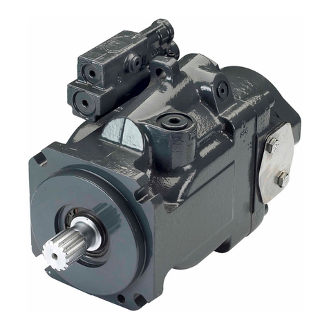
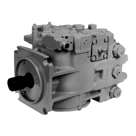
SAUER DANFOSS SERIES 51 BENT AXIS HYDRAULIC MOTOR
1 INTRODUCTION. 2.............................................................................
1.1 Specification Sheet 3......................................................................
2 GENERAL DESCRIPTION. 4....................................................................
3 TEST GAUGE INSTALLATION 6.................................................................
4 START--UP PROCEDURE 7.....................................................................
5 CHANGING THE FLUID AND FILTER 7...........................................................
6 COMPONENT ADJUSTMENTS 8................................................................
6.1 Charge Pressure Relief Valve Adjustment 8..................................................
6.2 Minimum Displacement Limiter Adjustment. 9.................................................
6.3 Maximum Displacement Limiter Adjustment. 10...............................................
6.4 Displacement Control Adjustments. 11.......................................................
6.5 Minor Repair and Replacement. 12..........................................................
6.5.1 General 12.......................................................................
6.5.2 Shaft Seal Replacement 13.........................................................
6.5.3 Loop Flushing Shuttle Valve Replacement 15..........................................
6.5.4 Charge Pressure Relief Valve Replacement 16........................................
6.5.5 Minimum Angle Servo Cover Replacement 17.........................................
6.5.6 Electrohydraulic Proportional Control Service (Type EQ) 18.............................
6.5.7 Pressure Control Pilot Valve 21......................................................
6.5.8 Multi--Function Block Removal and Installation 22......................................
6.5.9 Servo Pressure Supply Shuttle Spool 23..............................................
6.5.10 PCOR Brake Pressure Defeat Spool 24..............................................
6.5.11 Control Orifices 26.................................................................
6.6 Torque Values. 27.........................................................................
7 TROUBLESHOOTING 28........................................................................

GROUP 3025 HYDRAULIC PUMP
3025--9A, Page 2
1 INTRODUCTION.
This group provides information for servicing the Series
51 bent axis variable displacement hydralic motor used
to power the auger on H Series High Speed Blowers.
An exploded view with component description,
troubleshooting procedures, adjustments and minor
repairs are covered in this group.
Many repairs and adjustments can be performed with
the Series 51 motor mounted to the gear reduction unit
on the blower, if the motor is throughly cleaned before
beginning any procedures.
Dirt or contamination is the greatest enemy of any type
of hydraulic equipment. The greatest possible
cleanliness is necessary when starting up the system,
changing filters, or performing any other service
procedure.

GROUP 3025HYDRAULIC PUMP
3025--9A, Page 3
Series 51 Motor Specification Sheet
Model Code: 51V 080 R S1 N EQ A2 K Y G0 NNN 030 AA E4 85 31
51 = Series 51 Bent Axis Motor
V = SAE Flange Mount
080 = 80cc/rev (4.92 cu in/rev) Maximum Displacement
R = Side Ports
S1 = 14 tooth 12/24 Pith Spline Shaft
N = No Maximum Displacement Limiter
EQ = Electric Displacement Control MS Connector
A2 = Internal EDC Supply and PCOR
K = 50 to 85 mA Threshold Current Range
Y = 70 mA Control Ramp Range
G0 = Standard Control for Internal Supply
NNN = No special hardware features
030 = 30 cc/rev (1.83 cu in/rev) Minimum Displacement
AA = No High Pressure Reliefs
E4 = 1.1 GPM Loop Flushing Flow
85 = 85 mA Threshold Current Setting
31 = 310 Pressure Compensator Setting

GROUP 3025 HYDRAULIC PUMP
3025--9A, Page 4
2 GENERAL DESCRIPTION
The Series 51 variable displacement hydraulic motor
uses spherical pistons and piston rings. The angle
between the cylinder block and the output shaft can be
set between 32oand 6o, providing a 5 to 1 maximum to
minimum displacement ratio.
At maximum displacement, the motor will provide a
certain maximum ouput shaft torque and minimum
speed corresponding to the pressure and flow supplied
to the motor. Under the same input conditions but at
minimum displacement, the shaft speed will be
approximately one--fifth the full displacement value.
The displacement is changed by a servo piston which is
connected to the valve segment.
An electrohydraulic control is mounted on the motor end
cap to control the servo piston and the motor
displacement. Servo pressure oil is supplied externally
from the hydraulic reservoir pump.
A synchronizing shaft, with spherical rollers,
synchronizes the rotation of the output shaft and the
cylinder block. The ball end of each piston runs in a
socket bushing pressed into the output shaft. There are
no other parts used to connect the pistons to the shaft.
Two tapered roller bearings support the output shaft.
Charge Pressure
Relief Valve
Servo Piston
Cylinder
Control
Pressure
Port
Hydraulic
Proportional
Control
Piston Synchronizing Shaft
Tapered Roller Bearings
Bearing Plate
Minimum Displacement Limiter
Valve Segment
Pressure
Compensator
Override
Figure 1. Sectional View of Series 51 with Hydraulic Proportional Control

GROUP 3025HYDRAULIC PUMP
3025--9A, Page 5
Type EQ electrohydraulic proportional control (Fig. 2)
consists of a valve block and pressure control pilot
(PCP) valve mounted on the multi--function block. The
valve block incorporates a pilot piston with centering
springs. A pin transmits force from the pilot piston to the
control spool in the end cap. Feedback springs and a
threshold spring are installed in the end cap. These
springs function similar to the HS control. Servo
pressure may be supplied from an external source or
internally by the shuttle spool in the multi--function block.
An external pilot pressure source is connected to the
inlet of the PCP valve, which produces differential pilot
pressures proportional to the current through it. These
pressures are applied to the pilot piston. The operation
of this control is similar to that of the HP Control, with the
motor displacement being proportional to the current
through the PCP valve. An increase in current above
the threshold current will result in a decrease in motor
displacement, while a decrease in current will result in
an increase in displacement.
Figure 2. EQ Control Components

GROUP 3025 HYDRAULIC PUMP
3025--9A, Page 6
3 TEST GAUGE INSTALLATION
Pressure gauge readings can be used in
troubleshooting problems with Series 51 motor or
system problems. Figure 3 details port location.
M3 Gauge Port
M5 Gauge Port
M1 Gauge Port
M2 Gauge Port
Figure 3. EQ Model Control Gauge Port locations.
Port Designation & Type
Port Use Type
A & B Main Pressure Lines Split Flange
L1, L2 Drain Lines O--Ring
M1, M2 Gauge Ports for A & B
M3, M4 Gauge Port -- Servo Pressure
O--Ring
O--Ring
M5 Gauge Port -- Servo Supply
Port for External Supply
O--Ring
X1 O--Ring

GROUP 3025HYDRAULIC PUMP
3025--9A, Page 7
4 START---UP PROCEDURE
The start--up procedure must be followed when starting
up a new Series 51 installation or when restarting an
installation in which either the pump or motor has been
removed from the system.
WARNING
It is recommended that the auger be
disconnected from the torque hubs
while performing the start--up pro-
cedure to prevent possible injury to
the technician or bystanders. If the
auger has already been installed in
the housing before start--up of the
Series 51 hydraulic motor is at-
tempted, disconnect the auger from
thetorquehubs,supporttheauger
with a lift fixture and remove the
spacers from each hub/auger junc-
tion. Refer to group 3001--7 High
Speed Blower.
Fill the vehicle hydraulic reservoir with the
recommended hydraulic fluid passing the fluid through a
10 micron filter. Disconnect the outlet line from the
hydraulic pump at the reservoir and fill this line and the
inlet line to the Series 51 motor with hydraulic fluid.
Fill the pump and motor housing with clean hydraulic
fluid by pouring filtered oil into the upper case drain port.
Install a 0 to 60 bar or 0 -- 1000 psi pressure gauge in the
charge pressure gauge port (M1 or M2, refer to Fig. 3) to
monitor the charge pressure during start--up.
The electrical connector should be disconnected at the
pump control during initial start--up. This will allow the
pump to remain in the neutral position.
Slowly rotate the torque hub by hand, or “jog” the pump
until charge pressure starts to rise. Start the Series 51
pump and run at the lowest possible RPM until charge
pressure is established. Bleed excess air from the high
pressure lines through the high pressure gauge ports.
Once charge pressure is established, increase speed to
normal operating RPM. Note the charge pressure. If
charge pressure is incorrect, shut down and determine
cause for improper pressure.
Shut down the blower engine and reconnect electrical
connector at electrohydraulic control. Start the Series
51 pump, checking to be certain pump remains in
neutral. With prime mover at normal operating speed,
slowly check for forward and reverse machine
operation.
Charge pressure should be maintained during forward
or reverse operation. Continue to cycle slowly between
forward and reverse for at least five minutes. Shut down
the pump, remove gauges and plug ports. Check
hydraulic reservoir level and add fluid if necessary.
Reconnect auger to torque hubs if removed.
5 CHANGING THE FLUID AND FILTER
The reservoir breather/air filter must be kept clean.
Clean the area around the filler cap before opening the
reservoir. The hydraulic fluid must be filtered through a
10 micron filter before it enters the reservoir.
The fluid and filter must be changed at the following
intervals:
DSystem with a breathing type reservoir --- 500 hrs
It may be necessary to change the fluid more frequently
if the fluid becomes contaminated with foreign matter
(dirt, water, grease, etc.) or if the fluid has been
operating at temperature levels greater than the
maximum recommended. Never reuse fluid.
Change the filter every time the fluid is changed, or on a
more frequent basis if the filter indicator indicates a
change is necessary.
GROUP 3025 HYDRAULIC PUMP
3025--9A, Page 8
6 COMPONENT ADJUSTMENTS
WARNING
It is recommended that the auger be
disconnected from the torque hubs
while performing pump adjust-
ments to prevent possible injury to
the technician or bystanders. Dis-
connect the auger from the torque
hubs, support the auger with a lift
fixture and remove the spacers from
each hub/auger junction. Refer to
group 3001--7 High Speed Blower.
6.1 Charge Pressure Relief Valve Adjustment
Correct charge pressure must be maintained under all
conditions of operation to maintain pump control per-
formance in closed loop systems.
To measure and adjust motor charge pressure:
(1) Install a 0 to 60 bar or 0 to 1000 psi pressure
gauge in the motor charge pressure gauge
port. Install a gauge to measure case pres-
sure.
(2) Operate the system with the motor at normal
operating speed and the pump at half stroke
(forward or reverse) when measuring motor
charge pressure.
(3) In most applications the motor charge relief
valve is set to 2 to 4 bar (29 to 58 psi) below
the setting of the pump charge relief valve
(measured with the pump in the “neutral” or
zero---angle position). This setting assumes
a reservoir temperature of 50oC (122oF),
and is referenced to case pressure.
(4) Adjust the charge pressure by loosening the
locknut with a 1---1/16” wrench and turning
the adjustment plug with a large screwdriver
(Fig. 4). Clockwise rotation of the plug in-
creases the setting, and counterclockwise
rotation decreases the setting at a rate of
approximately 3.4 bar (50 psi) per turn.
Figure 4. Charge Pressure Relief Adjustment
(5) Once the desired pressure is reached, re-
tighten the locknut to 38 ft. lbs. (52 Nm), re-
move the gauges and reinstall the port
plugs.

GROUP 3025HYDRAULIC PUMP
3025--9A, Page 9
6.2 Minimum Displacement Limiter Adjustment
WARNING
Care should be taken in adjusting
displacement limiters to avoid un-
desirable speed conditions. The
sealing lock nut must be retorqued
after every adjustment to prevent an
unexpected change in operating
conditions and to prevent external
leakage during unit operation.
NOTE
The Series 51 motor supplied on the
H--Series High Speed blower is de-
livered with the minimum displace-
ment set at 30cc/rev (1.83 cu in/rev).
To adjust minimum displacement, remove and discard
the adjusting screw cap and adjust as follows:
(1) Use a 17 mm wrench to loosen the lock nut
retaining the minimum displacement limiter
screw (Fig. 5).
Figure 5. Minimum Displacement Limiter Lock Nut
(2) Use a 5 mm internal hex wrench to rotate the
the adjusting screw to change the minimum
displacement (Fig. 6). Rotate the adjusting
screw clockwise to increase the minimum
displacement, or rotate the adjusting screw
counterclockwise to decrease the minimum
displacement of the motor.
Figure 6. Minimum Displacement Adjusting Screw
(3) Each full revolution of the adjusting screw
changes the displacement 2.1 cc. Different
minimum displacements may require differ-
ent length adjusting screws. Refer to Table
1.
Table 1. Alternate Displacement Screws
Min. Displacement
Range cc/Rev
Screw Size and
Length mm (in)
16 to 35
36 to 54
M10x 65 (2.56)
M10 x 80 (3.15)
(4) After establishing the desired minimum dis-
placement setting, tighten the locknut on
the adjusting screw to 38 ft. lbs. (51 Nm).
Install a new tamper---resistant cap on the
adjusting screw.

GROUP 3025 HYDRAULIC PUMP
3025--9A, Page 10
6.3 Maximum Displacement Limiter Adjustment
WARNING
Care should be taken in adjusting
displacement limiters to avoid un-
desirable speed conditions. The
stop screw must be retorqued after
adjustment to prevent an unex-
pected change in operating condi-
tions.
NOTE
The Series 51 motor supplied on the
H--Series High Speed blower is de-
livered with the maximum displace-
ment set at 80cc/rev (4.92 cu in/rev).
The maximum displacement of the motors can be
limited by limiting the stroke of the setting piston, and the
resulting movement of the valve segment. A
displacement limiter screw is installed on the setting
piston (under minimum angle servo cover) to limit the
stroke of the piston. Spacers may be installed on the
displacement stop screw to limit the stroke. A longer or
shorter screw must be used to retain a thicker or thinner
spacer.
To adjust the maximum displacement:
(1) Remove the screws retaining the the mini-
mum angle servo cover to the end cap with
an 8 mm internal hex wrench (Fig. 7).
Figure 7. Minimum Angle Servo Cover Removal
(2) Remove the minimum angle servo cover
and o---rings. Remove the displacement
limiter screw with an 8 mm internal hex
wrench (Fig. 8)
Figure 8. Displacement Limiter Screw Removal
(3) Installing a thicker spacer on the end of the
Displacement limiter screw will reduce the
maximum displacement of the motor. Instal-
ling a thinner spacer will increase the maxi-
mum displacement. The displacement will
change 1.14 cc per mm of spacer thickness.
(4) Torque the displacement limiter screw to 40
ft. lbs (54 Nm) when reinstalling in motor
body.
(5) Install the minimum angle servo cover and
itso---ringstorquingthecoverscrewsto58
ft. lbs (78 Nm).
(6) Remove the minimum angle servo cover
and o---rings. Remove the displacement
limiter screw with an 8 mm internal hex
wrench (Fig. 8)

GROUP 3025HYDRAULIC PUMP
3025--9A, Page 11
6.4 Displacement Control Adjustments:
Electro--hydraulic Proportional Control Type EQ
NOTE
A change in motor displacement
can be detected by providing a
constant flow of fluid to the motor
and monitoring the motor output
shaft speed while adjusting the con-
trol. Anincreaseindisplacement
will result in a decrease in shaft
speed, while a decrease in displace-
ment will result in an increase in
shaft speed.
The control start current for the EQ controls is adjusted
with the adjusting screw on the end cap (opposite the
control block). Refer to Figure 9. Control start is the
current supplied to the PCP (Pressure Control Pilot)
valve at the point which the motor displacement starts to
decrease.
Figure 9. EQ Type Control
To check the threshold setting:
(1) Install a test meter to monitor the PCP cur-
rent, and a pressure gauge to monitor the
minimum angle servo pressure (port M3).
(2) Increase the control start current. An in-
crease in minimum angle servo pressure will
be noted as the motor displacement starts
to decrease.
(3) Adjust the control start current by loosening
the lock nut using a 10 mm hex wrench and
turning the adjusting screw with a 4 mm in-
ternal hex wrench (Fig. 10). Turning the
screw clockwise increases the control start
current. Torque the locknut to 6.6 ft. lbs (9
Nm) after completing the adjustment.
Figure 10. Adjusting Control Threshold
NOTE
PCP supply pressure oil is provided
externally. PCP supply pressure
must be a minimum of 20 bar (290
psi) and no more than 70 bar (1015
psi). If servo pressure supply oil is
provided externally, a minimum of
25 bar (360 psi) is required to
change the motor displacement
with the motor shaft turning, and a
minimum of 70 bar (1015 psi) is re-
quired with the motor shaft locked.

GROUP 3025 HYDRAULIC PUMP
3025--9A, Page 12
6.5 Minor Repair and Replacement
6.5.1 General
Cleanliness is a primary means of insuring satisfactory
motor life, on either new or repaired units. Cleaning
parts using a solvent wash and air drying is adequate.
As with any precision equipment, the internal
mechanism and related items must be kept free of
foreign material and chemicals.
It is recommended that all gaskets and o--rings be
replaced. All gasket sealing surfaces must be cleaned
prior to installing new gaskets. Lightly lubricate all
o--rings with clean petroleum jelly prior to assembly.

GROUP 3025HYDRAULIC PUMP
3025--9A, Page 13
6.5.2 Shaft Seal Replacement (SAE Flange
Configuration)
Replacement of the lip type shaft seals requires removal
of the Type 51 motor from the torque hub unit. Refer to
Groups 3059 and 3001 for removal information.
(1) Remove the screws holding the flange to the
housing using a 6 mm internal hex wrench
(Fig 11).
Figure 11. Flange to Housing Screw Removal
(2) Remove the flange from the housing using a
two leg puller as shown in Fig 12. Take care
not to damage the housing bore or shaft
whileusingthepuller.
Figure 12. Flange Removal
CAUTION
Do not allow the output shaft to
move out of the housing while re-
moving the flange. After the flange
is removed, do not attempt to re-
move the shaft from the housing. If
the output shaft moves out of the
housing, the synchronizing shaft
and rollers could fall out of position,
requiring major disassembly of the
unit.
(3) Pry the old seal from the flange using a flat
blade screwdriver as shown in Fig. 13. The
seal is not reusable. Inspect the flange for
any damage or nicks.

GROUP 3025 HYDRAULIC PUMP
3025--9A, Page 14
Figure 13. Removal of Seal from Flange
(4) Coat the outside diameter of the seal with a
sealant such as Loctite High Performance
Sealant #59231 prior to installation. This will
aid in preventing leaks caused by damage
to the seal bore in the flange. Press the new
seal into the flange with an arbor press and a
suitable driver (Fig. 14).
Figure 14. Seal Installation
(5) Inspect the sealing area on the shaft for rust,
wear or contamination. Clean or burnish as
necessary.
(6) Install a new o---ring on the flange. Lubricate
the flange o---ring and the inner diameter of
the seal with petroleum jelly.
(7) Wrap the spline or key end of the shaft with
plastic film to prevent damaging the new
seal during installation.
(8) Slide the flange and seal assembly over the
shaft and down into the housing bore.
Install four of the flange screws and tighten
them evenly to pull the flange into position
(Fig. 15). Remove the plastic film from
splines.
Figure 15. Flange Installation on Housing
(9) Install the remaining flange screws and
torque evenly to 24 ft. lbs (32 Nm) (Fig 16).
Figure 16. Torque Flange Screws

GROUP 3025HYDRAULIC PUMP
3025--9A, Page 15
6.5.3 Loop Flushing Shuttle Valve Replacement
(1) Remove the hex plugs from both sides of the
end cap (Fig. 17).
Figure 17. Shuttle Valve Plug Removal
(2) Remove springs and spring seats. Note the
orientation of the washers. Remove flushing
valve spool (Fig.18).
Figure 18. Flushing Valave Spool Removal
(3) Inspect parts (Fig. 19) for damage or foreign
material, clean or replace as necessary.
Figure 19. Loop Flushing Shuttle Valve Components
(4) Install flushing valve spool in end cap (Fig.
20). Install the spring seat washers on each
end of the spool. The step on the spring seat
washers should face out toward the springs.
Figure 20. Valve Spool and Washer Installation
(5) Install the spool springs and hex plugs in
both sides of end cap (Fig. 21). Torque the
plugsto30ft.lbs(41Nm).
Figure 21. Plug and Spring Installation

GROUP 3025 HYDRAULIC PUMP
3025--9A, Page 16
6.5.4 Charge Pressure Relief Valve
Replacement
NOTE
Before removing the screw adjust-
able relief valve plug, it is recom-
mended that you mark the plug, lock
nut and end cap to allow the original
adjustment to be maintained upon
reassembly.
(1) Loosen the locknut with a 1---1/16” hex
wrench and remove the plug with a large
screwdriver (Fig. 22).
Figure 22. Plug Removal
(2) Remove the spring and charge relief valve
poppet (Fig. 23).
Figure 23. Poppet Removal
(3) Inspect the poppet (Fig. 24) and the mating
seat in the plug for damage or foreign mate-
rial. Clean or replace as necessary.
Plug Spring Poppet
Figure 24. Poppet Assembly
(4) Install the poppet and spring in the plug.
Install the plug with its locknut, aligning the
marks made at disassembly and torque the
lock nut to 38 ft. lbs (52 Nm).
(5) Check the charge pressure and adjust if
necessary.

GROUP 3025HYDRAULIC PUMP
3025--9A, Page 17
6.5.5 Minimum Angle Servo Cover Replacement
CAUTION
Before removing the cover, through-
ly clean the external surfaces of the
servo cover and the surrounding
area on the motor to prevent con-
tamination.
(1) Remove the four screws retaining the servo
cover to the end cap using an 8 mm internal
hex wrench (Fig. 25).
Figure 25. Servo Cover Removal
(2) Remove the o---rings between the cover and
end cap and discard.
(3) Coat new o---rings with petroleum jelly and
install on the end cap. Install the cover onto
the end cap torquing to 58 ft. lbs. (78 Nm).
Refer to Figure 26.
Figure 26. Servo Cover Installation

GROUP 3025 HYDRAULIC PUMP
3025--9A, Page 18
6.5.6 Electrohydraulic Proportional Control
(Type EQ) Service
(1) Remove the Pressure Control Pilot (PCP)
valve (Fig. 27) as detailed in paragraph
6.5.7.
Figure 27. PCP Valve Removal
(2) Remove the screws holding the the control
housing cover and control valve housing to
the multi---function block with a 4 mm inter-
nal hex wrench (Fig. 28).
Figure 28. EQ Control Housing Screw Removal
(3) Remove the housing cover and gasket (Fig.
29).
Figure 29. EQ Control Housing Removal
(4) Remove the valve housing with the pilot pis-
ton from the multi---function block.
(5) Remove the o---rings from the valve hous-
ing. Remove the pilot and spring from the
valve housing.
(6) Remove the pilot piston pin from the multi---
function block (Fig. 30).
NOTE
If required, the plugs in the control
housing can be removed with a 1/4”
internal hex wrench. When reinstal-
ling the plugs they must be torqued
to 15 ft.lbs. (20 Nm).
Figure 30. Pilot Piston Pin Removal
(7) Coat new o---rings with petroleum jelly and
install on the valve housing.

GROUP 3025HYDRAULIC PUMP
3025--9A, Page 19
(8) Install the pilot piston pin in the multi---func-
tion block (Fig. 31).
Figure 31. Pilot Pin Installation
(9) Position the valve housing (with o---rings
installed) on the multi---function block (Fig.
32).
Figure 32. Control Housing Installation
(10) Install the pilot piston into the housing and
over the pin. The end of the piston with the
cross drilled hole should engage the pin
(Fig. 33).
Figure 33. Pilot Piston Installation
(11) Install the small spring in the outer end of the
pilot piston (Fig. 34).
Figure 34. Pilot Piston Spring Installation
(12) Install the control cover and gasket. Align
the control assembly with the multi---func-
tion block and install the four screws (Fig.
35). Torque the control screws to 4.7 ft.lbs.
(6.4 Nm).

GROUP 3025 HYDRAULIC PUMP
3025--9A, Page 20
Figure 35. Control Cover Installation
(13) Install the PCP valve (Fig. 36). Torque the
fourscrewsto48in.lbs.(54Nm).
Figure 36. Install PCP Valve
Other manuals for 51 Series
1
This manual suits for next models
1
Table of contents
Other Sauer Danfoss Water Pump manuals

Sauer Danfoss
Sauer Danfoss 40 Series Manual

Sauer Danfoss
Sauer Danfoss H1 Manual

Sauer Danfoss
Sauer Danfoss 20 Series User manual

Sauer Danfoss
Sauer Danfoss Series S90 180 cc Guide

Sauer Danfoss
Sauer Danfoss 45 Series User manual

Sauer Danfoss
Sauer Danfoss 20 Series User manual

Sauer Danfoss
Sauer Danfoss CP180 User manual