www.saundersI-VUE.com
www.cranechempharma.com
Quick Start Guide Table of Contents
Basic Safety Instructions 2
Scope of Supply 3
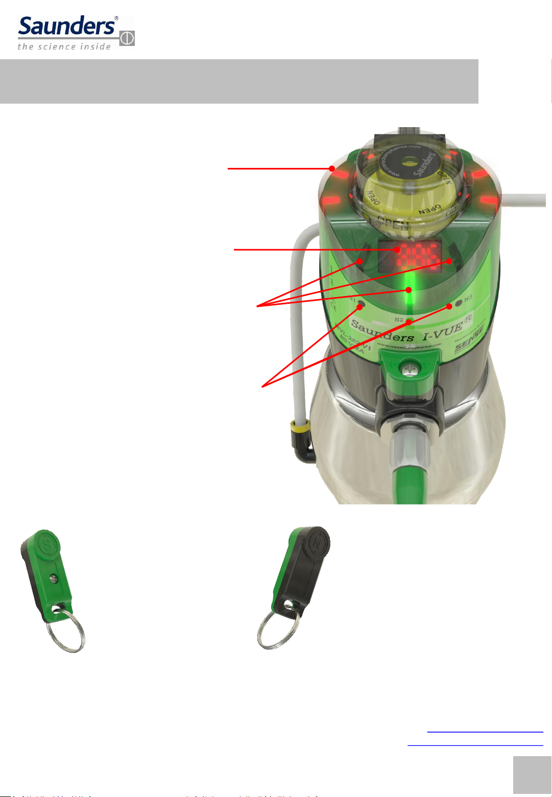
Overview 4
Basic Installation Guide & Hazardous Area Installation 5
(Automatic) Self-Calibration (Integral Solenoid) 9
Hand-Calibration (Remote Solenoid) 10
Switching Outputs Options 13
Forcing the Integral Solenoid 14
Troubleshooting 15
Rev 1.00
Quick Start Guide Basic Safety Instructions
These instructions do not make allowance for:
Contingencies and events which may arise during the installation, operation, and maintenance of the sensor.
Local safety regulations; the operator is responsible for observing these regulations, also with reference to the
installation personnel.
High Pressure
Before dismounting pneumatic lines and valves, turn off the pressure and vent the lines.
To prevent damage, make sure that all the pneumatics connections are made correctly.
Electrical Risks
Before working on the sensor, switch off the power supply and prevent reactivation.
Observe applicable accident prevention and safety regulations for electrical equipment.
Hazardous Situation
To avoid injury, ensure:
That the system cannot be activated unintentionally.
Installation and maintenance may be carried out by authorized technicians only.
After an interruption in the power or pneumatic supply, ensure that the process will be restarted in a defined
and controlled manner.
The sensor must be operated according to the operating instructions
Warning:
Do not connect or disconnect while circuit is live unless location is know to be non-hazardous.
The Safety Lock device must be used with M12 and 7/8" electrical connections for use in Hazardous Area Class
1, Division 2. Substitution of components may impair suitability for class I, division 2.
2