2easy 2-wire Series User manual

Door Station Model 603/Flush Mount
2-wire series
www.intelligenthomeonline.com
2-Button1-Button

-2-
Introduction
Door Station Model DT-603 is equipped with a high resolution colour CCD image sensor ARS 650TVL with
wide angle of view 105 degrees. White LEDs enable the door station to work efficiently at night. The door
station facia is made of medical stainless steel 2.5mm for better protection against cauterization. The call
button is made of durable zink alloy. The name label with back light is covered by fully secured and
flameproof 4mm plexiglass plate.
Door station intended for flush mount installtion and comes with wall box. Anti-tamper screws supplied for
better protection against vandalism.
IP54 protection rate
Parts and Functions
110 mm
188 mm
Camera Lens
Speaker
Nameplate
Call Button
Microphone
Night LEDs
Side View Mounting box
-1-

Introduction
TerminalsDescriptions
1 2 3
Lock Control Jumper
PL
S+ S-
Main Connection Port
BUS
Lock Control Jumper :To program electric lock type
Main Connect Port :To connect the bus line and electric lock
BUS :Connect to the bus line, no-polarity
PL :Additional power supply for the lock, connect to the power positive (power +)
S+ : Lock power (+) output
S - : Lock power (-) output
-2-

-3-
Mounting
Door Station Mounting
1 2
54
Cut out an appropriate size hole, and mount
the wall box
Place the front panel into the mounting
box. Screw in with security screws
3
Place name label if required. Connect the cable
Replacing Name Label
STEP 1
Unscrew the screws
STEP 2
Replace name label
Name label

-4-
1-Monitor Connection
System Wiring and Connections
BUS(IM) BUS(DS)
PC6
AC~
-
+
L1 L2 PL S+ S-
Doorbell Button
Switch
1 2 3
ON
DIPS
Multiple Door Stations Connection
100~240VAC
DBC4A
A B C D
OFF
ON
Impedance
switch
L1 L2 PL S+ S- L1 L2 PL S+ S- L1 L2 PL S+ S- L1 L2 PL S+ S-
1# Camera2# Camera3# Camera
4# Camera
Address:3 Address:2 Address:1 Address:0
BUS(IM) BUS(DS)
PC6
AC~
If system has more than one door station installed, program their ID address before mounting them
(see page 10 of manual)

-5-
Multiple Monitors Connection: Daisy Chain
Code=
14
Code=
15
Address:0
BUS(IM) BUS(DS)
PC6
AC~
100~240VAC
Code=0
Up to 15 x video monitors (Aura, Alecto, Leda, Iris) can be connected in one system

-6-
Multiple Monitors Connection: Star with DBC4 Distributor
Code=0
OFF ON
OFF ON
DBC4A
A B C D
DBC4A
A B C D
Impedance
switch
Impedance
switch
Address:0
100~240VAC
BUS(IM) BUS(DS)
PC6
AC~
Code=2
Code=1
Code=3
Code=12
Code=14
Code=13
Code=15
Up to 15 x video monitors (Aura, Alecto, Leda, Iris) can be connected in one system

-7-
Electric Lock Connection
Lock Controlled with Internal Power
Lock can be powered from Door Station if:
The lock is ‘Power-on-to-unlock’
The lock is 12V, and holding current is less
than 250mA
‘Unlocking Mode’ paramenter would be 0
(default, no need extra programming)
EB
*
LOCK
PL S+S-
Electric lock, the jumper position in 2-3
1 2 3
BUS
Magnetic lock, the jumper position in 1-2
1 2 3
Door Lock Controlled with Dry Contact
Note:
1. The external power supply must be
used according to the lock
2. The jumper must be taken off
before connecting
3. Setup the Unlock Mode of Monitor
for different lock types
•Power-on-to-unlock type:Unlock
Mode=0 (by default)
•Power-off-to-unlock type:Unlock
Mode=1
LOCK
Take off the Jumper
POWER
SUPPLY
BUS PL S+S-

Unlock parameter settings via monitor (Aura, Alecto)
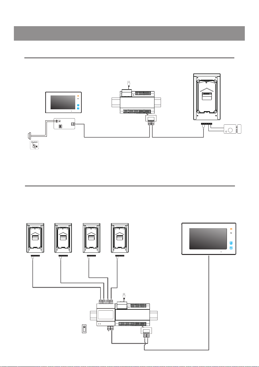
1. Door station must be connected and powered up
2. Electric or Magnetic lock must be connected before programming
3. Programming should be done on one monitor only. Settings will be synced with door station
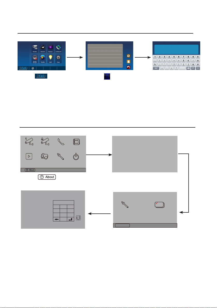
1.Touch icon 2.Touch UNLOCK
button and hold for 2s
3.A digital keypad will
opens
About
Local Address 00.00
Video Standard AUTO
System Verson 00.01.00
Display Driver 1.0
Front 1.0
UI 1.0
INSTALLER SETUP 123
_
Unlock parameter settings via monitor (Cronus)
1.Touch icon 2.Touch the screen and hold for 2s
3.Touch Installer setup icon
4. A digital keypad will opens
Manual
Monitor
Monitor
Memory
Playback
Album User Setup
09/30/2015Thu.16:41
Close
Intercom Multimedia
H/W : --- a1.3
S/W: V17.11.418.00
Local addr: ---
Unlock timing: ---
Video standard: -
UI-CODE: ---
MCM-VER.: ---
Updated: ---
Home
Installer
setup
Caliber
TouchScreen
Code Number:[----]
[0010]#:Remove all remote control
[0011]#:Add remote control
[8000]#:Set as master unit 0
[8001]#:Set as slaver unit 1
[8002]#:Set as slaver unit 2
[8003]#:Set as slaver unit 3
[8004]#:Set as guard unit
[8005]#:Set as not guard unit
[8006]#:Panel on as slaver unit called
[8007]#:Panel off as slaver unit called
[8008]#:Date format:MM/DD/YYYY
[8009]#:Date format:DD/MM/YYYY
[8010]#:Set lock mode to 0
[8011]#:Set lock mode to 1
[8021]~[8029]
#Set the lock time of 1~9s
Multi language settings:
---
1
4
78
0
9
6
5
23
Cancel
Installation settings:
Using the keypad, type in following codes:
8010 # for ‘Power-on-to-unlock’ mode
8011 # for ‘Power-off-to-unlock’ mode
Next step is to set unlocking time
8021# ~8029# unlocking time 1-9s
NOTE: Lock must be connected before programming. Programming should be done on one monitor only.
Settings will be synced with door station
-8-

DIP User code
code=0
code=1
code=2
code=3
code=4
code=6
code=7
code=8
code=9
code=10
code=11
code=12
code=13
code=14
code=15
code=5
DIP User code DIP User code
1 2 3 4 5 6
ON
1 2 3 4 5 6
ON
1 2 3 4 5 6
ON
1 2 3 4 5 6
ON
1 2 3 4 5 6
ON
1 2 3 4 5 6
ON
1 2 3 4 5 6
ON
1 2 3 4 5 6
ON
1 2 3 4 5 6
ON
1 2 3 4 5 6
ON
1 2 3 4 5 6
ON
1 2 3 4 5 6
ON
1 2 3 4 5 6
ON
1 2 3 4 5 6
ON
1 2 3 4 5 6
ON
1 2 3 4 5 6
ON
There are 6 x DIP switches on the rear of video monitor and they are used to configure the ‘User
Code’ for each monitor. Use Tables below for programming monitor ‘User Codes’
DIP switch 6 is ‘End of Line’ switch, which has to be set ‘On’ on all monitors connected via ‘Star’
with DBC-4 distributor
If monitors connected via ‘Daisy chain’, set DIP switch 6 ‘On’ on the last monitor in the chain only
DIP switches settings for Multiple Monitor system (Models Cronus, Leda, Iris)
DIP Setting DIP Setting
Monitor not at
the end of line
Monitor is at the end
of the line
1 2 3 4 5 6
ON
1 2 3 4 5 6
ON
-9-

-10-
Monitors with User Code 0~15 will response calls from Button A
Monitors with User Code 16~31 will response calls from Button B
Door Station ID Address
A
B
A
Up to 4 x Door Stations can be connected to one system. To find programming buttons A and B, remove steel
facia of door station
1)Power-on and within 5 sec
2)Press and hold button "B" for 3
seconds to enter programming
mode
background indicator Buzzer
beep+,beep
Press and hold both buttons "A"
and "B" for 3 seconds at the
same time
beep+,
(off)
Followed by pressing the "B"
button, each time you press "B"
button to replace the ID;
Note:The ID will cycle between
ID0
ID1
ID2
ID3.
beep one
(ash one)ID0:
beep twice
ID1:
beep 3 times
ID2:
beep 4 times
ID3:
(ash twice)
(ash 3 times)
(ash 4 times)
(ash)
background indicator Buzzer
6. Setup

-11-
Unlocking Time Setting via Door Station
Note: Unlocking time can be program via monitor as well
The unlocking time can be set to 1~30 seconds. The default is 1s
1)Power-on and within 5 sec
2)Press and hold "B" button for 3
seconds to enter programming
mode
background indicator Buzzer
beep+,beep
Press and hold "A" button for 3
seconds
beep+,
(off)
(ash)
background indicator Buzzer
At this time press and hold "B"
button,timing starts; release "B"
button to end the timing. The
time of press and hold "B" button
equal to unlock time.(Timing Unit:
1s)
beep once
per second
(ash once per second)
background indicator Buzzer

-12-
Ringtones Settings
Door Station has two reasurring ringtones: (A)-single ringtone, (B)-continuous ringtone
Can be switched off to silent (C) as well
Deafult - single ringtone (A)
Followed by pressing the "B"
button,each time you press "B" to
replace the ringtone mode;
Note:The ringtone mode will cycle
between [A]
[B]
[C].
beep ones
[A]:
beep twice
[B]:
beep 3 times
[C]:
(ash ones)
(ash twice)
(ash 3 times)
1)Power-on and within 5 sec
2)Press and hold "B" button for 3
sec to enter Programming mode
background indicator Buzzer
beep+,beep
Press and hold "B" button for 3
sec
beep+,
(off)
(ash)
background indicator Buzzer

-13-
•Power Supply : DC 24V
•Lock Power supply: 12Vdc, 300mA(Internal Power)
•Power Consumtion: Standby 33mA; Working status 110mA;
•Camera Image Sensor: Color ARS; 650 TV Lines
•Unlocking time: 1~30s
•Working temperature: -15ºC ~ 55ºC;
•Dimensions: H188 ×W110 ×D39mm
Precautions
• It is ok to clean stainless steel parts of Door Station with ‘Brasso’ for example.
Be careful with glass and plastic parts
• The unit is weatherproof. However do not spray high pressure water on it directly.
Excessive moisture may cause problems
• You must only use the power supply which is supplied or approved by the manufacturer
Specifications

-14-
7.Cables Requirements
This system transmits video and audio through the power cable. No Polarity connection
Recommended cables Uncreened: twisted pair, flex multi-cores, speaker cable, CAT5/CAT6
Minimum requirements 0.5mm cable up to 2mm (depends on distance)
Monitor quantity < 20
Cable Usage A B C
Twisted cable 2x0.75 mm260 60 60
Twisted cable 2x1 mm2150 150 100
Monitor quantity > 20
Cable Usage A B C
Twisted cable 2x1 mm270 70 70
Twisted cable 2x1.5 mm2100 100 100
B
A
C
DBC4
monitor
monitor
monitor
two or four monitors
100~240VAC
BUS(IM) BUS(DS)
PC6
AC~

-15-

The design and specications can be changed without notice to the user
Right to interpret and copyright of this manual are preserved
www.intelligenthomeonline.com
Other manuals for 2-wire Series
3
This manual suits for next models
1
Table of contents
Popular Accessories manuals by other brands

Keysight Technologies
Keysight Technologies E9320 Series Operating and service guide

Campbell
Campbell HFT3 instruction manual

Britax
Britax BOB Gear Duallie SNACK TRAY manual

iNels
iNels AirSOU-100L manual

Rivacold
Rivacold RCMR 350 Assembly instructions

PCB Piezotronics
PCB Piezotronics 353B12 Installation and operating manual