manuals.online logo
Brands
  1. Home
  2. •
  3. Brands
  4. •
  5. Savant
  6. •
  7. Recording Equipment
  8. •
  9. Savant SmartAudio SSA-4000 User manual

Savant SmartAudio SSA-4000 User manual

The Savant SmartAudio (SSA-4000-00) Quick Reference Guide provides all the steps necessary
to install the SSA-4000 controller.
Box Contents
(1) SmartAudio (SSA-4000)
(1) Installation Kit (075-0144-xx)
•(2) 1U Rack Mounting Brackets (071-0603-xx)
•(4) Phillips Screws for Brackets (M3 x 8MM Flat) (039-0017-xx)
•(2) 6-Pin Screw Down Plug in Connector (028-9352-xx)
•(1) HDMI Locking Cable (3 feet) (CBL-3LHDMI-xx)
•(1) Power cord C13, (6 feet) (N. America) (064-0079-xx) or appropriate international power
cord
(1) Quick Reference Guide (this document)
Required System Component
(1) Savant Host (HST-XXXX or SVR-XXXX)
Specifications
Environmental
Environmental
Temperature
32° to 104° F (0° to 40° C)
Humidity
10% to 90% Relative Humidity (non-condensing)
Cooling
3 cubic feet per minute (CFM) recommended.
Maximum BTUs
61 BTUs per hour
Dimensions and Weight
Height
1.71 in/4.34 cm
Width
17.30 in/43.94 cm
Depth
8.69 in/22.08 cm
Weight
5.25 lb/2.38 kg (net weight) 7.8 lb/3.54 (shipping weight)
Rack Space
1U
Power
Power
Input Power
100-240V AC, 50/60 Hz, (1.8 Amp maximum)
Nominal Power
12 watt
Maximum Power
18 watt
Compliance
Compliance
Safety and Emissions
FCC Part 15 | S Mark | CE Mark | C-Tick
RoHS
Compliant
5
135
42
6 7 8
Front View of SSA-4000
1
Reset button (hole)
Resets Static IP address. Press and hold.
2
Power Bi-color LED
Green indicates the system has adequate power and is
operating normally.
Red indicates the system is in stand-by mode. In standby
most of the Controller circuitry is powered down.
Off indicates that the system is getting no power.
3
Status Bi-color LED
Green indicates the Host has established communications
with the embedded system.
Green flashing indicates the embedded system is ready
(running with DHCP IP address), but the Host has not
established communications with the embedded system.
Off indicates the embedded processor is resetting or is
powered up; and is booting the embedded firmware.
Red indicates the Host has determined the firmware needs to
be updated, but a problem occurred during the process that
will initiate a reset.
Red flashing indicates the embedded firmware is running, but
has not received a DHCP IP Address.
Amber indicates the Host is currently updating the embedded
firmware.
Amber flashing indicates the embedded system has a valid
link-local IP Address and is waiting to connect to the Host.
Hardware Failure
If the Controller has a hardware failure, the Status LED
indication will be interrupted every 3-seconds with a solid red
indication. For example, if the LED is flashing green when a
hardware failure occurs, the LED, in 3-second intervals, will
flash green, solid red, etc.
4
RS-232 LED
Green indicates RS-232 serial port data activity.
Off indicates no RS-232 serial port activity.
5
GPIO LED
Green indicates GPIO port signal activity.
Off indicates no GPIO port activity.
6
On/Off button (hole)
Insert pin into hole for about 5 seconds to place in standby
mode. The Power LED turns red. Insert the pin again for about
1 second to take system out of standby mode. The I/O power
switch on the back of Controller must be On (I) to enable this
function. To turn the power off for the entire system, use the
switch on the rear panel.
7
HDMI LED
HDMI Link between the Host and the SSA-4000.
Green indicates the external host is connected to the Host
HDMI port.
Off indicates the external host is not connected to the Host
HDMI port.
8
IR LED
Green indicates IR port signal activity.
Off indicates no IR port activity.
1 2 3 54 6 7
10 12
11 1389
Rear View of SSA-4000
1
Ethernet
RJ-45 10/100 Base-T, auto-negotiating port with Link/Activity
and Speed LEDs.
2
RS232/422/485 (1-4)
RJ-45 ports used to transmit and receive serial binary data
transmission. input
3
GPIO (1-4)
General Purpose Input and Output ports. Uses 6-pin screw-
down connector.
The digital GPIO ports are binary I/O ports used for contact
closure, trigger (output), or detect (input). The COM pin is
used for common ground. Pin 1 - 4 is used for input or output.
3
GPIO Input
When configured as an input, the port detects a voltage
present (GPIO input). GPIO inputs can safely detect the
presence of a voltage 0-30V DC with a threshold of
approximately 2.4V DC.
3
GPIO Output
When configured as an output, a GPIO port outputs a voltage
below 12V DC. The maximum current per port is 150
milliamps. The combined maximum current for all GPIO
outputs is 550 milliamps. An overcurrent condition shuts down
the output if that number is exceeded.
4
Host HDMI (1)
HDMI Host Audio Input port with locking HDMI connector.Used
for receiving up to 4 PCM streams (iTunes®) from the Host
(such as HST-4501).
5
Stereo In
4 Analog Audio Inputs (4 Right and Four Left)
6
Stereo Out
12 Stereo line-level audio outputs (12 Right and 12 Left RCA
jacks)
7
Fuse
100-240V, 2.5A—Fast acting fuse. This is field-replaceable.
8
Link/Activity LED
Green indicates an Ethernet link has been established.
Green flashing indicates Ethernet activity.
Off indicates an Ethernet link has not been established.
9
Ethernet Speed LED
Green indicates an Ethernet speed of 100 Mb.
10
IR (1-3)
Infrared transmitter ports. Uses 6-pin screw down connector.
(3.81mm each).
11
Digital Audio In
Receives stereo PCM signal from TosLink digital audio
connection.
12
I/O
On/Off switch -
I is used to power the controller to the On state.
O is used to power the controller to the Off state.
13
Input Power
100-240V AC, 50/60 Hz, 1.8 Amp
Savant SmartAudio
(SSA-4000)
Quick Reference Guide
009-0870-00
SSA-4000-00
040813
Document based upon target specifications. Specifications subject to change prior to final product release.
Wiring and Connectors
RS-232 Wiring
Controller RJ-45 (RS-232) Plug Pinouts
1 (Not Used for RS-232)
5 RXD (RS-232)
2 (Not Used for RS-232)
6 TX - (RS-232) (jumper)-Select
TDX for RS-232
3 TX+ (RS-232)
7 CTS (RS-232)
4 GND (RS-232)
8 RTS (RS-232)
RS-422/RS-485 Pinouts
Controller RJ-45 (RS-422/RS-485) Plug Pinouts
1 (RS+ (RS-422/485)
5 (Not used for RS-422/485)
2 RS- (RS-422/485)
6 TX- (RS-422/485)
3 TX+ (RS-422/485)
7 (Not used for RS-422/485)
4 GND (RS-422/485)
8 (Not used for RS-422/485)
Important
If you are using RJ-45 to DB-9 adapters not supplied by Savant, be sure to terminate any wires
required for communication/control within the adapter. Ensure that all wires required for
communication/control are not terminated in the connecter. Also, ensure that the unused wires in
the connector are cut to prevent them shorting out, as they are still terminated in the RJ-45
connector on the controller side
For more details on RS-232, RS-422 and RS-485 connectors, additional documentation is
available at: dealers.SavantSystems.com
Knowledge Base > Savant Hardware > SmartSystem Controllers > App Note RS-232
Conversion to DB-9 and RS-422/485 Pinout Application Note
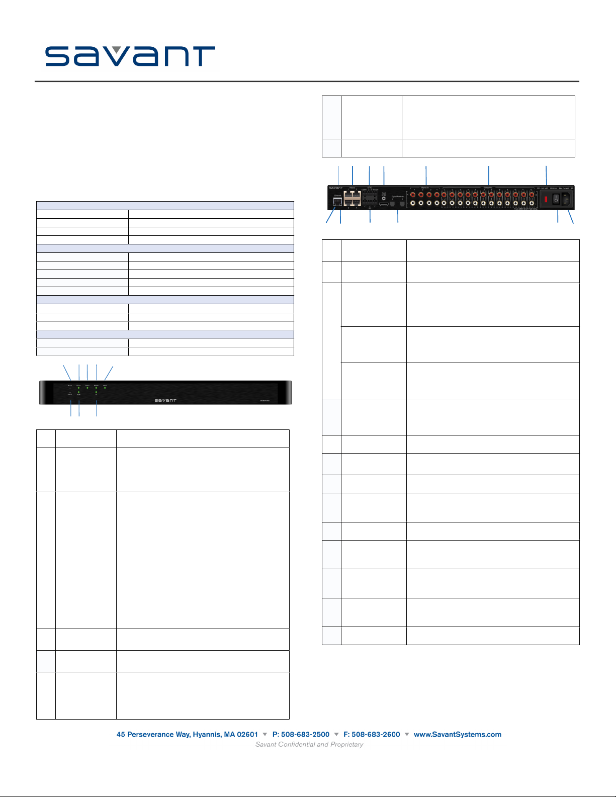
GPIO Pinouts
GPIO Port Layout and Pinouts
COM
1
2
3
4
COM
IR Port Layout and Pinouts
- 1 +
- 2 +
- 3 +
Interconnect the Network
The SSA-4000 requires business class/commercial grade network equipment in order to handle
the IP traffic between Savant SmartSystems™ network equipment. When configuring the
network ensure that all of the connected Savant units (including SSA-4000, HST-series and
SVR-series) are on the same local area network (subnet or LAN). When on the same network,
Savant units locate each other using the Bonjour®network protocol.
Network Changes Require Rebooting the SSA-4000
The embedded processor used in the Smart Controller needs to be rebooted after switching to a
new network with a new IP address range. If you do not reboot, the Controller will not sense the
network and IP address changes. The Status LED on the front panel of the Controller will start
to flash and log reports in System Monitor.
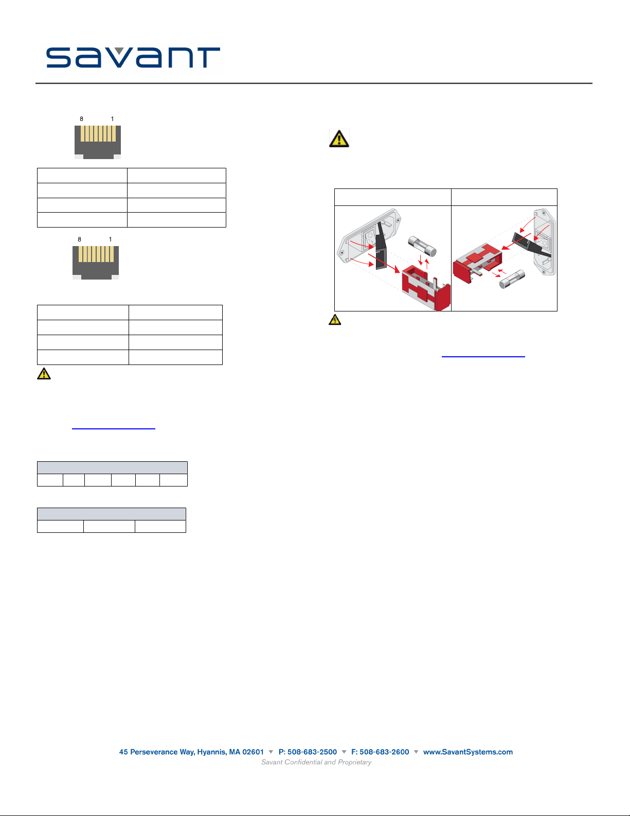
Replacing or Checking Fuse
To replace or check the fuse on the SSA-4000, do the following:
1. On the input power block, open the cover (hinged) to access the fuse cartridge. Refer to the
illustrations below.
2. Using a thin, flat tool remove the red cartridge.
Important: Before removing the fuse, note how and where the fuse is mounted in the
cartridge. The fuse must be replaced at the same location. Refer to the
illustration below.
3. Remove the existing fuse and replace with a new one.
4. Re-install the cartridge. Note that the cartridge fits in only one direction.
Horizontal Mounting
Vertical Mounting
ELECTRIC SHOCK: The 100-240V AC, 50-60 Hz source power poses an electric shock
hazard that has the potential to cause serious injury to installers and end-users.
Additional Documentation
Additional Documentation is available at: dealers.SavantSystems.com
Knowledge Base > Savant Hardware > SSA-4000
Savant SmartAudio
(SSA-4000)
Quick Reference Guide
009-0870-00
SSA-4000-00
040813
Document based upon target specifications. Specifications subject to change prior to final product release.
Copyright © 2013 Savant Systems LLC, SAVANT and RacePoint Blueprint are trademarks of Savant Systems, LLC.
Apple®, iPad®, iTunes®, iPod touch®, iPod® Classic and iPod nano® are registered trademarks or trade names of Apple Inc.
Savant Systems, LLC reserves the right to change product specifications without notice.

Other Savant Recording Equipment manuals

Savant SmartAudio SSA-3000 User manual

Savant

Savant SmartAudio SSA-3000 User manual

Savant SmartMedia SSM-3000 User manual

Savant

Savant SmartMedia SSM-3000 User manual

Popular Recording Equipment manuals by other brands

Audioplex PPS-4 installation manual

Audioplex

Audioplex PPS-4 installation manual

Korg D888 owner's manual

Korg

Korg D888 owner's manual

Korg D3200 owner's manual

Korg

Korg D3200 owner's manual

CircuitWerkes DR-10 Technical manual

CircuitWerkes

CircuitWerkes DR-10 Technical manual

Lutron Electronics PAV6M-120 installation guide

Lutron Electronics

Lutron Electronics PAV6M-120 installation guide

Mooer GE300 How to use

Mooer

Mooer GE300 How to use

Yamaha TX-7 Performance notes

Yamaha

Yamaha TX-7 Performance notes

Intellijel MIDI 1U manual

Intellijel

Intellijel MIDI 1U manual

Fostex D2424LV MKII Reference manual

Fostex

Fostex D2424LV MKII Reference manual

Renishaw HSI installation guide

Renishaw

Renishaw HSI installation guide

ARM IM-AD1 user guide

ARM

ARM IM-AD1 user guide

Broadcast 6000 user guide

Broadcast

Broadcast 6000 user guide

Russound CAA66 installation manual

Russound

Russound CAA66 installation manual

YOKOGAWA DXAdvancedR4 DX1000 user manual

YOKOGAWA

YOKOGAWA DXAdvancedR4 DX1000 user manual

BVR Instruments TS1 reference guide

BVR Instruments

BVR Instruments TS1 reference guide

Emerson SPS 4001B instruction manual

Emerson

Emerson SPS 4001B instruction manual

Clarion CI-5210 manual

Clarion

Clarion CI-5210 manual

Pyle Pro PPEQ-215 owner's manual

Pyle Pro

Pyle Pro PPEQ-215 owner's manual

manuals.online logo
manuals.online logoBrands
  • About & Mission
  • Contact us
  • Privacy Policy
  • Terms and Conditions

Copyright 2025 Manuals.Online. All Rights Reserved.