Table of Contents
Table of Contents......................................................................................................................................... 1
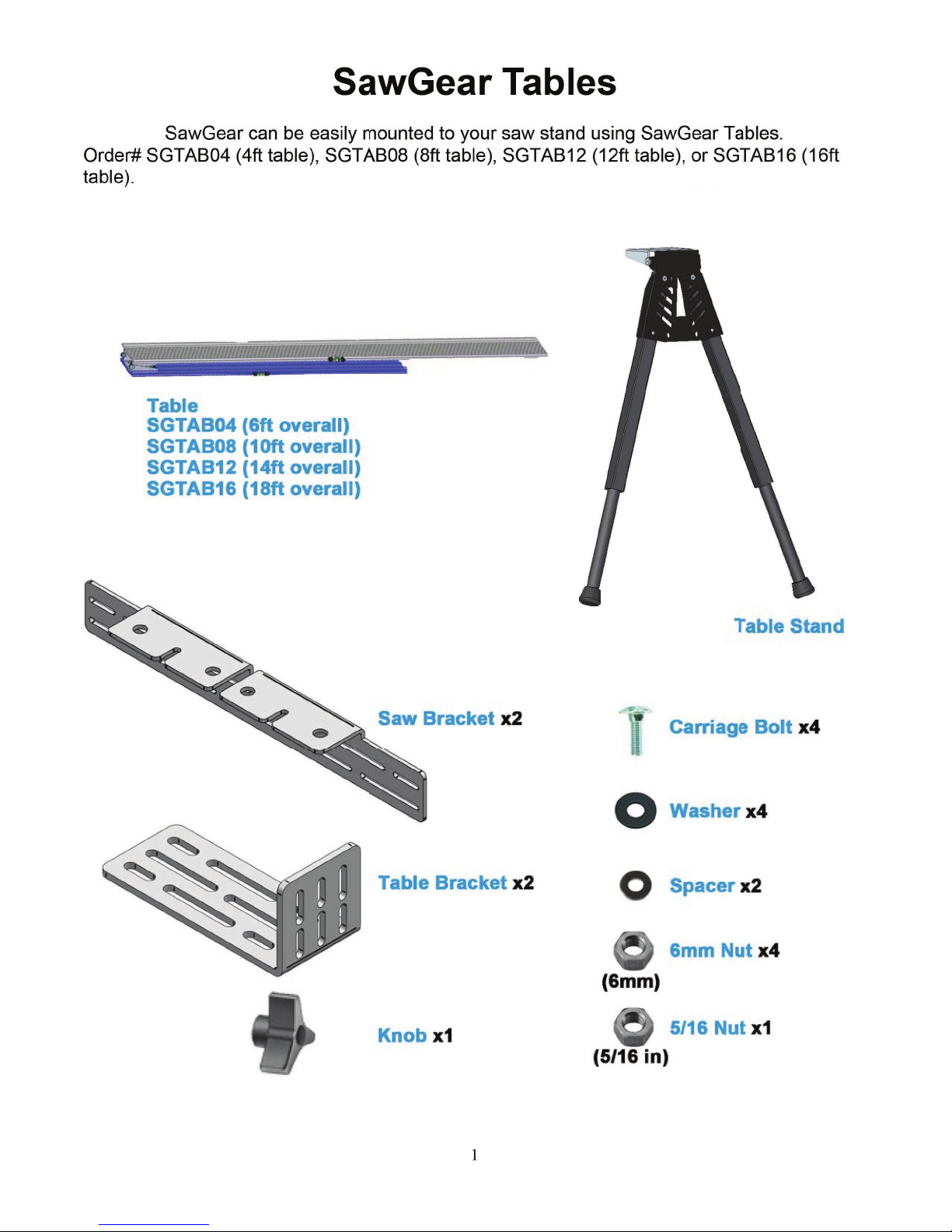
SawGear Tables............................................................................................................................................1
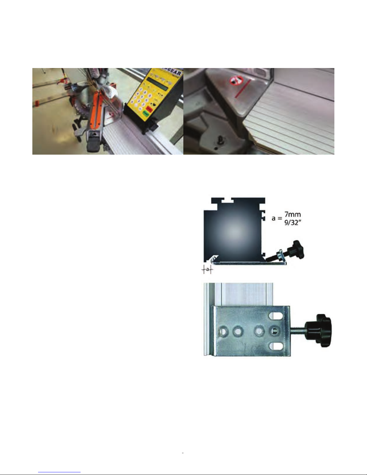
Trimming SawGear Tables.....................................................................................................................3
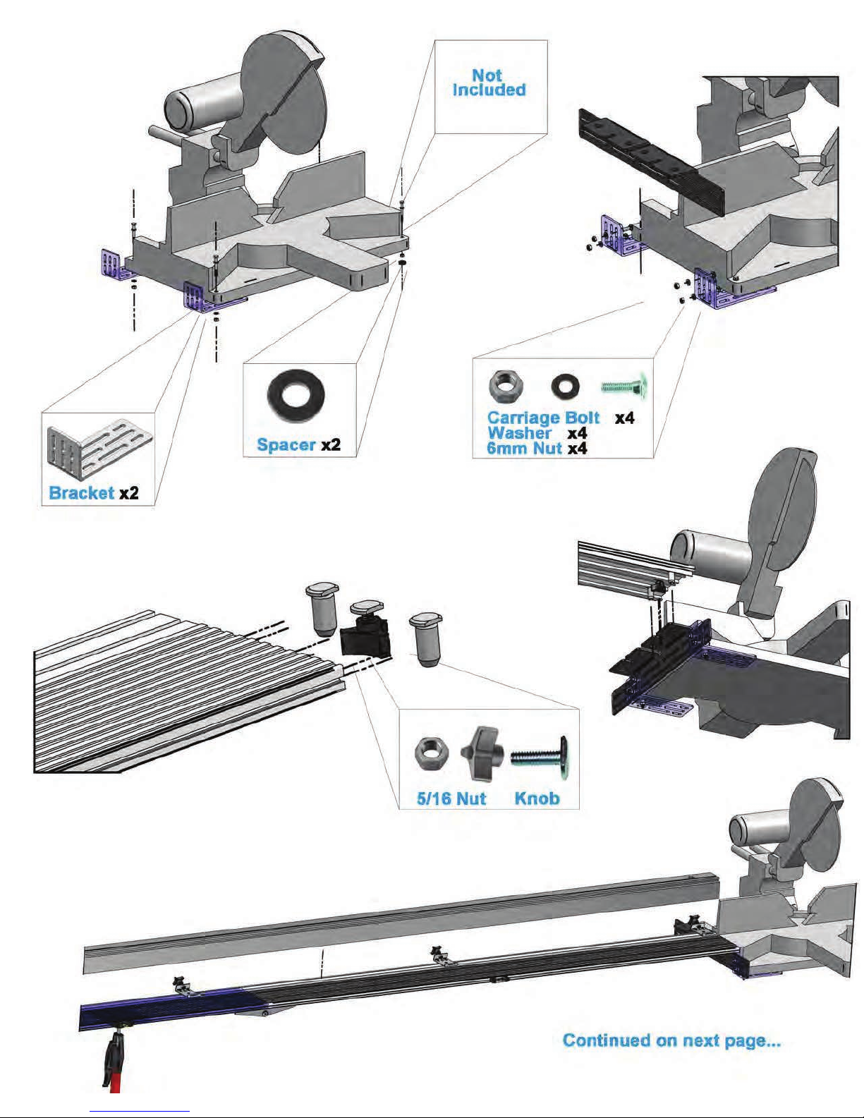
SawGear Bench Mount Brackets..................................................................................................................3
Secure SawGear in the brackets..............................................................................................................3
Dismounting SawGear from the saw stand............................................................................................ 3
Register Your Warranty............................................................................................................................... 4
Enable Your SawGear............................................................................................................................4
Miter Saw Accuracy.....................................................................................................................................5
Check Your Pivot Point..........................................................................................................................5
Adjusting the Miter Saw Pivot Point......................................................................................................6
Using SawGear to Adjust Pivot Point....................................................................................................6
SawGear Control......................................................................................................................................... 8
SawGear LCD Display.................................................................................................................................9
1st Power Up................................................................................................................................................ 9
Repeat a 1st Power Up................................................................................................................................10
Normal Power Up.......................................................................................................................................10
Start SawGear.............................................................................................................................................11
Set Sleep Mode...........................................................................................................................................11
Set Contrast............................................................................................................................................... 11
Password Protection.................................................................................................................................. 12
Change the Password..................................................................................................................................12
Deactivate the Password.............................................................................................................................13
Setting the Distance Between the Stop and the Blade................................................................................14
Calibrate Straight Cut Distance............................................................................................................14
Calibrate Miter Cut X Distance ...........................................................................................................14
Calibrate Miter Cut Y Distance ...........................................................................................................15
Calibrate Miter Cut Z Distance ............................................................................................................15
Calibrate Increment Distance.............................................................................................................. 15
Straight Cutting......................................................................................................................................... 15
Basic Operation................................................................................................................................... 15
45° Miter Cutting........................................................................................................................................15
Custom Miter Cutting.................................................................................................................................16
Using Crown & Miter Pro..........................................................................................................................17
Increment................................................................................................................................................... 20
Saving Dimensions with List......................................................................................................................20
Entering Feet, Inches and Fractions............................................................................................................21
Largest Number Display.............................................................................................................................22
Entering Feet and Decimal Inches..............................................................................................................22
Largest Number Display.............................................................................................................................23
Entering Non-Standard Fractions...............................................................................................................23
Entering Millimeters.................................................................................................................................. 24
Largest Number Display.............................................................................................................................24
Entering Negative Numbers.......................................................................................................................24
Correcting Entry Errors..............................................................................................................................25
Home Routine after Impact........................................................................................................................26
4