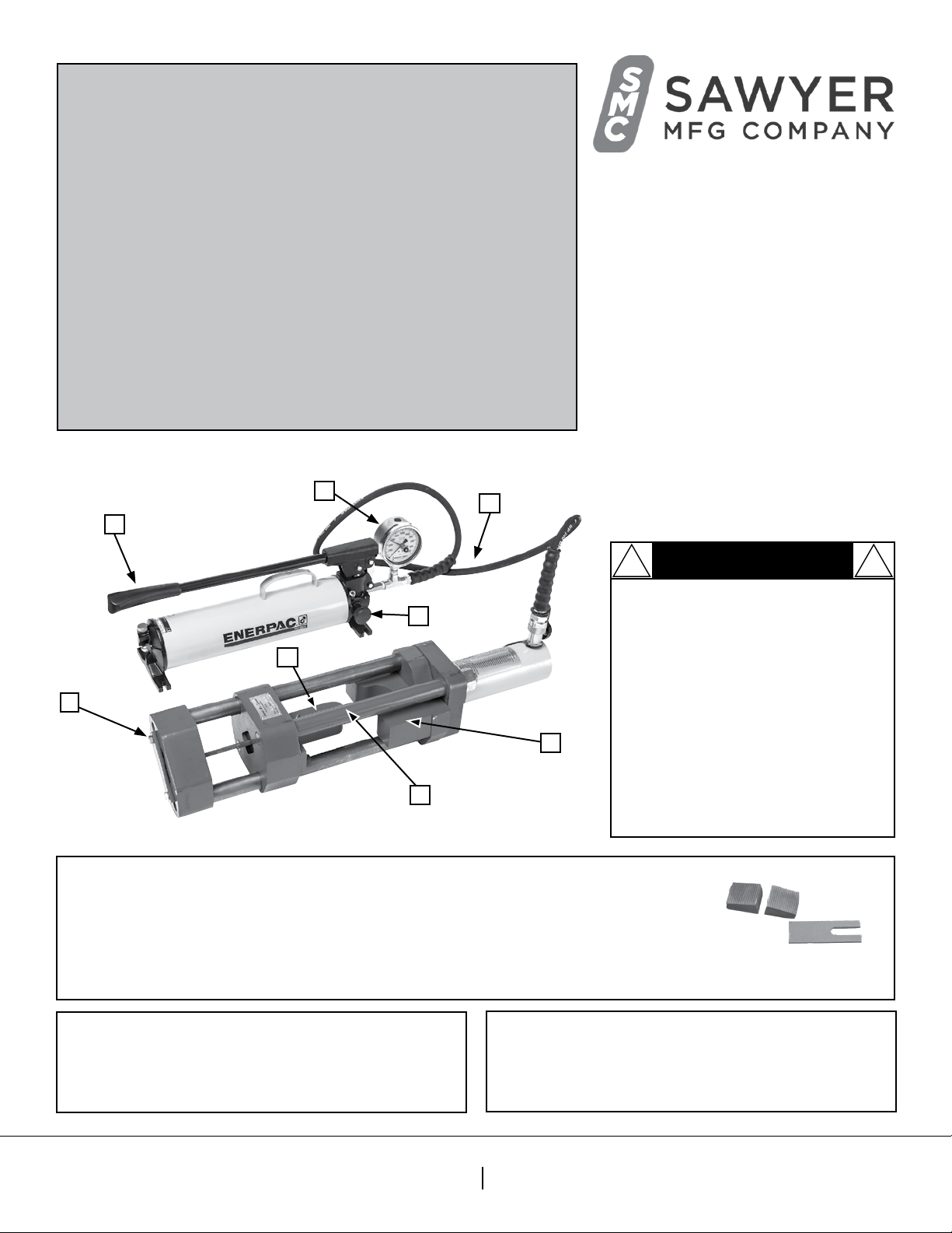
Sawyer 273-25 User manual

G
B
E
D
F
Sawyer Manufacturing Company
7799 S. Regency Dr., Tulsa, OK 74131 USA
F918.834.0318
info@sawyermfg.com
We appreciate your business!
Congratulaons on your new SAWYER product. We are proud to
have you as our customer and will strive to provide you with the best
service and reliability in the industry. This product is backed by our
extensive warranty and world-wide service network. To locate your
nearest distributor or service agency, please contact us at the phone
number and address listed on the boom of each page.
You are in good company!
Sawyer Manufacturing Company is the world leader in the design
and manufacture of pipeline and welding equipment and has been
since 1948. Sawyer equipment has become a standard in the industry
and connues to set the benchmark for quality and durability.
This user operaon manual has been made to instruct you for the best
use and operaon of your Sawyer product. Your sasfacon with our
products is our main goal. Please read this enre manual carefully,
nong all ps, notes and warnings. Safety always comes rst.
About Us
Warranty
All products manufactured by or for Sawyer Manufacturing Company are
guaranteed against defects due to faulty workmanship or materials for twelve
months from the date of purchase.
This guarantee is limited to the repair or replacement of any parts found to be
defecve, and no other liability–expressed, implied, or conngent–is assumed.
Record the following informaon for warranty purposes:
Where purchased:________________________________________________
Purchase date:___________________________________________________
Equipment Serial #:_______________________________________________
A. Hydraulic Relief Valve
B. ENERPAC Hydraulic Pump (526-5)
C. Hydraulic Hose Fing
D. Plunger
E. Die
F. Pressure Gauge (526-27)
G. Jaw Retainer (525AO-B)
H. Plunger “L” Bolt (A110B-C)
I. (4x) Jaws *not included*
J. (1) Jaws Tensioner *not included*
P 918.834.2550
sawyermfg.com
V1.2
CAUTION: Sawyer Manufacturing
Company oers a precise weld qualicaon
test for tensile strength and guided bend
operaons. The buildup of high pressure
inside the hydraulic guided bend and tensile
tesng machine can cause injury to personnel
and damage to equipment. To avoid a rapid
discharge, ensure that all pressure hoses are
connected and secure. When the hydraulic
pressure does not increase enough to bend
or break the sample, check the hydraulic uid
levels and add hydraulic uid as necessary.
Please refer to ENERPAC manual for
maintenance of ENERPAC pump.
! !
CAUTION
A
Guided Bend and
Tensile Tester
Manual
Models 273-25 & 273-55
For 25/55-Ton Applicaons
Parts Diagram
C
H

Sawyer Manufacturing Company
7799 S. Regency Dr., Tulsa, OK 74131 USA
F918.834.0318
info@sawyermfg.com
P 918.834.2550
sawyermfg.com
V1.2
Installation
1. Install die (E, Fig.1) and plunger (D, Fig.1) set for appropriate
coupon size thickness and specicaon. (ASME, API, AWS)
Note: Use 5/16” Allen head wrench.
2. Install jaws (I, Fig. 2) to tensile tester according to coupon
thickness and specicaon. (ASME, API, AWS)
3. Install hydraulic hose ng (C, Fig. 3) to tensile
tesng machine.
Tip: Unit can be mounted vercally or horizontally.
Tip: Unscrew plasc caps before installing hoses.
Note: Loosen oil ng for proper pump venlaon.
Tip: Thread hose ends with Teon tape to avoid leaks.
Installaon
Tools Needed For Assembly*
9/16” Nut Drive 5/16” Allen Wrench Pliers Large Crescent WrenchSledge Hammer
E
D
C
Fig. 1
Fig. 2
Fig. 3
*Not Included
I

Sawyer Manufacturing Company
7799 S. Regency Dr., Tulsa, OK 74131 USA
F918.834.0318
info@sawyermfg.com
P 918.834.2550
sawyermfg.com
V1.2
Operation
Operation
1. Place coupon across supports of die. (E, Fig. 5)
2. Depress the ENERPAC pump. (B, Fig. 6)
3. Plunge (D, Fig. 7) the sample into the die. (E, Fig. 7)
Note: A complete 180 degrees is recommended to complete the test.
4. Release pressure via Hydraulic Relief Valve (A, Fig. 8) and
remove sample from die. (E, Fig. 9)
Fig. 5
Fig. 6
Fig. 7
Fig. 8
E
B
D
Note: Refer to AWS, ASME and API specicaons for bended coupon samples.
Tip: Mount hydraulic hand pump down to stable environment.
Tip: Hydraulic hand pump can be mounted vercally or horizontally.
Guided Bend Operaon
Bend
This Bend test is designed to evaluate the quality of welds as a funcon of duclity in ferrous and nonferrous
products as evidenced by their ability to resist cracking during bending.
Reference:
3 Types of Bends:
A. Transverse side bend. The weld is transverse to the longitudinal axis of the specimen
which is bent so that either one of the side surface becomes the convex surface of the bent specimen.
B. Transverse face bend. The weld is transverse to the longitudinal axis of the specimen which is
bent so that the weld face becomes the convex surface of the bent specimen.
C. Transverse root bend. The weld is transverse to the longitudinal axis of the specimen
which is bent so that the weld root becomes the convex surface of the bent specimen.
Note: For more informaon please refer to the following publicaons:
AWS D1.2–D1.2M: 2003; API 5LC (R2006); API 1104 (R2010).
A
Fig. 9

Sawyer Manufacturing Company
7799 S. Regency Dr., Tulsa, OK 74131 USA
F918.834.0318
info@sawyermfg.com
P 918.834.2550
sawyermfg.com
V1.2
1. Install coupon into jaws. (I, Fig. 10)
A. Loosen plunger “L” bolt. (H, Fig. 11)
B. Push spring loaded jaws (I) on back of plunger (D) to
insert coupon. (Fig. 12)
Note: Use jaw tensioner to ghten jaws against coupon. (Fig. 13)
C. Place remaining jaws (I) around coupon unl it ts snug
and the coupon is clear of the jaw retainer. (G, Fig. 13)
2. Place jaw retainer (G, Fig. 14) in the down posion.
Note: Tighten retainer bolts using a 9/16” nut drive.
3. Move travel head away from machine by depressing
ENERPAC pump. (B, Fig. 15)
Tip: Use short pumps to speed the process.
4. Keep depressing ENERPAC pump (B, Fig. 16) unl coupon
sample breaks.
Note: Refer to pump pressure chart.
5. Release pressure from pump/crank by turning
relief valve. (A, Fig. 17)
6.Remove sample from jaws. (I, Fig. 18)
Tip: Use a hammer to loosen sample.
A. Loosen 9/16” retainer bolts (Fig. 19).
B. Pull jaw retainer up. (Fig. 20)
C. Remove sample from jaws.
Note: Refer to AWS, ASME and API specicaons for tensile test coupon samples.
Tip: Mount hydraulic hand pump down to stable environment.
Note: Hydraulic hand pump can be mounted vercally or horizontally.
Tip: When loading sample pull to highest point in jaws for easier removal.
Note: Make sure relief valve is ght before operaon.
I
Operation
Fig. 15
Fig. 14
Fig. 10
Fig. 16
Fig. 17
Fig. 18
Fig. Fig. 2020
Fig. Fig. 1919
G
Fig. 11
Fig. 13
Fig. 12
H
B
This manual suits for next models
1
Table of contents
Other Sawyer Test Equipment manuals
Popular Test Equipment manuals by other brands

Digital Watchdog
Digital Watchdog SiteWatch DW-DTWT quick start guide

AEMC instruments
AEMC instruments 6416 user manual

BI COMMUNICATIONS
BI COMMUNICATIONS Lan Caster ProST user manual

Amphenol
Amphenol Temposonics M Series user manual

Greenlee
Greenlee 45058 instruction manual

Benning
Benning IT 115 operating manual

FLO-DYNAMICS
FLO-DYNAMICS Test-Quick LPVLT-100 Operation manual

Gossen MetraWatt
Gossen MetraWatt SECULIFE ST PRO operating instructions

Instron
Instron MicroTorsion MT1 operating instructions

SENTRONIC
SENTRONIC M-SYSTEM M2MNV manual

Vernier
Vernier Go Direct GDX-VSMT quick start guide

Tektronix
Tektronix 71310 instruction manual