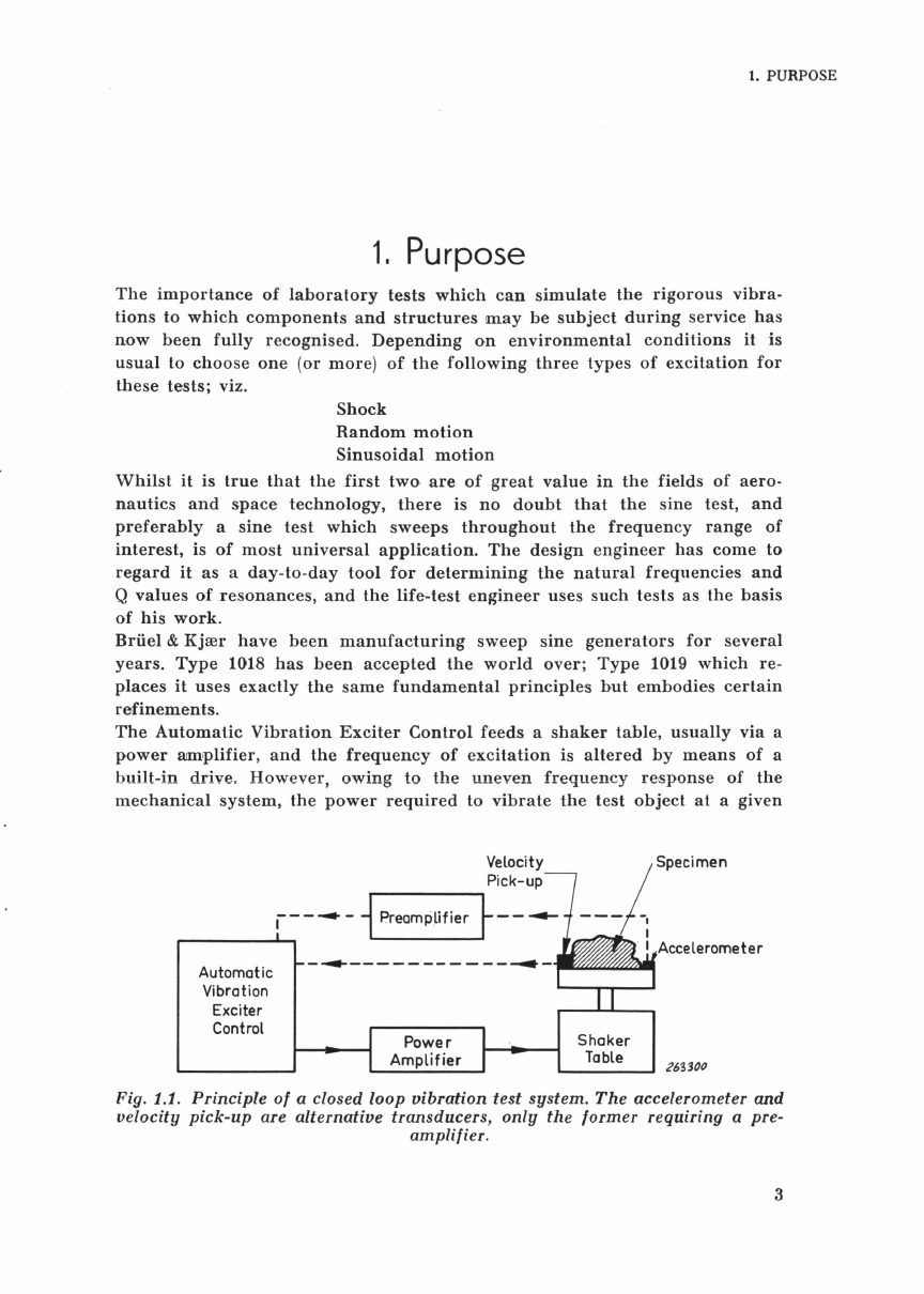
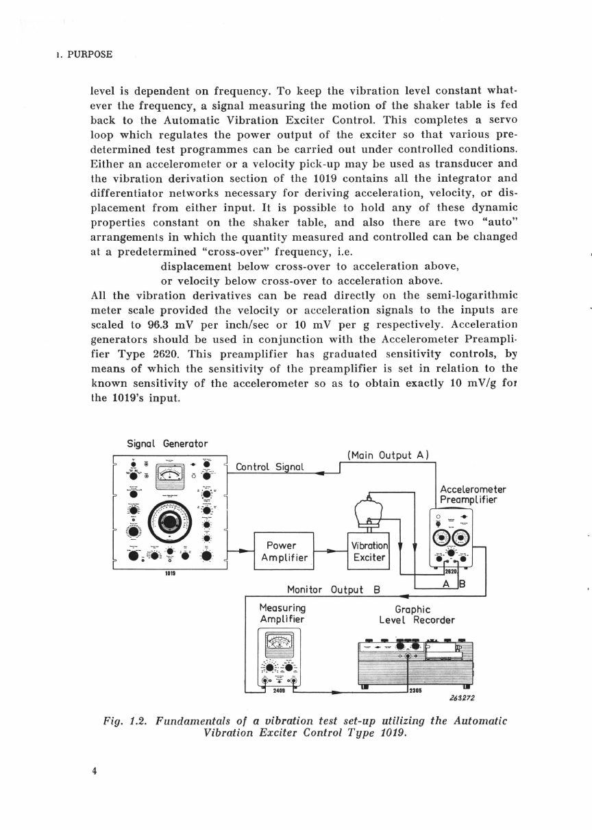
Brüel & Kjær 1019 User guide

Automatic
Vibration
Exciter
Control
Type 1019/39
• i
·"=
i
..:~
® ·•.
J
~
-
::"
~
:
-
·
·il
:·
·.
!.,
The
Autom
a
tic
Vibr
a
tion
Exci
ter
Control
is a
spe-
cially
designed
signal
source
for
the
vibration
te
sting
of
mechanical
and
electro-m
e
chanical
components
in
the
frequency
range
5 c js
to
10
kc
/s.
BHUEL&KJJEH
N~rum,
Denmark
eye
80
05 00
.
~
BRUKJA, Copenhagen . Telex: 5316
88
1019
1
10
39


Automatic Vibration Exciter Control
Type 1019/39
NOVEMBER
1965

Contents
1.
Purpose
. . . . . . . . . . . . . . . . . . . . . . . . . . . . . . . . . . . . . . . . . . . . . . . . . . . . . . . . . . 3
2.
Description
. . . . . . . . . . . . . . . . . . . . . . . . . . . . . . . . . . . . . . . . . . . . . . . . . . . . . . . 6
2.1.
Oscillator
. . . . . . . . . . . . . . . . . . . . . . . . . . . . . . . . . . . . . . . . . . . . . . . . . . . . 6
2.2.
Automatic
Frequency
Scan
. . . . . . . . . . . . . . . . . . . . . . . . . . . . . . . . . . . . 7
2.3.
Vibration
Derivation
. . . . . . . . . . . . . . . . . . . . . . . . . . . . . . . . . . . . . . . . . . 7
2.4.
Compressor
Arrangement
. . . . . . . . . . . . . . . . . . . . . . . . . . . . . . . . . . . . . . 8
2.5.
Meter
Section
. . . . . . . . . . . . . . . . . . . . . . . . . . . . . . . . . . . . . . . . . . . . . . . . 9
2.6.
Frequency
Calibration
. . . . . . . . . . . . . . . . . . . . . . . . . . . . . . . . . . . . . . . . 9
2.7.
Remote
Control
. . . . . . . . . . . . . . . . . . . . . . . . . . . . . . . . . . . . . . . . . . . . . . . 9
2.8.
Parallel
Operation
of
Generators
. . . . . . . . . . . . . . . . . . . . . . . . . . . . . . 10
3.
Control
l{nobs,
Terminals
etc.
. . . . . . . . . . . . . . . . . . . . . . . . . . . . . . . . . . . . . .
11
4.
Operation
as
Vibration
Meter
. . . . . . . . . . . . . . . . . . . . . . . . . . . . . . . . . . . . . .
21
4.1.
Setting
to
Mains
Voltage
......................................
21
4.2.
With
a
Velocity
Pick-up
......................................
21
4.3.
With
an
Accelerometer
. . . . . . . . . . . . . . . . . . . . . . . . . . . . . . . . . . . . . . . . 22
5.
Operation
as
Shaker
Control
. . . . . . . . . . . . . . . . . . . . . . . . . . . . . . . . . . . . . . 24
5.1.
Calibration
of
Frequency
Scale
................................
24
5.2.
Adjustment
of
Automatic
Frequency
Scanning
Range
............
24
5.3.
Uni-directional
Frequency
Scanning
............................
25
5.4.
Partial
Blocking
of
Frequency
Scale
Range
. . . . . . . . . . . . . . . . . . . . 26
5.5.
Setting
of
Scanning
Speed
. . . . . . . . . . . . . . . . . . . . . . . . . . . . . . . . . . . . 28
5.6.
Setting
Regulation
Speed
. . . . . . . . . . . . . . . . . . . . . . . . . . . . . . . . . . . . . . 28
5.
7.
Possibilities
. . . . . . . . . . . . . . . . . . . . . . . . . . . . . . . . . . . . . . . . . . . . . . . . . . 29
5.8.
Setting
Auto
Cross-Over
Frequency
............................
30
5.9
Summary
of
Preparatory
Operations
............................
30
5.10.
Operation
Schemes
..........................................
31
6.
Operation
with
Level
Recorder
. . . . . . . . . . . . . . . . . . . . . . . . . . . . . . . . . . . . 3b
6.1.
Possibilities
..................................................
35
6.2.
Synchronization
with
Level
Recorder
. . . . . . . . . . . . . . . . . . . . . . . . . . 35
6.3.
Monitoring
Shaker
Table
Motion
. . . . . . . . . . . . . . . . . . . . . . . . . . . . . . 38
6.4.
Plotting
System
Frequency
Response
. . . . . . . . . . . . . . . . . . . . . . . . . . 39
6.5.
Recording
Specimen
Vibration
................................
41
6.6.
Recording
Two
Quantities
Simultaneously
. . . . . . . . . . . . . . . . . . . . . . 42
7.
Remote
Control
Facilities
..........................................
44
7.1.
Start
and
Stop
of
Frequency
Scan
..............................
44
7.2.
Forward
and
Reverse
Frequency
Scan
..........................
44
7.3.
Stand
by
.....................................................
44
7.4.
Changing
Scanning
Speed
. . . . . . . . . . . . . . . . . . . . . . . . . . . . . . . . . . . . . . 44
8.
Master-Slave
System
. . . . . . . . . . . . . . . . . . . . . . . . . . . . . . . . . . . . . . . . . . . . . . 46
8.1.
Principle
.....................................................
46
8.2.
Interconnections
..............................................
47
8.3.
Setting
Up
....................................................
48
8.4.
Adjusting
Individual
Vibrations
(Level
and
Phase)
. . . . . . . . . . . . . . 49
8.5.
Command
of
the
System
. . . . . . . . . . . . . . . . . . . . . . . . . . . . . . . . . . . . . . 49
Specification
. . . . . . . . . . . . . . . . . . . . . . . . . . . . . . . . . . . . . . . . . . . . . . . . . . . . . . . . 50

1. PURPOSE
1.
Purpose
The
importance
of
laboratory
tests
which
can
simulate
the
rigorous
vibra-
tions
to
which
components
and
structures
may
be
subject
during
service
has
now
been
fully
recognised.
Depending
on
environmental
conditions
it
is
usual
to
choose
one
(or
more)
of
the
following
three
types
of
excitation
for
these
tests;
viz.
Shock
Random
motion
Sinusoidal
motion
Whilst
it
is
true
that
the
first
two
are
of
great
value
in
the
fields
of
aero-
nautics
and
space
·
technology,
there
is
no
doubt
that
the
sine
test,
and
preferably
a
sine
test
which
sweeps
throughout
the
frequency
range
of
interest,
is
of
most
universal
application.
The
design
engineer
has
come
to
regard
it
as
a
day-to-day
tool
for
determining
the
natural
frequencies
and
Q
values
of
resonances,
and
the
life-test
engineer
uses
such
tests
as
the
basis
of
his
work.
Briiel
& Kjrer
have
been
manufacturing
sweep
sine
generators
for
several
years.
Type
1018
has
been
accepted
the
world
over;
Type
1019
which
re-
places
it
uses
exactly
the
same
fundamental
principles
but
embodies
certain
refinements.
The
Automatic
Vibration
Exciter
Control
feeds
a
shaker
table,
usually
via
a
power
amplifier,
and
the
frequency
of
excitation
is
altered
by
means
of
a
built-in
drive
.
However,
owing
to
the
uneven
frequency
response
of
the
mechanical
system,
the
power
required
to
vibrate
the
test
object
at
a given
Automatic
Vibration
Exciter
Control
r-------.
Velocity
Pick-up
_
_.
___________
__
Shaker
Table 263300
Fig. 1.1. Principle
of
a closed loop vibration test system.
The
accelerometer and
velocity
pick-up
are alternative transducers,
only
the former requiring a pre-
amplifier.
3

1. PURPOSE
level is
dependent
on
frequency.
To
keep
the
vibration
level
constant
what-
ever
the
frequency,
a
signal
measuring
the
motion
of
the
shaker
table
is
fed
back
to
the
Automatic
Vibration
Exciter
Control.
This
completes
a
servo
loop
which
regulates
the
power
output
of
the
exciter
so
that
various
pre
-
determined
test
programmes
can
be
carried
out
under
controlled
conditions.
Either
an
accelerometer
or
a
velocity
pick-up
may
be
used
as
transducer
and
the
vibration
derivation
section
of
the
1019
contains
all
the
integrator
and
differentiator
networks
necessary
for
deriving
acceleration,
velocity,
or
dis-
placement
from
either
input.
It
is
possible
to
hold
any
of
these
dynamic
properties
constant
on
the
shaker
table,
and
also
there
are
two
"auto"
arrangements
in
which
the
quantity
measured
and
controlled
can
be
changed
at
a
predetermined
"cross-over"
frequency,
i.e.
displacement
below
cross-over
to
acceleration
above,
or
velocity
below
cross-over
to
acceleration
above.
All
the
vibration
derivatives
can
be
read
directly
on
the
semi
-
logarithmic
meter
scale
provided
the
velocity
or
acceleration
signals
to
the
inputs
are
scaled
to
96.3 mV
per
inch/sec
or
10
mV
per
g
respectively.
Acceleration
generators
should
be
used
in
conjunction
with
the
Accelerometer
Preampli·
fier
Type
2620.
This
preamplifier
has
graduated
sensitivity
controls,
by
means
of
which
the
sensitivity
of
the
preamplifier
is
set
in
relation
to
the
known
sensitivity
of
the
accelerometer
so
as
to
obtain
e·
xactly
10
mV/g
for
the 1019's
input
.
Signal Generator
••
0 .,. ,..,
·i r
':
i
:·
,.,
·•
··
·-;
::-
i ::
..
, .=• = ·:· ·
1119
Control S
Monitor
Ou
Measuring
Amplifier
t A)
e
Accelerometer
Preamplifier
Graphic
Level Recorder
Fig. 1.2.
Fundamentals
of
a vibration
test
set-up
utilizing
the
Automatic
Vibration
Exciter
Control
Type
1019.

1. PURPOSE
It
is
often
of
interest
to
obtain
a
graphical
plot
of
the
response
of
vibrated
specimens.
This
is
conveniently
achieved
by
synchronizing
the
frequency
scan
of
the
1019
with
the
frequency
graduations
on
chart
paper
running
through
a
Briiel
& Kjrer
Level
Recorder
Type
2305.
One
Automatic
Vibration
Exciter
Control
can
be
set
up
as
a
"master"
to
control
up
to
three
similar
"slave"
units.
In
such
an
arrangement
the
"master"
controls
its
own
shaker
table
as
well
as
the
frequency
of
the
output
signal
from
the
"slaves".
Each
"slave",
however,
can
control
the
vibration
level
of
its
associated
shaker.
It
is
thus
possible
to
synchronize
the
movement
of
up
to
4
vibration
exciters
for
the
testing
of
large
specimens.
Furthermore,
the
phase
relationship
between
the
"master"
and
"slave"
output
signal
can
be
adjusted
over
a
full
360°
angle.
The
Automatic
Vibration
Exciter
Control
Type
1019
(cabinet
version)
can
also
be
supplied
for
standard
19''
rack
mounting
as
Type
1039.

2.
DESCRIPTION
2.
Description
The
principle
of
operation
is
illustrated
in
the
block
diagram
Fig.
2.1
Fixed
Oscillator
Vari-fl
Amplifier
"Compressor"
Socket
Function
Selector
Vibration
Generator
Accel.
Range
Displ.-Vel.
Range
Derivation
A
v
D
Output
Amplifier
"O
scillator
"
Jack
"Vibration"
Jack
~:-.:::~:"
Gen.
Mains
263299
Fig. 2.1. Principle
of
the
Automatic
Vibration
Exciter
Control.
2.1. Oscillator.
6
The
oscillator
works
on
the
heterodyne
principle;
by
beating
together
two
comparatively
high
frequencies-one
from
a
variable
and
one
from
a
fixed
oscillator-an
output
frequency
of
between
5
and
10ooo
c/s
is
produced.
The
fixed
oscillator
oscillates
at
either
30
kc/s
or
35
kc/s,
depending
on
the
setting
of
FREQUENCY
RANGE.
The
variable
oscil-
lator
frequency
is
between
25
kc/s
and
30
kc/s,
as
determined
by
the
position
of
the
main
tuning
capacitor.
There
are
therefore
two
fre-
quency
ranges,
viz.
5-5ooo
c/s
or
5005-lOooo
c/s
The
first,
which
is
covered
in
a
true
logarithmic
sweep,
is
marked
directly
on
the
large
circular
scale.
The
second
range
is
not
logarithmic,
the
frequency
being
reckoned
by
adding
5ooo
c/s
to
the
scale
reading.

2. DE')CRIPTION
2.2. Automatic Frequency Sean.
The
frequency
range
can
be
continuously
scanned
with
various
speeds
by
a
built-in
synchronous
motor
which
can
be
reversed
electrically.
The
motor
speed
can
be
changed
in
six
coarse
steps,
covering
the
range
o.3
to 100
degrees/min.
Within
e·
ach
of
the
six
steps
the
speed
can
be
fine
adjusted
in
22
steps.
Using
bo.th
controls
provided,
there
are
132
possible
scanning
speeds
from
o.3
to
300
degreesfmin.
*)
The
frequency
range
for
to-and-fro
scanning
is
easily
adjusted.
Uni-
directional
scanning
throughout
360° is
also
possible,
the
output
being
cut
dead
while
the
pointer
is
on
the
blank
part
of
the
dial,
and,
if
the
scanning
range
is
to
be
reduced,
while
on
the
unwanted
sectors
of
the
scale.
2.3. Vibration Derivation.
The
input
signal,
which
can
be
from
'
either
an
accelerometer
or
a
velocity
pick-up,
is
processed
according
to
the
following
table,
depend-
ing
on
which
quantity
has
been
selected
by
FUNCTION
SELECTOR.
Table
I.
Frequency-weighting
in
the
vibration derivation section.
Input
\To
read
Acceleration
Velocity
Displacement
Acceleration
Direct
-6dB/Oct.
-12
dB/Oct.
Velocity
+6
dB/Oct.
Direct
-6
dB/Oct.
Note:
Differentiation;
Equivalent
to
slope
+6
dB/Oct.
Integration;
Equivalent
to
slop.:! - 6
dB/Oct.
Considerable
low-frequency
noise
is
inherent
in
any
measuring
system
involving
integration,
so
special
networks
(which
do
not
affect
the
measurements)
are
included
to
reduce
this
and
to
prevent
the
whole
system
from
"hunting".*
*)
In
the
two
"Auto"
positions
of
FUNCTION
SELECTOR
the
relays
governing
which
weighting
function
is
effective
at
a
given
instant
are
switched
at
a
predetermined
generator
frequency,
adjustable
between
8
and
1ooo
c/s.
The
acceptable
ranges
for
measurement
and
control
are
given
on
p.
8.
*
)Additionally
there
are
six
other
scanning
speeds
suit
a
ble for
achieving
synchronism
with
the
frequency-calibrated-paper
transport
on
the
Brfiel & Kjrer Level
Recorder
Type
2305.
**)
This
is a
low
frequency
system
oscillation
which
might
otherwise
occur
when
the
generator
frequency
is a few
thousand
cps.
7

2.
DESCRIPTION
Table II.
Frequency Ranges for Measurement
and
Control.
Displacement
10
20
50
100 200 500 1
000
2000
5000
10000
cfs
Velocity
10
20
50
100
.200
500
1000 2000 5000
10000
cfs
Acceleration
10
20
50
100
200
500
1000
2
00
0 5
000
10000
c/
s
IAuto
D-A
& Auto
V-A
Cross-over I f
:·:
·
!·:·:·
:·
:·:·:
·:
·:
l
:·:
·
:·:·:
-=·:·:
·
:·:·:·
!·:·
:·
:·:·
:·:·:·:
l
:·:·:·
:·:
·:·
:l
:-:-:-:
·:·
:·:·:·:·:
+
:·:·:·:·:·:-=·:·
l
10 20 50
100
200
500
1000
2000 5000
10000
cfs
26g278
Legend:
~
With Veloci
ty
Pic·
k-up
~
With
Accelerometer
C::::::::::j
Limits
for
Cross-over
lt
Exceeding . 5
kc/s
requires
the
H.
F.
range
2.4.
Compressor
Arrangement.
8
Except
when
the
COMPRESSOR
SPEED
switch
is
"Off",
*)
the
vibration
signal
is
fed
to
the
regulation
("compressor"
)
circuits.
Here
it
is
rectified
and
the
resulting
DC is
used
to
bias
a
variable-,u
stage
in
the
g
enerator.
Thus,
if
the
shaker
table
vibration
becomes
too
great,
a
larger
bias
signal
appears
and
the
oscillator
output
drops
until
the
status
quo
is
regained.
The
integration
time
constant
in
the
circuit
which
filters
the
rectified
control
signal
is
very
important
since
it
determines
th
e
*)
The
open-loop
output
voltage from
the
generator
rises
10
dB
as
soon as COMPRESSOR
SPEED is moved
aw
ay from "Off".

2.
DESCRIPTION
speed
with
which
a
sudden
change
at
the
shaker
table
is
regulated
back
to
"normal".
The
various
positions
of
COMPRESSOR
SPEED
offer
a
choice
of
regulation
rate
's
and
these
are
discussed
in
the
next
chapter
(under
COMPRESSOR
SPEED
knob).
In
the
"Stand
by"
condition
o.f
OPERATION
SWITCH
and,
after
suitable
setting,
*)
over
unwanted
sectors
o.f
the
frequency
scale,
a
cut-off
bias
is
routed
through
the
compressor
to
kill
the
generator
output.
2.5.
Meter
Section.
The
moving
coil
meter
which
is
fully
protected
against
overload
is
calibrated
to
read
peak
acceleration
or
velocity
and
peak-to-peak
dis-
placement.
Instead
of
reading
vibration
level
it
can
be
switched
to
read
the
r.m.s.
output
voltage
from
the
generator
or
the
level
before
the
output
cathode
follower.
In
the
latter
case
METER
SWITCH
is
on
"Oscillator
Voltage";
when
the
built-in
generator
is
employed
this
position
is
useful
for
checking
the
drive
level
while
setting
up,
and
when
the
OUTPUT
SWITCH
is
on
"Ext.
Osc."
the
meter
then
reads
the
level
of
the
signals
injected
into
the
OSCILLATOR
jack
.
A
fourth
position
of
METER
SWITCH
is "
Power
Frequency
Beat",
the
purpose
of
which
will
now
be
explained.
2.6.
Frequency
Calibration.
The
generator
is
frequency
calibrated
by
checking
two
points
on
the
frequency
scale
against
a
well
defined
frequency
.
The
reference
fre-
quency
is
that
of
the
mains
supply
which
is
compared
first
to
the
fundamental
and
then
to
the
fifth
harmonic
of
the
generator
signal.
This
fifth
harmonic
is
obtained
by
feeding
part
of
the
generator
signal
through
a
network
causing
heavy
non-linear
distortion
.
When
the
generator
is
correctly
set
to
the
fundamental
of
the
mains
supply
fre-
quency
a
zero
beat
appears
on
the
indicating
meter.
Fine
calibration
can
be
made
in
a
similar
way
at
one
fifth
of
the
mains
frequency.
Any
necessary
adjustment
of
the
generator
frequency
is
made
by
a se·
parate
control,
changing
the
frequen
cy
of
the
variable
oscillator.
2.7.
Remote
Control.
Various
functions
of
the
Automatic
Vibration
Exciter
Control
can
be
remotely
controlled.
The
most
important
are:
-
1.
Start
and
Stop
of
automatic
frequency
scan.
This
is
particularly
useful
when
frequency
response
curves
of
vibrated
specimens
are
to
be
plotted
on
a B & K
Level
Recorder
Type
2305.
2.
Stand
by,
which
is a
condition
of
the
generator
where
the
output
voltage
is
suppressed
by
the
compressor.
These,
and
other
remote
control
facilities,
are
fully
covered
in
Chapter
7.
*l
For
det
ails on
partial
blocking of
the
frequency scale see section 5.4.
9

2.
DESCRIPTION
2.8. Parallel Operation
of
Generators.
When
driving
two
or
more
complete
vibration
systems
in
parallel,
the
fixed
and
variable
oscillators
in
one
Automatic
Vibration
Exciter
Control
(the
"master"
unit)
are
used
to
feed
the
mixers
in
all
the
other
("slave")
units.
Associated
with
each
mixer
there
is a
PHASE
control
which
can
be
positioned
so
that
the
outputs,
though
all
the
same
frequency,
can
be
adjusted
in
phase
relative
to
one
another.
The
various
compressor
systems
are
separate
so
that
by
adjusting
the
vibration
LEVEL
controls
individually,
the
levels
at
each
shaker
need
not
be
equal.
However,
since
COMPRESSOR
SPEED
is
normally
set
so
that
the
regulation
speed
is
programmed
as
a
function
of
frequency,*)
it
is
the
switching
on
the
"master"
unit
which
governs
the
regulation
speeds
of
all
units.
Full
details
about
the
setting
up
are
given
in
Chapter
8.
*)
See
information
concerning
COMPRESSOR
SPEED
in
Chapter
3.
10

3.
CONTROL KNOBS, TERMINALS ETC.
3.
Control knobs, terminals etc.
Front
Panel
(Fig. 3.1)
OSCILLATOR:
POWER:
1019
Fig.
3.1.
Front
panel.
Telephone
jack
for
connecting
a
stroboscope
to
detect
resonance
points
on
the
specimen,
checking
of
the
oscillator
wave
form
,
or
monitoring
the
volt-
age.
With
OUTPUT
SWITCH
in
position
"Ext.
Osc."
a
tape
recorder
or
an
external
oscillator
can
be
connected
to
the
cathode-follower
output
stage
of
the
instrumen
.t.
The
input
impedance
of
the
OSCILLATOR
terminals
is 100 k.Q.
To
switch
the
power
on
and
off
for
the
complete
apparatus.
When
switched
on
the
indicating
meter
and
frequency
scales
are
illuminated.
11

3.
CONTROL KNOBS, TERMINALS ETC.
VIBRATION:
METER
SWITCH:
Telephone
jack
for
checking
and
monitoring
the
vibration
level, e.g.
by
means
of
a
Level
Recorder
(Chapter
6)
or
a
cathode-ray
oscilloscope.
"Oscillator
Voltage".
The
R.M.S.
signal
level
at
the
point
before
the
OUTPUT
VOLTAGE
attenuator,
i.e.
at
the
front
panel
jack
OSCILLATOR,
is
re
,
ad
on
the
indicating
meter.
It
is
intended
to
be
used
while
setting-up
a
test
for
checking
the
drive
of
the
circuits
preceding
this
measuring
point.
Full
in-
dicating
meter
deflection
indicates
full
R.M.S.
drive
of
the
circuits.
"Vibration
Level".
The
output
from
the
vibration
derivation
section
is
read
directly
on
the
meter.
"Output
Voltage".
R.M.S.
level
of
signal
on
socket
OUTPUT
(rear
panel)
is
read.
Full
deflection
in-
dicates
full
R.M.S.
drive
of
the
output
stage.
"Power
Frequency
Beat".
In
this
position
the
generator
can
be
frequency
calibrated
against
the
mains
supply
frequency.
OPERATION
SWITCH:
"Stand
by".
The
generator
output
signal
is
sup-
pressed
by
the
compressor
circuit
more
than
70
dB
relative
to
full
drive.
The
speed
at
which
the
signal
is
suppressed
and
rises
again
with
COMPRESSOR
SPEED
set
to
"off"
is
in
the
order
of:
SCANNING
SPEED
SELECTOR:
12
Decay
time,
150 m sec.
Rise
time,
30 m sec.
The
rise
time
depends
on
the
COMPRESSOR
SPEED
setting,
i.e. a
high
speed
gives a
short
rise
time.
The
decay
time,
however,
is
independent
of
COMPRESSOR
SPEED
setting
and
has
the
value
given
above.
"Scanning
Off".
The
automatic
frequency
scanning
drive
· is
stopped
instantaneously.
"Scanning
On".
The
automatic
frequency
scanning
drive
is
started
instantaneously.
"X
o.3",
"X
1",
"X
3",
"X
10",
"X
30"
and
"X
100"
are
factors
by
which
the
degrees/min.
value
indicated
on
the
SCANNING
SPEED
control
should
be
multiplied.
The
product
gives
the
actual
scan-
ning
speed
of
the
frequency
pointer
in
degrees/min.
The
values
given
for
the
further
six
clockwise
posi-

SPEED
TRIM:
SCANNING
SPEED:
3.
CONTROL KNOBS, TERMINALS ETC.
lions
of
the
knob
indicate
the
speeds
available
when
the
Briiel & Kjrer Level
Recorder
Type
2305
is
used
in
conjunction
with
the
Automatic
Vibra-
tion
Exciter
Control
(Chapter
6).
When
set
to
one
of
these
six
speeds
the
SCANNING
SPEED
control
is
automatically
switched
out
of
circuit.
The
motor
speed
can
be
fine
adjusted
by
this
screwdriver
control.
The
exact
frequency
feeding
the
synchronous
motor
may
be
monitored
at
the
socket
SWEEP
CONTROL
B
between
pin
3
and
chassis.
The
procedure,
which
is
only
necessary
in
connection
with
Level
Recorder
operation,
is
described
in
section
6.2.
For
setting,
in
combination
with
SCANNING
SPEED
SELECTOR,
the
speed
for
the
automatic
frequency
scan.
To
obtain
the
actual
scanning
speed
in
degrees/min.,
the
value
indicated
by
SCANNING
SPEED
has
to
be
multiplied
with
the
factor
indicated
by
the
SCANNING
SPEED
SELEC-
TOR.
The
SCANNING
SPEED
control
is
not
in
operation
when
the
SCANNING
SPEED
SELECTOR
is
set
to
one
of
the
six
values
printed
to
the
right
of
this
control
knob
.
FREQUENCY
RANGE:
"a---5ooo
cis".
The
frequency
scale
is
read
directly.
True
logarithmic
sweep.
"5005--10ooo
c/s".
To
find
the
output
frequency,
add
5ooo
c/s
to
the
scale
reading.
Not
a
logarithmic
sweep.
PHASE:
In,
for
example,
a
"master-slave"
arrangement,
the
phase
between
the
individual
generator
outputs
can
be
adjusted.
The
phase
shifting
range
covered
by
this
control
is
approximately
150°.
COMPRESSOR
SPEED:
For
setting
the
regulation
speed
of
the
compressor
arrangement.
"10", "30",
"100"
••••
"3ooo"
indicate
fixed
regula-
tion
speeds
in
dB/sec.
which
do
not
change
as
a
function
of
frequency.
"High
Q",
"Med.
Q",
"Standard"
and
"Fast"
refer
to
different
programmed
changes
in
regulation
speed,
made
as
a
function
of
frequency.
The
speed
is
altered
step-wise
to
the
various
values,
and
at
the
frequencies,
given
in
the
table
below.
13

3.
CONTROL KNOBS, TERMINALS ETC.
COMPRESSOR
SPEED
position
"Fast"
"Standard"
"Med.
Q"
"High
Q"
Cross-Over
Control:
FREQUENCY
SCALE
ADJUSTMENT:
Table
III
Change-over
frequency
(c/s)
30 100 300
1ooo
30 100 300
1ooo
3ooo
dB/sec.
10 30 100 300
1ooo
dB/sec.
10 10
30
100 300
dB/sec.
10 10 10 30 100
dB/sec.
Of
interest
when
using
"Auto
D-A"
or
"Auto
V-A"
positions
of
FUNCTION
SELECTOR.
Turning
the
small
knob
relative
to
the
large
one
alters
the
cross-over
frequency.
(Limits
8
cis
to
1ooo
c/s).
For
frequency
calibration
of
the
generator;
changes
the
frequency
of
the
variable
oscillator.
The
screw-
driver
operated
control
is
for
coarse
adjustment
in
case
the
range
of
the
fine
adjustment
knob
is
not
sufficient.
Reversing
Arrangement:
The
arm,
when
hit
by
the
s.
weep
stops,
causes
the
sweep
motor
to
change
direction.
Must
be
in
place
for
to-and-fro
scanning
but
must
be
removed
for
continuous
uni-directional
scanning.
OUTPUT
SWITCH:
OUTPUT
VOLTAGE:
ACCELERATION
LEVEL:
14
The
two
knurled
set
screws
are
positioned
in
theh
slot
so
as
to
flick
the
reversing
arm
at
the
chosen
limit
·s
of
scan.
"EXt.
Osc.".
The
internal
generator
is
disconnected
so
that
no
signal
is
present
at
the
output.
An
external
oscillator
can
then
be
connected
to
the
OSCILLATOR
jack
on
the
front
panel.
"Linear".
The
amplitude-frequency
characteristic
of
the
generator
is
flat,
i.e.
independent
of
frequency.
"High
Pass".
The
lower
part
of
the
frequency
range
is
attenuated
by
a
high-pass
filter.
The
limit-
ing
fre
·
quency
is
30
c/s
and
the
maximum
slope
is
6
dB/octave
below
this
frequency.
Useful
for
constant
displacement
operation
at
lqw
frequencies
.
Continuously
variable
potentiometer,
located
im-
mediately
following
the
OSCILLATOR
terminal.
Potentiometer
to
control
the
acceleration
level
of
the
shaker
in
conjunction
with
FUNCTION
SE-

1
DISPLACEMENT-
VELOCITY
LEVEL:
Scales:
ACCELERATION
RANGE:
DISPLACEMENT-
VELOCITY
RANGE:
3.
CONTROL KNOBS, TERMINALS ETC.
LECTOR
and
ACCELERATION
RANGE.
The
level
can
be
read
off
the
instrument
meter
when
the
METER
SWITCH
is
in
position
"Vibration
Level".
Potentiometer
which
controls
the
displacement
level
or
the
velocity
le
·vel
of
the
vibration
exciter,
the
type
of
control
being
dependent
upon
the
posi-
tions
of
FUNCTION
SELECTOR
and
DISPLACE-
MENT-VELOCITY
RANGE.
With
METER
SWITCH
in
position
"Vibration
Level"
the
actual
vibration
level
can
be
read
off
the
instrument
meter.
Inner
seale:
Frequency
in
c/s.
Logarithmic
(read
directly)
for
"5-5ooo
cis" set-
ting
of
FREQUENCY
RANGE.
Add
5ooo
c/s
to
pointer
indication
when
using
"5005-10ooo
c/
s"
range.
Outer
scale:
Linear
in
degrees
angle.
For
choosing
a
suitable
acceleration
range
(values
in
peak
g)
allowing
easy
reading
o.f
the
meter.
Use
the
left-hand
positions
if
the
control
transducer
is
a
velocity
pick-up
,
and
the
right-hand
positions
if
it
is
an
accelerometer
.
Whether
it
is
displacement
or
velocity
that
is
in
question
depends
on
the
setting
o.f
FUNCTION
SELECTOR.
Large
figures:
inches
peak-to-peak
displacement.
Small
figures:
centimetres
peak-to-peak
displace-
ment.
For
velocity
readings,
the
full-scale
values
are
10
times
the
numbers
shown
and
are
single
peak.
When
a
velocity
pick-up
is
used
as
transducer,
set
to
one
of
the
left-hand
positions.
With
an
accelero-
meter,
set
to
one
of
the
right-hand
positions
.
Acceleration
Indicator:
A
lamp
which
lights
whenever
the
derived
vibration
signal
is
acceleration.
This
is
useful
when
setting
the
cross-over
frequency
in
"auto"
operation.
FUNCTION
SELECTOR:
For
setting
the
required
type
of
measurement
or
regulation.
When
the
compressor
is
switched
in
and
FUNCTION
SELECTOR
is
on
"Vel."
the
velocity
level
of
the
shaker
table
is
controlled.
Similarly,
if
on
"Displ."
or
"Ace."
the
displacement
or
accelera-
15

3.
CONTROL KNOBS, TERMINALS ETC.
VELOCITY GENE-
RATOR RESPONSE:
Back
Plate
(Fig. 3.2).
tion
levels
respectively
are
held
constant.
"Auto D-A":
Constant
displacement
is
maintained
below
the
cross-over
frequency,
and
constant
acceleration
above
it.
"Auto V-A".
Constant
velocity
is
maintained
below
the
cross-over
frequency,
and
constant
acceleration
above
it.
Either
an
accelerometer
or
a
velocity
pick-up
may
be
used
for
any
function,
and
in
the
case
of
the
two
"Auto"
conditions,
one
kind
of
transducer
may
be
employed
below
cross-over
and
the
other
kind
above
cross-over.
"Shaped".
To
compensate
the
frequency
character-
istic
of
MB
velocity
pick-ups
Model
124
or
126.
"Flat".
The
response
is
flat
from
5
c/s
to
2ooo
c/s.
Note:
Various
pre-set
controls
are
visible
but
these
are
not
mentioned
below
Velocity
Generator
Input
Acceleration
Generator
Input
Compressor
-_
25-30 kc/s
l6
1019
Fig. 3.2.
Back
plate.
Voltage
-Selector
-
g~~tridge
Fuse
Output
Shaft
Sweep
Control A
---
30kc/s
and
35 kc/s
26:327?
t

3.
CONTROL KNOBS, TERMINALS ETC.
and
must
not
be
touched
without
recourse
to
the
Service
Manual
for
Type
1019
and
to
proper
te
·
st
equipment.
The
wiring
shown
in
the
accompanying
diagrams
is
internal.
The
necessary
external
connections
are
described
in
the
text.
Where
a
shorting
link
is
shown
(dashed
line)
this
is
soldered
onto
the
inside
of
the
socket.
Such
links
may
have
to
he
removed
when
wiring
up
one
of
the
special
facilities.
For
standard
procedures,
however,
they
must
be
in
place.
VELOCITY
GENERATOR
INPUT:
1Kt--lnput
~
Ciccuit'
261285'
ACCELERATION
GENERATOR
INPUT:
1Kt--lnput
~
Ciccuit'
261285'
COMPRESSOR:
Compressor
Vib
rat
io
n
~
Si
gnal 1 5
Co
mpressor
---
amplifi
er
~
inp
ut
2 0
~
3 263?
81
To
Pr
otect
ion
Circuit
Plug:
Cannon
XLR3-11C.
Pins
1 (3)
and
2:
Input
for
direct
connection
to
a velo-
city
sensitive
(electrodynamic)
trans-
ducer
which
should
have
a
sensitivity
of
96.3 mV
per
inch/sec.
Input
impedance:
200
kQ
approx.
Transducer
impedance:
2ooo Q
max.
Plug:
Cannon
XLR3-11C.
Pins
1 (3)
and
2:
Input
for
connection
to
an
accelero-
meter
via
an
Accelerometer
Preampli-
fier
Type
2620.
The
latter
ensures
c
orrect
signal
scaling
(
10
mVI
g)
re-
gardless
of
the
accelerometer
sensi-
tivity.
Input
impedance
approximately
80
kQ.
Plug:
Cannon
WK-6-21C.
Pin
1
and
5:
If
it
is
desired
to
give
the
compressor
circuit
a
particular
frequency
weight-
ing, a
network
with
the
required
shap-
ing
characteristic
can
be
inserted
be
-
tween
1
and
5.
The
s
tandard
inter-
connection
between
the
two
pins
has
to
be
removed.
Pin
2
and
4:
Intended
for
connection
of
a
system
protecting
circuit,
which
switches
off
the
shaker
power
amplifier
if
sudden
changes
in
the
feed
back
voltage
occur
.
17

3.
CONTROL KNOBS, TERMINALS ETC.
OUTPUT:
Output
~4
2~3
Chassis
26JZ36
25-30
kc/s:
25-30
kC/S
To
,------j~-Mixer
Gt.--.--Osc
.
Signal
26328!
Chassis
30
kc/s
AND 35
kc/s:
30
kc/s
and
35
kc/s
,.--_..,_To
Vari-}J
Amp
.
Osc.
G+.-4--
Signal
263284
RELAY
CONTROL
B:
18
Relay Control 8
Relays controlling stabilization
end
compressor
speed.
Plug:
Cannon
WK-4-21C.
Generator
output
terminal.
Indicating
meter
measures
at
this
terminal
when
METER
SWITCH
is
in
position
"Out-
put
Voltage".
Plug:
Cannon
WK-6-21C.
Variable
oscillator
output.
Pin
5:
To
be
utilized
in
a
"master·
slave"
arrangement;
see
section
8.2.
Plug:
Cannon
WK-6-21C.
Fixed
oscillator
output.
Pin
5:
For
connection
to
associated
"s
laves"
where
applicable.
Plug:
Cannon
WK-6-21C.
Pin
1:
For
governing
the
cross-over
relay
circuit
in
associated
"slaves".
6 V
is
present
on
pin
1
when
the
cross-
over
switch
is
closed.
Pins
2, 3, 4
and
5:
For
governing
the
compressor
relays
and
stabilizing
re-
lays
in
associated
"slaves".
This manual suits for next models
1
Table of contents