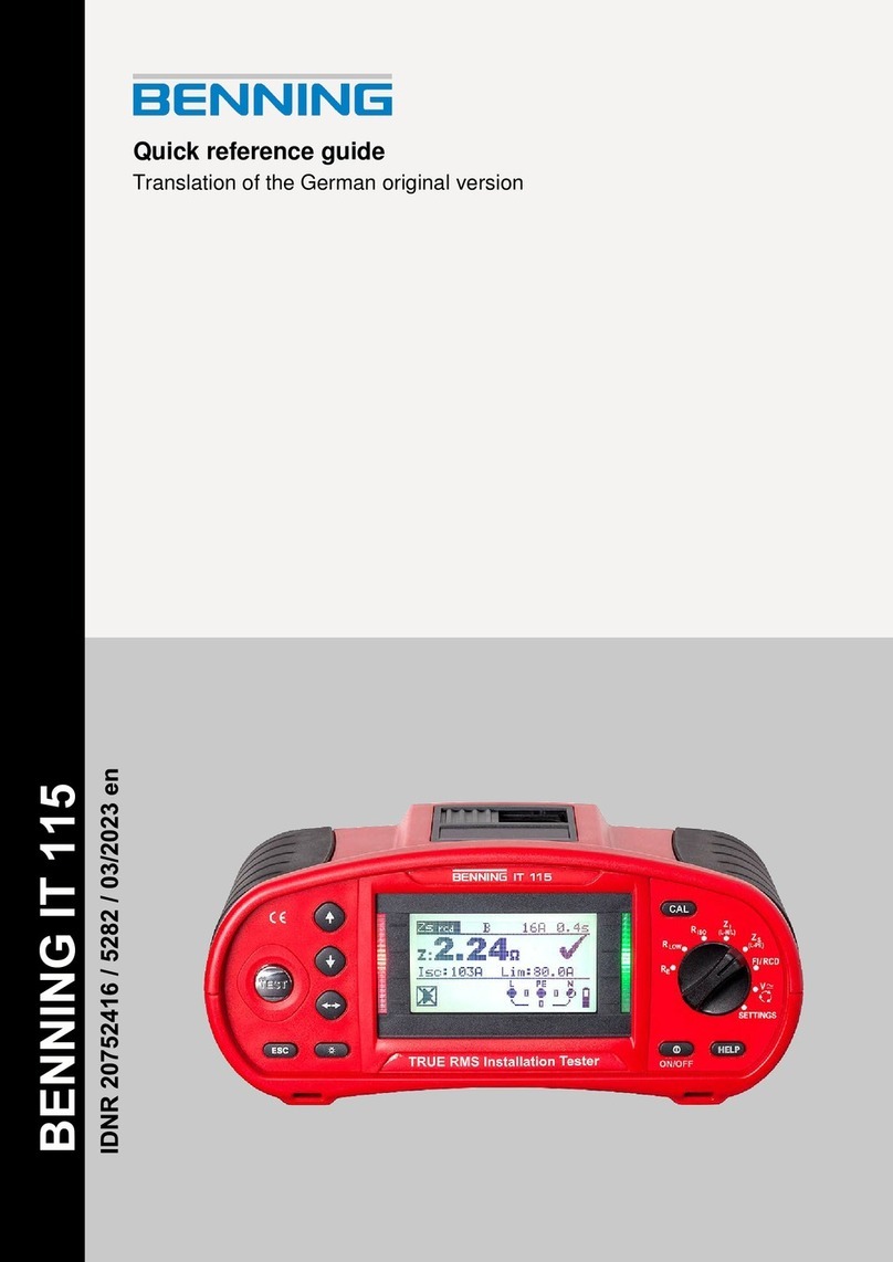
BENNING IT 115 Content
- 3 -
T ble of contents
1
Pref ce ............................................................................................................................... 5
2
S fety nd oper ting instructions ................................................................................... 6
2.1
Warnings ..................................................................................................................... 6
2.2
Batteries / storage batteries and charger ................................................................... 10
2.3
Standards applied ..................................................................................................... 12
3
Device description .......................................................................................................... 13
3.1
Front panel ................................................................................................................ 13
3.2
Connection panel ...................................................................................................... 14
3.3
Rear panel ................................................................................................................ 15
3.4
Carrying the installation tester ................................................................................... 16
3.4.1
Attachment of the carrying strap ........................................................................ 17
3.5
Scope of delivery and optional accessories ............................................................... 18
3.5.1
Standard scope of delivery ................................................................................ 18
3.5.2
Optional accessories ......................................................................................... 18
4
Oper ting the BENNING IT 115 inst ll tion tester ........................................................ 19
4.1
Indications and acoustic warning signals ................................................................... 19
4.1.1
onnection monitor ........................................................................................... 19
4.1.2
Battery indication ............................................................................................... 19
4.1.3
Warnings and messages ................................................................................... 19
4.1.4
Evaluation field .................................................................................................. 20
4.1.5
Acoustic warning signals ................................................................................... 20
4.1.6
Help menu ("HELP" key) ................................................................................... 21
4.1.7
Background lighting and contrast ....................................................................... 21
4.2
Function selector switch ............................................................................................ 22
4.3
"SETTINGS" mode .................................................................................................... 23
4.3.1
Language .......................................................................................................... 23
4.3.2
R D testing ....................................................................................................... 23
4.3.3
Isc factor (scaling factor) .................................................................................... 25
4.3.4
ommander ON/OFF ........................................................................................ 25
4.3.5
Initial settings ..................................................................................................... 26
5
Me surements ................................................................................................................. 28
5.1
TRMS voltage, frequency and phase sequence ........................................................ 28
5.2
Insulating resistance.................................................................................................. 30
5.3
Low-impedance resistance / continuity test ............................................................... 32
5.3.1
Low-impedance resistance with a testing current of 200 mA ............................. 32
5.3.2
ontinuity test with a testing current of 7 mA ..................................................... 33
5.3.3
ompensation (null balance) of the test cable resistance .................................. 34
5.4
RCD testing ............................................................................................................... 36
5.4.1
ontact voltage (Uc) .......................................................................................... 37
5.4.2
Tripping time (R Dt) .......................................................................................... 38
5.4.3
Tripping current (R D I) .................................................................................... 38
5.4.4
Automatic test .................................................................................................... 39
5.5
Loop impedance and prospective short-circuit current ............................................... 41
5.6
Line impedance and prospective short-circuit current / voltage drop ......................... 43
5.6.1
Line impedance and prospective short-circuit current ........................................ 44
5.6.2
Voltage drop ...................................................................................................... 45
5.7
Earthing resistance ................................................................................................... 47


