Amphenol Temposonics M Series User manual

Document Part No.
551132 Revision B
User’s Manual
M-Series
Analogue/PWM Tester
Magnetostrictive Linear Position Sensors
Temposonics®
Absolute, Non-Contact Position Sensors
M-Series
Analogue/PWM Tester
User’s Manual
Document Part Number
551132 Revision B

MTS Sensors
M-Series Tester
User’s Manual
Content
1 The M-Series analogue/PWM Test Kit
1.1 Contents and accessories
1.2 Familiarizing yourself with the M-Series Tester
1.2.1 Front panel
1.2.2 Top panel
2 Installation
2.1 Connecting analogue sensors
2.2 Connecting PWM sensors
2.3 Battery charger setup
2.4 AC power plug
2.5 Quick start instruction label
2.6 Carrier handle adjustment
3 Operation
3.1 Startup
3.2 Mode selection
3.2.1 Voltage (Volt)
3.2.2 Current (Curr)
3.2.3 Battery level (Batt)
3.2.4 Battery charging
3.2.5 Scaled PWM (Puum)
3.2.6 PWM time of flight (TOF)
3.3 Verification
3.4 Troubleshooting
I2I

I3IMTS Sensors
1. The M-Series analogue/PWM Test Kit
The M-Series analogue/PWM Tester supports analogue, 0 - 20 mA and 0 - 10 Vdc, scaled Pulse Width Modulated (PWM), and PWM time of flight (tof) sensor out-
puts. The M-Series Tester is a battery powered device that can be used in test bench and field applications to verify that the MTS Sensor is functioning properly and
is producing the appropriate signal outputs.
• Easy connection to MTS’ M12 integrated connector system
• Easy to use push-button controls
• Supports voltage (0-10 Vdc) and current (0-20 mA) outputs
• Tolerances 5 Vdc – 10 mV, 20 mA – 0,02 mA
• Supports scaled PWM and time-of-flight PWM outputs
• Compact construction for use in field applications
• Provides both +5 Vdc and +12/24 Vdc sensor power supply
• Battery that provides up to 8 hours of operation per charge
• Battery level monitoring
• Automatic detection of PWM sensor frequency
• Carrying case
1.1 Content and Accessories
The M-Series analogue/PWM Test Kit includes:
1. M-Series analogue/PWM Tester (254 025)
2. 12 VDC battery charger with adapter EU/UK (380 090)
3. Cable with MTS’ M12*1 integrated connector system and banana plugs pin 2-3-4 (253 869) for pin assignment E
4. Cable with MTS M12*1 integrated connector system and banana plugs pin 1-3-4, pin 1-3-2 (254 204) for pin assignment and H
5. Pigtailed cables with banana plugs (253 870) (not pictured)
6. Carrying case (590 138)
7. User’s uide (not pictured)
7. Quick start instruction label (not pictured)
Accessories
Power Plug Adapter
North America
Part No. 370573
Power Plug Adapter
Europe
Part No. 370572
Power Plug Adapter
United Kingdom
Part No. 370574
M-Series Tester
User’s Manual
12
6
3/4

1. The M-Series analogue/PWM Test Kit (continued)
1.2 Familiarizing yourself with the M-Series Tester
1.2.1 Front panel
1. CD panel
Tester LCD panel displays sensor output, settings, and battery level
2. Power switch
Toggle to turn the M-Series Tester ‘ON’ and ‘OFF’.
3. Mode button (A)
Press to change transducer modes and to reset system.
4. Special function button (B)
Press to change recirculation values in PWM TOF mode
1.2.2 Top Panel
1. Charger port
Port used to charge the battery
2. +5 V
Sensor 5 volt supply connection (Not an input port)
3. +12 V
Sensor 12 volt supply connection (Not an input port)
4. GND
Sensor ground connection.
5. ANA
Connection for sensors with analogue output signal.
6. PWM
Connection for sensors with PWM/TOF output signal.
MTS Sensors I4I
2
1
4
3
−−
++
−−
++
+5V
PWM
ANA
GND
+12V
M-Series Tester
User’s Manual
2456
1
3

I5IMTS Sensors
2. Installation
2.1 Connecting an analogue Sensor
To connect an analogue sensor equipped with MTS’ M12 integrated connector system to the M-Series Tester use the following procedure:
1. Use the provided cabling fitted with the M12 connector and connect the M12 cable to the MTS M12 integrated connector system on the sensor or cylinder.
Please pay attention to the pin assignment of the sensors. Sensors with pin assignment 2-3-4 (e.g. N10E) have to be connected with the M12*1 cable with the
connector colours brown, white and green. For sensors with pin assignment 1-2-3 (N10H) or 1-3-4 (N10 ) please us the cable with the connector colours black,
white and green.
(continue with step 3 below) OR
To connect an analogue sensor not equipped with MTS’ M12 integrated connector system:
1. Use the Pigtailed cable that is included in the test kit to connect the ends without banana plugs to the customer’s specified interface/connector that mates to the
M-Series sensor or cylinder.
2. Ensure that the wire colors of the cable correspond with the wire colors of the output wires from the sensor.
3. Plug the brown banana plug into the +12 Vdc or +5 Vdc (depending on voltage required by the sensor) terminal on the top of the tester.
4. Plug the white banana plug into the DC ND terminal on the top of the tester.
5. Plug the green banana plug into the analog terminal at the top of the tester.
−−
+
+
−−
+
+
+5V
PWM
ANA
GND
+12V
Green
White
Black / Brown
M12 Cable Assembly
Select sensor
supply voltage
(+12 V or +5 V)
Attention! Please take care of the sensor type.
Select sensor
supply voltage
(+12 V or +5 V)
CUSTOMER
SPECIFIED
INTERFACE/
CONNECTOR
−
−
+
+
−
−
+
+
+5V
PWM
ANA
GND
+12V
White
Green
Brown
White
Green
Brown
White
Green
Brown
Sensor cable
Pigtail cable
assembly
M-Series Tester
User’s Manual

MTS Sensors I6I
−
−
++
−
−
++
+5V
PWM
ANA
GND
+12V
Green
White
Brown
M12 Cable Assembly
Select sensor
supply voltage
(+12 V or +5 V)
2. Installation (continued)
2.2 Connecting PWM Sensors
To connect a PWM sensor equipped with MTS’ M12 integrated connector system to the M-Series Tester use the following procedure:
1. Use the provided cabling fitted with the M12 connector and connect the M12 cable to the MTS M12 integrated connector system on the sensor or cylinder.
(continue with step 3 below) OR
To connect a PWM sensor not equipped with MTS’ M12 integrated connector system:
1. Use the Pigtailed cable that is included in the test kit to connect the ends without banana plugs to the customer’s specified interface/connector that mates to the
M-Series sensor or cylinder.
2. Ensure that the wire colors of the cable correspond with the wire colors of the output wires from the sensor.
3. Plug the brown banana plug into the +12 Vdc or +5 Vdc (depending on voltage required by the sensor) terminal on the top of the tester.
4. Plug the white banana plug into the DC ND terminal on the top of the tester.
5. Plug the green banana plug into the PWM terminal at the top of the tester.
M-Series Tester
User’s Manual
Select sensor
supply voltage
(+12V or +5V)
CUSTOMER
SPECIFIED
INTERFACE/
CONNECTOR
−−
++
−−
++
+5V
PWM
ANA
GND
+12V
White
Green
Brown
White
Green
Brown
White
Green
Brown
Sensor cable
Pigtail cable
assembly

MTS SensorsI7I
2. Installation (continued)
2.3 Battery Charger
The M-Series tester will also run off AC power supplied by the charger included in the test kit. To run the box of AC power or to charge the battery plug the charger
barrel plug into the charger port on the top of the test box and connect the charger to an AC Outlet.
2.4 AC Power Plug Adapter Connection / Replacement
The kits battery charger can be used on both 110 Vdc and 230 Vdc systems. For this reason, additional AC power plug adapters can be purchased (see
Accessories).
Use the following steps to change the power plug adapter:
1. Unplug the AC adapter from the wall and from the M-Series Tester. Firmly hold the AC adapter in one hand with the plug facing you.
2. With the other hand, press down on the plug adapter and slide upwards away from you.
To replace the AC power plug adapter:
1. Chose the correct adapter.
2. Slide the adapter plug against the adapter (There are grooves along the
channel for the adapter plug). Slide the adapter down until it snaps into place
2.5 Quick Start Instruction abel
A quick start instruction label is included in the test kit. The label is designed to fit flush on the backside of the M-Series analogue/PWM Tester.
• Remove dust and dirt from the surface of the backside.
• Align and apply the label smoothly on the backside of the tester and apply the label smoothly.
−
−
++
−
−
++
+5V
PWM
ANA
GND
+12V
Note:
There is an arrow on the adapter to denote the way to slide the plug during
removal.
M-Series Tester
User’s Manual

MTS Sensors I8I
2. Installation (continued)
2.6 Carrier Handle Adjustment
To adjust the position of the carrier handle of the tester, please press and hold both buttons on the side of the handle at the same time. Adjust the position of the
handle. After the adjustment release the buttons.
3. Operation
3.1 Start-Up
Perform the following start-up procedure:
1. Turn the tester power switch to the ‘ON’ position. The test box display will now
cycle through the startup display sequence:
a) LED test for 1 second
b) Software Data test 1 second
c) Currently active Mode for 5 seconds
The default mode setting is configured for voltage at the factory, but after the initial use, the tester will start up in the last mode the tester was set to.
2. If required, change the mode by pushing the ‘A’ button. (see 3.2 Mode Selections).
3. Repeat step 2 until the appropriate mode is selected and seen on the display.
3.2 Mode Selections
3.2.1 Voltage (Volt)
The voltage range will be displayed in Volts for the M-Series sensor with voltage output. It will depend on the sensor model selected.
Note:
1. The tester switch is in the ‘ON’ position when the red LED is lit.
2. If the LED on the power switch is not lit, the device might be in low power
mode and the power supply needs to be connected to the charger port on
the top of the tester.
Mode Display Unit
Voltage Volt Volts
Current Curr Milliamps (mA)
Battery Batt Display battery voltage
PWM Puum % of Display
TOF tOF Millimeters (mm)
M-Series Tester
User’s Manual

MTS SensorsI9I
3. Operations (continued)
3.2.2 Current (Curr)
The current range will be displayed in Milliamps for M-Series sensor with current output. The current range shown will depend on the sensor model selected.
3.2.3 Battery evel (bAtt)
The M-Series tester utilizes a battery to power both the charger and the sensor.
The M-Series Tester contains circuitry that continually measures the device
battery level to ensure that the necessary voltage is available to power the
sensor. If the battery level drops below 9 volts, the tester will not have the
power to energize most M-Series sensors.
Some M-Series model sensor only require a 5 volt supply and for these transdu-
cers test box battery voltage levels lower than 5 volts will interrupt sensor output.
Low battery (LOBA)
If ‘LOBA’ (Low Battery) displays, connect the 12 volt power adapter to the charger port. Whenever the internal battery is allowed to discharge below 1.8 volts, the
device will enter low power mode. In the event the device enters low power mode, connect the supply voltage to the charger port and cycle the power. When the
battery level drops below 1.8 volts there is not enough voltage to drive the internal circuitry of the M-Series Tester.
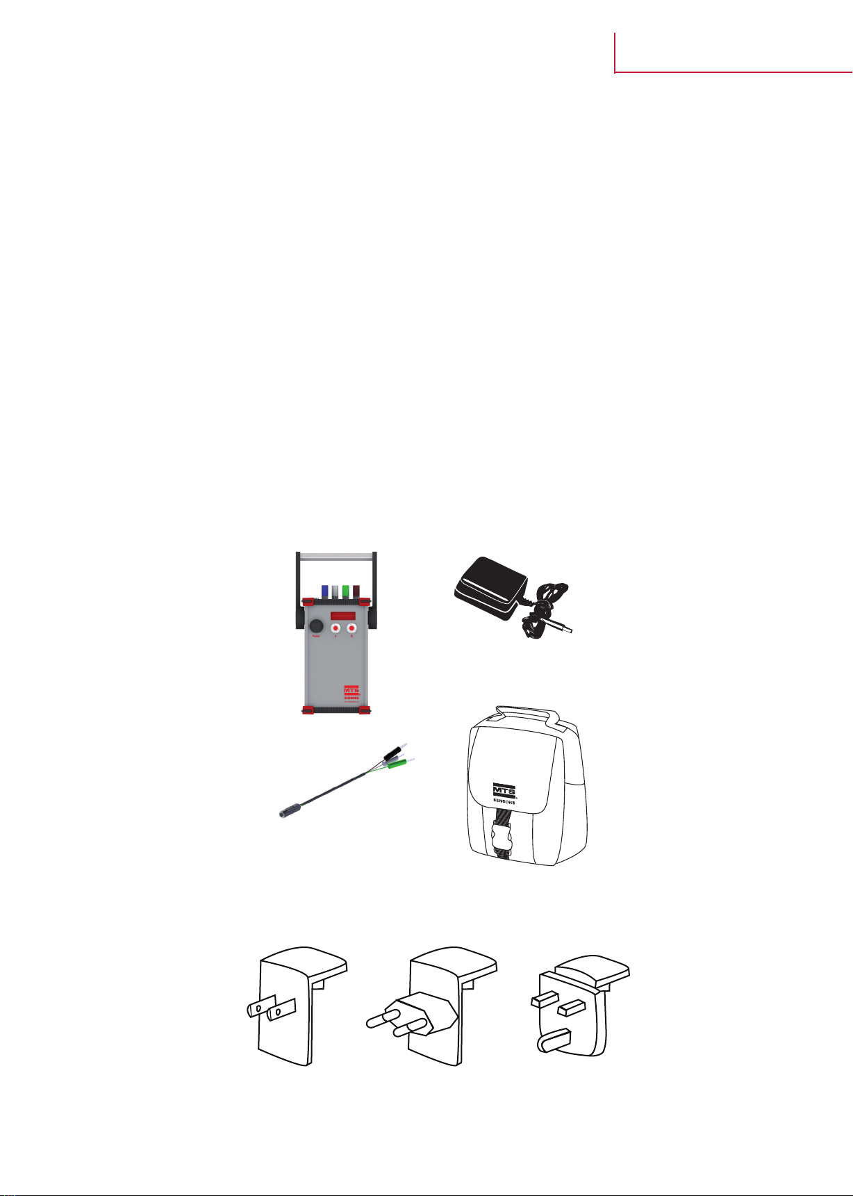
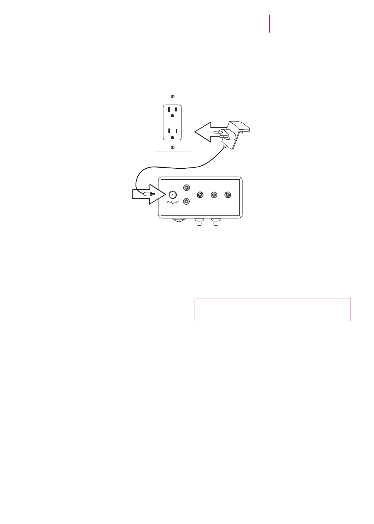
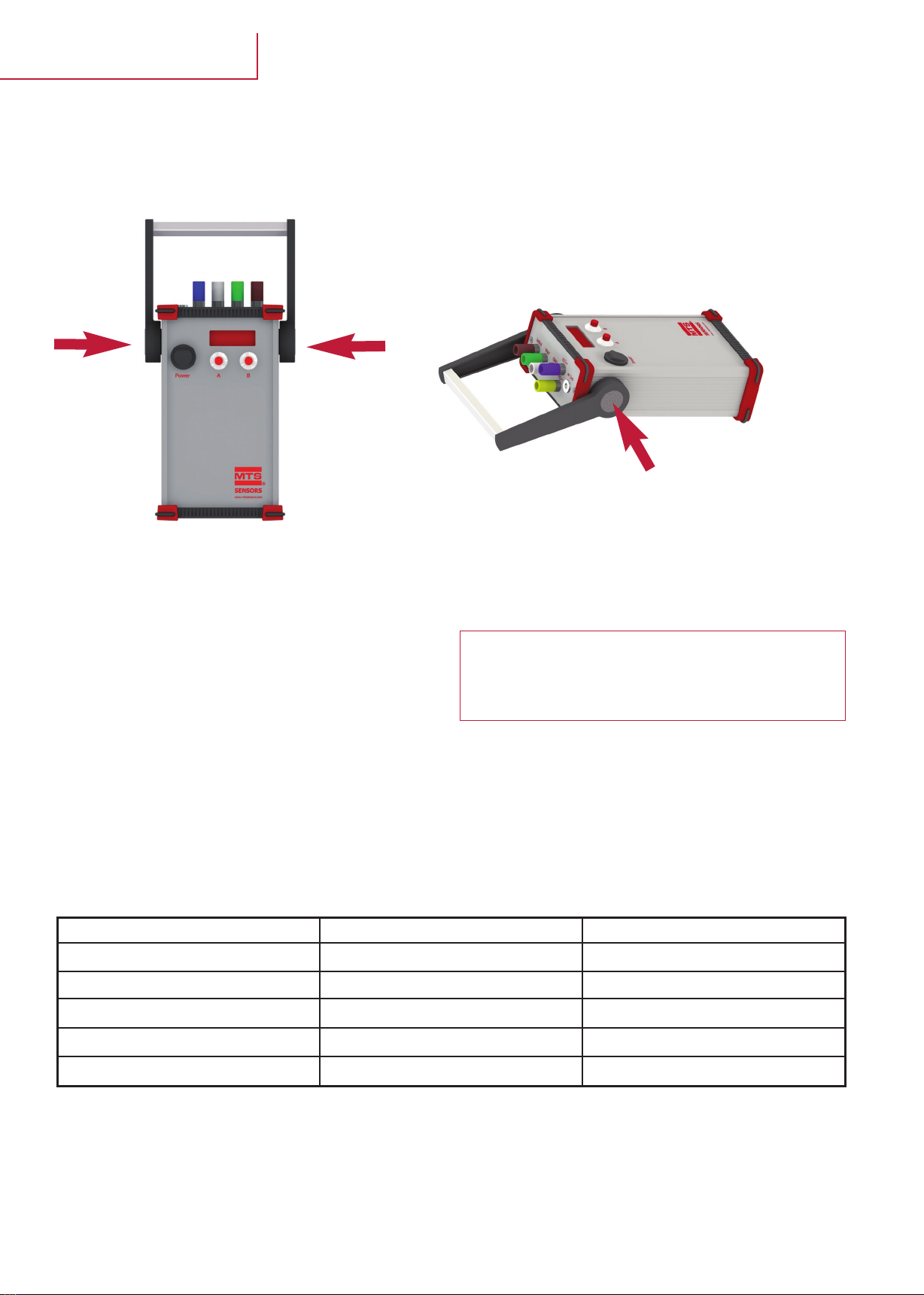
3.2.4 Battery Charging
To recharge the battery of the M-Series Tester, connect the supplied AC power
plug adapter to the charger port on the top of the device. The LED indicator on
the charger will indicate the state of the charging process. The smart charger
that is included in the M-Series Tester Kit will give the battery a quick charge
first and then apply a constant float charge to maintain battery level.
3.2.5 Scaled PWM (Puum)
Configuring the M-Series Tester to PWM mode will allow the output of the scaled PWM sensor to be displayed.
The M-Series Tester will initially show the frequency of the attached scaled PWM sensor output. This will be displayed for 2 seconds before switching the display to
the sensor output range.
The scaled PWM sensor output will display the sensor position as a % of the full stroke length. At the zero position the “zero percent”-value for the attached sensor
will be displayed. At the full stroke position the “full scale percent”-value for the attached sensor will be displayed.
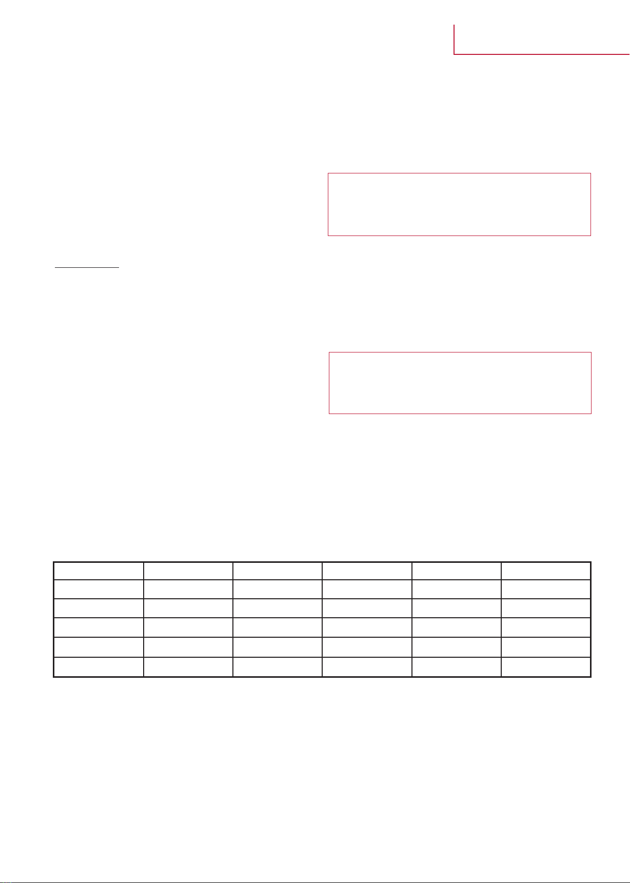
Example readings for the various sensor types:
To view the frequency of the scaled PWM sensor:
1. Press the ‚A’ button once.
2. Frequency will display for 1 second after “puum” for the current mode is displayed.
Warning:
Only use the supplied 12 volts adapter to charge the M-Series Tester. Using an
off the shelf AC adapter without smart charging capabilities can result in over-
charging the internal Sealed Lead Acid (SLA) batteries. Overcharging the batte-
ries could lead to overheating and damage to the battery cells.
PWM Sensor Type % at Zero Position % at 1/4 stroke % at 1/2 stroke % at 3/4 stroke % at full stroke
5 % - 95 % 5 % 27,5 % 50 % 72,5 % 95 %
10% - 90 % 10 % 30 % 50 % 70 % 90 %
15 % - 85 % 15 % 32,5 % 50 % 67,5 % 85 %
20 % - 80 % 20 % 35 % 50 % 65 % 80 %
25 % - 75 % 25 % 37,5 % 50 % 62,5 % 75 %
M-Series Tester
User’s Manual
Note:
1. See sensor model specification to determine what supply voltage is needed.
2. The LOBA (Low Battery) status alert will disrupt the output readings of the
sensor every 60 seconds for 3 seconds until the power adapter is connected
to the tester via the charger port.

MTS Sensors I10 I
3. Operations (continued)
3.2.6 PWM Time of Flight (TOF)
Time of Flight mode allows for the M-Series Tester to display the output of a PWM
ToF sensor. In a PWM ToF sensor the displacement amount is determined by the
time between the creation of the interrogation pulse an the
detection of the return pulse in the sensing element. This ToF calculation is depen-
dent on the velocity of the return pulse, sensor length, and the number
of recirculations performed by the sensor.
Recirculations:
When the M-Series Tester is in TOF-Mode, the tOF name on the display is followed by a hexadecimal value (0-F) which indicates the number of recirculations expec-
ted from the attached sensor. The default hexadecimal value for the mode is 0. The number of recirculations can be changed to accommodate the attached sensor
output.
Perform the steps below to reset the number of recirculations:
1. When ‘tOF’ displays on the screen, press and hold the ‘B’ button for 2 seconds.
2. The recirculation character (0-F) will begin to blink.
3. When the character is blinking:
Press „B“ button to change the value. Repeat the procedure until the appropriate value displays. Then, press the ‘A’ button to return to the “tOF” measurement
mode.
Note:
In order to display millimeters a fixed value has been used for the location of
the null with respect to the sensing element. The M-Series Tester is setup for
the standard offset in the model MH and MS sensors. For all other models
there may be a shift in the output reading due to mechanical differences from
the MH and MS models. Please check with the factory for the offset on other
M-Series sensor models.
Note:
Once the ‘A’ button is pressed the desired recirculation value is saved in the
memory.
Display Values Recirculations
tOF0 0
tOF1 1
tOF2 2
tOF3 3
tOF4 4
tOF5 5
tOF6 6
tOF7 7
tOF8 8
tOF9 9
tOFA 10
tOFb 11
tOFC 12
tOFd 13
tOFE 14
tOFF 15
Note:
1. ‘T0F0’ denotes that there are no recirculations only the initial interrogation
pulse.
2. In the PWM TOF mode if the reported displacement is longer than 4 digits
the display will blink and only the most significant digits will be displayed.
M-Series Tester
User’s Manual

MTS SensorsI11 I
3. Operations (continued)
3.3 Verification
Verify the sensor is reading the displacement of the magnet by moving the
magnet in the bench test of the attached sensor or by stroking the cylinder.
Observe the change in output reading.
3.4 Troubleshooting
No Power
1. Confirm the power switch is in ‘ON’ position
2. M-Series Tester my be in Low Power Mode
3. Plug in AC Power adapter and check the battery level
The sensor readings aren’t showing on the display
1. Is the M-Series Tester in the correct mode?
2. Ìs the M-Series battery level above 9 Vdc?
3. Is the sensor connected to the appropriate terminals?
Error Message ‘[--]’ is seen in PWM od PWM TOF mode
1. Make sure the correct plug is in the PWM port at the top of the M-Serie Tester
2. If in TOF mode, make sure the correct number or recirculations is selected
3. Check battery level to ensure the unit is providing a minimum of 9 Vdc to sensor
Note:
The M-Series Tester is not a calibrated device and should only be used for indi-
cation purpose only. The M-Series Tester is designed to be used to verify that
the sensor is functional after cylinder assembly and as a field troubleshooting
device. For field troubleshooting the tester is designed to isolate the sensor
from the rest of the vehicle in order to independently verify sensor functionality.
M-Series Tester
User’s Manual

UNITED STATES
Temposonics, LLC
Americas & APAC Region
3001 Sheldon Drive
Cary, N.C. 27513
Phone: +1 919 677-0100
E-mail: [email protected]
GERMANY
Temposonics
GmbH & Co. KG
EMEA Region & India
Auf dem Schüffel 9
58513 Lüdenscheid
Phone: +49 2351 9587-0
E-mail: [email protected]
ITALY
Branch Ofce
Phone: +39 030 988 3819
E-mail: [email protected]
FRANCE
Branch Ofce
Phone: +33 6 14 060 728
E-mail: [email protected]
UK
Branch Ofce
Phone: +44 79 44 15 03 00
E-mail: [email protected]
SCANDINAVIA
Branch Ofce
Phone: + 46 70 29 91 281
E-mail: [email protected]
CHINA
Branch Ofce
Phone: +86 21 2415 1000 / 2415 1001
E-mail: [email protected]
JAPAN
Branch Ofce
Phone: +81 3 6416 1063
E-mail: [email protected]
temposonics.com
© 2021 Temposonics, LLC – all rights reserved. Temposonics, LLC and Temposonics GmbH & Co. KG are subsidiaries of Amphenol Corporation. Except for any third party marks for
which attribution is provided herein, the company names and product names used in this document may be the registered trademarks or unregistered trademarks of Temposonics, LLC or
Temposonics GmbH & Co. KG. Detailed trademark ownership information is available at www.temposonics.com/trademarkownership.
Document Part Number:
551132 Revision B (EN)
This manual suits for next models
1
Table of contents
Popular Test Equipment manuals by other brands

PairGain
PairGain PG-Flex FSU-796 List 4 FPI Streaker Card Quick installation guide

WAGNER
WAGNER L722 owner's manual

Desco
Desco 19276 Installation, operation and maintenance

Presys
Presys T-350P Technical manual

PCB Piezotronics
PCB Piezotronics Modular Series Installation and operating manual

Triplett
Triplett CHEK-A-CELL instruction manual