SENTRONIC M-SYSTEM M2MNV User manual
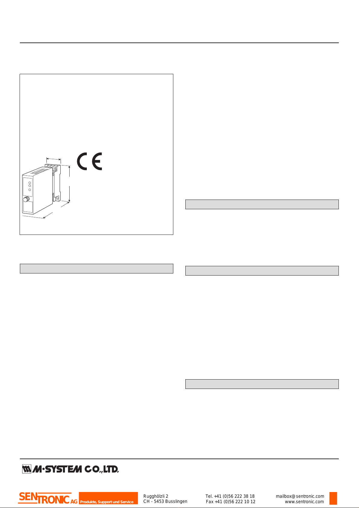
MODEL: M2MNV
Super-mini Signal Conditioners Mini-M Series
ANALOG SWITCHING MODULE
Functions & Features
• Switches between two analog signal channels
• Switches/Distributes one voltage signal to two channels
• CE marking
Typical Applications
• Switching 1 – 5V DC signal: no contact failure that
happens when using mechanical contacts for this purpose
• Switching low-speed pulse signals
Model
29.5 (1.16)
76
(2.99)
mm (inch)
124
(4.88)
MODEL: M2MNV-[1][2]-[3][4]
ORDERING INFORMATION
• Code number: M2MNV-[1][2]-[3][4]
Specify a code from below for each [1] through [4].
(e.g. M2MNV-11-M2/CE/Q)
• Specify the specification for option code /Q
(e.g. /C01/S01)
Note: Must be used with its socket. NOT installable to a
multi-unit installation base. (e.g. model: M2BS-16)
[1] SWITCHING CONTROL
1: Interlocking switching control (single-pole contact)
2: Independent switching control (double-pole contact)
[2] INPUT
1: Current signal (no receiving resistor)
2: Current signal (receiving resistor 50 Ω)
3: Voltage signal
[3] POWER INPUT
AC Power
M: 85 – 264 V AC (Operational voltage range 85 – 264 V,
47 – 66 Hz)
(Select ‘/N’ for ‘Standards & Approvals’ code.)
M2: 100 – 240 V AC (Operational voltage range 85 – 264 V,
47 – 66 Hz)
DC Power
R: 24 V DC
(Operational voltage range 24 V ±10 %, ripple 10 %p-p max.)
R2: 11 – 27 V DC
(Operational voltage range 11 – 27 V, ripple 10 %p-p max.)
(Select ‘/N’ for ‘Standards & Approvals’ code.)
P: 110 V DC
(Operational voltage range 85 – 150 V, ripple 10 %p-p max.)
[4] OPTIONS (multiple selections)
Standards & Approvlas (must be specified)
/N: Without CE
/CE: CE marking
Other Options
blank: none
/Q: Option other than the above (specify the specification)
SPECIFICATIONS OF OPTION: Q (multiple selections)
COATING (For the detail, refer to M-System's web site.)
/C01: Silicone coating
/C02: Polyurethane coating
/C03: Rubber coating
TERMINAL SCREW MATERIAL
/S01: Stainless steel
GENERAL SPECIFICATIONS
Construction: Plug-in
Connection: M3 screw terminals (torque 0.8 N·m)
Housing material: Flame-resistant resin (black)
Switching: Photo MOS relay
Isolation: Signal channel to switching command contact to
power
Power indicator LED: Green light turns on when the power is
supplied.
Status indicator LED 1: Green light turns on when the signal
channel 1 (A1-B1) is alive.
Status indicator LED 2: Green light turns on when the signal
channel 2 (A2-B1) is alive.
INPUT & OUTPUT
■ Signal Channels
Max. operational voltage range: ±50 V DC (min. span 10
mV)
Max. operational current range: ±50 mA DC (min. span 1
mA)
Receiving resistor: 50 Ω incorporated (input code 2)
ON resistance: ≤ 50 Ω per wire
(ON resistance of photo MOS relay)
Rugghölzli 2
CH - 5453 Busslingen Tel.+41 (0)56 222 38 18
Fax +41 (0)56 222 10 12 mailbox@sentronic.com
www.sentronic.com
Produkte, Support und Service
SENTRONICAG
MODEL: M2MNV
■ Output
Current signal input (no receiving resistor):
Equal to the input signal
Current signal input (receiving resistor 50 Ω):
Voltage signal equal to [Current × 50 Ω]
Voltage signal input: Equal to the input signal
■ Switching Command: Relay or open collector
Contact detecting: 5 V DC / 1 mA
Detecting levels: ≤ 1 kΩ at ON / ≥ 10 kΩ at OFF
INSTALLATION
Power Consumption
•AC Power input:
Approx. 3 VA at 100 V
Approx. 4 VA at 200 V
Approx. 5 VA at 264 V
•DC power input: Approx. 2 W
Operating temperature: -5 to +55°C (23 to 131°F)
Operating humidity: 30 to 90 %RH (non-condensing)
Mounting: Surface or DIN rail
Weight: 150 g (0.33 lbs)
PERFORMANCE in percentage of span
Accuracy: ±0.1 % (input code 2)
Temp. coefficient: ±0.010 %/°C (±0.006 %/°F) (input code
2)
Switching response time: ≤ 5 msec.
Leakage current at open circuit: ≤ 1 μA
Line voltage effect: ±0.1 % over voltage range
Insulation resistance: ≥ 100 MΩ with 500 V DC
(signal channel to switching command contact to power)
Dielectric strength:
2000 V AC @1 minute
(switching command contact to power to ground)
2000 V AC @1 minute
(signal channel to power to ground)
1500 V AC @1 minute
(signal channel to switching command contact)
STANDARDS & APPROVALS
CE conformity:
EMC Directive (2004/108/EC)
EMI EN 61000-6-4: 2007
EMS EN 61000-6-2: 2005
Low Voltage Directive (2006/95/EC)
EN 61010-1: 2001
Installation Category II
Pollution Degree 2
Signal channel or switching command contact to power:
Reinforced insulation (300 V)
Signal channel to switching command contact: Basic
insulation (300 V)
Rugghölzli 2
CH - 5453 Busslingen Tel.+41 (0)56 222 38 18
Fax +41 (0)56 222 10 12 mailbox@sentronic.com
www.sentronic.com
Produkte, Support und Service
SENTRONICAG
MODEL: M2MNV
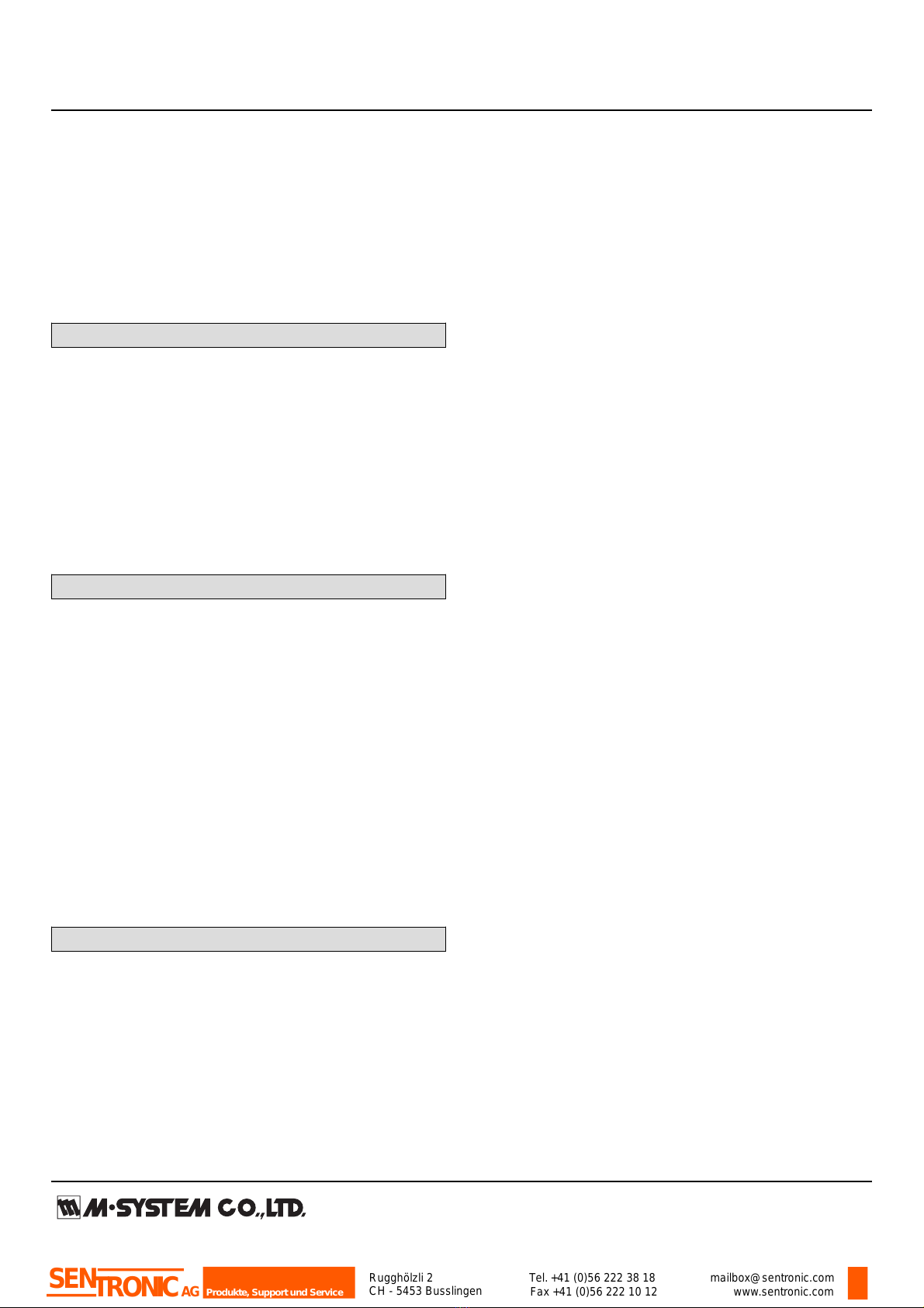
EXTERNAL VIEW
• Channel 2
Status LED 2
• Channel 1
Status LED 1
Power LED
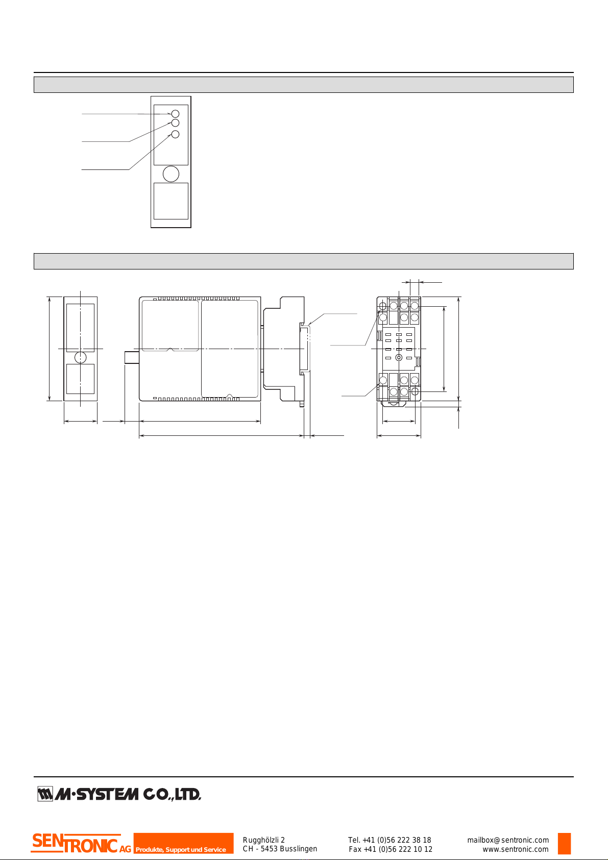
DIMENSIONS unit: mm (inch)
4
8 7
1011
56 123
9
22 (.87)
6 (.23)
59 (2.32)
11–M3
SCREW
72 (2.83)
29.5 (1.16)
2–4.2x5
(.17x.20)
MTG HOLE
6 (.24) deep
• When mounting, no extra space is needed between units.
21.5 (.85)
70.5 (2.78)
84 (3.31)10 (.39)
DIN RAIL
35mm wide
[4 (.16)]
114 (4.49)
4 (.16)
Rugghölzli 2
CH - 5453 Busslingen Tel.+41 (0)56 222 38 18
Fax +41 (0)56 222 10 12 mailbox@sentronic.com
www.sentronic.com
Produkte, Support und Service
SENTRONICAG
MODEL: M2MNV
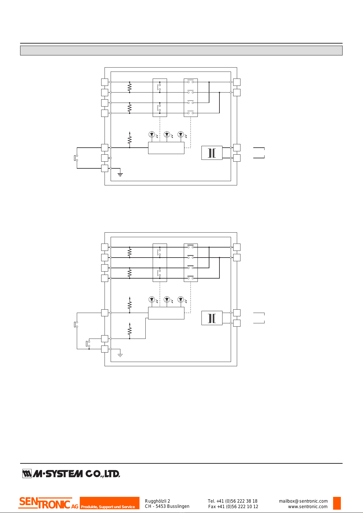
SCHEMATIC CIRCUITRY & CONNECTION DIAGRAM
Base Socket
1
3
7
8
2
6
9
SWITCHING
COMMAND SW1
4
5
50Ω
*1
*2
50Ω
*1
■INTERLOCKING SWITCHING CONTROL (single-pole contact)
Base Socket
1
3
7
8
2
6
9
SWITCHING
COMMAND
SW1
SW2
4
5
*1. Provided only with the input code 2: Current signal (receiving resistor 50Ω).
*2. Provided only with the input code 1: Current signal (no receiving resistor).
*1/*2 Not provided with the input code 3.
A1-B1 channel is connected when the SW1 is turned on (closed).
A2-B1 channel is connected when the SW2 is turned on (closed).
*1. Provided only with the input code 2: Current signal (receiving resistor 50Ω).
*2. Provided only with the input code 1: Current signal (no receiving resistor).
*1/*2 Not provided with the input code 3.
A1-B1 channel is connected when the SW1 is turned on (closed).
A2-B1 channel is connected when the SW1 is turned off (open).
50Ω
*1
50Ω
*1
■INDEPENDENT SWITCHING CONTROL (double-pole contact)
Photo MOSFET
Relay Driver
5k
Ω
5V
5k
Ω
5V
B1-1
B1-2
A1-1
A1-2
A2-1
A2-2
B1-1
B1-2
A1-1
A1-2
A2-1
A2-2
5k
Ω
5V
STATUS
LED 1
POWER
LED STATUS
LED 2
*2
Photo MOSFET
Relay Driver
STATUS
LED 1
POWER
LED STATUS
LED 2
U(+)
V(–) POWER
10
11
U(+)
V(–) POWER
10
11
Rugghölzli 2
CH - 5453 Busslingen Tel.+41 (0)56 222 38 18
Fax +41 (0)56 222 10 12 mailbox@sentronic.com
www.sentronic.com
Produkte, Support und Service
SENTRONICAG

MODEL: M2MNV
SWITCHING OPERATIONS
1
2
4
5
7
8
1
2
4
5
7
8
Current Signal (no receiving resistor)
Power : OFF
Switching command : OFF (open)
1
2
4
5
7
8
1
2
4
5
7
8
Power : ON
Switching command : OFF (open)
1
2
4
5
7
8
1
2
4
5
7
8
Power : ON
Switching command : ON (short)
Current Signal (receiving resistor 50Ω)
Voltage Signal
Current Signal (no receiving resistor)
Transition (ON to OFF, OFF to ON) Status
Power : ON
Switching command : OFF to ON
or
Power : ON
Switching command : ON to OFF
Current Signal (receiving resistor 50Ω)
Voltage Signal
*1. Resistor is provided only for the input code 2: Current signal (receiving resistor 50Ω).
*1. Resistor is provided only for the input code 2: Current signal (receiving resistor 50Ω).
*1
*1
*1
*1
1
2
4
5
7
8
1
2
4
5
7
8
*1
*1
*1
*1
• Switching Status
When the switching command contact is switched from
OFF to ON or from ON to OFF, the signal channel is
switched only after all photo MOS relays turn on
(closed).
When the switching command contact is switched from
OFF to ON or from ON to OFF, the signal channel is
switched only after all photo MOS relays turn off
(open).
■INTERLOCKING SWITCHING CONTROL (single-pole contact)
Single contact is used to switch from Signal Channel 1 (A1-B1) to Signal Channel 2 (A2-B1) and vice versa.
CHANNEL 1 (A1) CHANNEL 2 (A2)
Terminal 3 – 9 OFF (open) OFF ON
Terminal 3 – 9 ON (closed) ON OFF
Status LED turn on when the respective channels are alive.
■ INDEPENDENT SWITCHING CONTROL (double-pole contact)
Double contacts are used to independently switch Signal Channel 1 (A1-B1) and Signal Channel 2 (A2-B1).
CHANNEL 1 (A1) CHANNEL 2 (A2)
Terminal 3 – 9 OFF (open) OFF ----
Terminal 3 – 9 ON (closed) ON ----
Terminal 6 – 9 OFF (open) ---- OFF
Terminal 6 – 9 ON (closed) ---- ON
Status LED turn on when the respective channels are alive.
Rugghölzli 2
CH - 5453 Busslingen Tel.+41 (0)56 222 38 18
Fax +41 (0)56 222 10 12 mailbox@sentronic.com
www.sentronic.com
Produkte, Support und Service
SENTRONICAG

MODEL: M2MNV
Specifications are subject to change without notice.
Rugghölzli 2
CH - 5453 Busslingen Tel.+41 (0)56 222 38 18
Fax +41 (0)56 222 10 12 mailbox@sentronic.com
www.sentronic.com
Produkte, Support und Service
SENTRONICAG

M2MNV
P. 1 / 4EM-5095 Rev.1
ANALOG SWITCHING MODULE MODEL M2MNV
INSTRUCTION MANUAL
BEFORE USE ....
Thank you for choosing M-System. Before use, please check
contents of the package you received as outlined below.
If you have any problems or questions with the product,
please contact M-System’s Sales Office or representatives.
■ PACKAGE INCLUDES:
Signal conditioner (body + base socket) ...................... (1)
■ MODEL NO.
Confirm Model No. marking on the product to be exactly
what you ordered.
■ INSTRUCTION MANUAL
This manual describes necessary points of caution when
you use this product, including installation, connection and
basic maintenance procedures.
POINTS OF CAUTION
■ CONFORMITY WITH EC DIRECTIVES
• This equipment is suitable for use in a Pollution Degree
2 environment and in Installation Category II, with the
maximum operating voltage of 300V.
Basic insulation is maintained between signal channel
and switching command contact. Prior to installation,
check that the insulation class of this unit satisfies the
system requirements.
• Altitude up to 2000 meters
•The equipment must be mounted inside a panel.
• The equipment must be installed such that appropriate
clearance and creepage distances are maintained to con-
form to CE requirements. Failure to observe these re-
quirements may invalidate the CE conformance.
■ POWER INPUT RATING & OPERATIONAL RANGE
•Locate the power input rating marked on the product and
confirm its operational range as indicated below:
85 – 264V AC rating: 85 – 264V, 47 – 66 Hz, approx. 3 – 5VA
100 – 240V AC rating: 85 – 264V, 47 – 66 Hz, approx. 3 – 5VA
24V DC rating: 24V ±10%, approx. 2W
11 – 27V DC rating: 11 – 27V, approx. 2W
110V DC rating: 85 – 150V, approx. 2W
■ GENERAL PRECAUTIONS
• Before you remove the unit from its base socket or mount
it, turn off the power supply for safety.
■ ENVIRONMENT
• Indoor use
•When heavy dust or metal particles are present in the air,
install the unit inside proper housing with sufficient ven-
tilation.
• Do not install the unit where it is subjected to continuous
vibration. Do not subject the unit to physical impact.
• Environmental temperature must be within -5 to +55°C
(23 to 131°F) with relative humidity within 30 to 90% RH
in order to ensure adequate life span and operation.
• Be sure that the ventilation slits are not covered with ca-
bles, etc.
■ WIRING
• Do not install cables (power supply, signal line and switch-
ing command contact) close to noise sources (relay drive
cable, high frequency line, etc.).
• Do not bind these cables together with those in which
noises are present. Do not install them in the same duct.
■ AND ....
• The unit is designed to function as soon as power is sup-
plied, however, a warm up for 10 minutes is required for
satisfying complete performance described in the data
sheet.
COMPONENT IDENTIFICATION
■ FRONT PANEL CONFIGURATION
Body Base Socket
Fixing Screw
Connection
Diagram
Specifications
Model
• Channel 2
Status LED 2
• Channel 1
Status LED 1
Power LED
Rugghölzli 2
CH - 5453 Busslingen Tel.+41 (0)56 222 38 18
Fax +41 (0)56 222 10 12 mailbox@sentronic.com
www.sentronic.com
Produkte, Support und Service
SENTRONICAG
M2MNV
P. 2 / 4EM-5095 Rev.1
INSTALLATION
Loosen the fixing screw at the front of the unit in order to separate the body from the base socket.
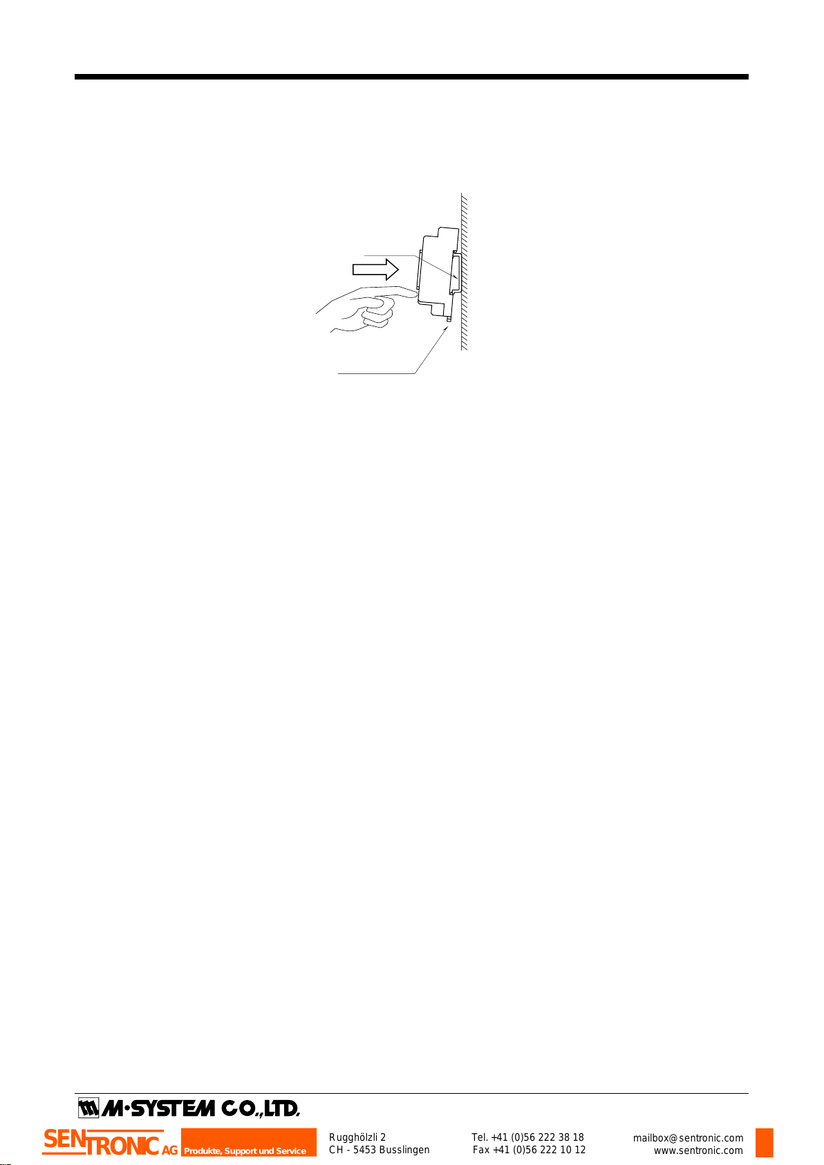
■ DIN RAIL MOUNTING
Set the base socket so that its DIN rail adaptor is at the bottom. Position the upper hook at the rear side of base socket on
the DIN rail and push in the lower. When removing the socket, push down the DIN rail adaptor utilizing a minus screwdriver
and pull.
■ WALL MOUNTING
Refer to “EXTERNAL DIMENSIONS.”
DIN Rail
35mm wide
Spring Loaded
DIN Rail Adaptor
Rugghölzli 2
CH - 5453 Busslingen Tel.+41 (0)56 222 38 18
Fax +41 (0)56 222 10 12 mailbox@sentronic.com
www.sentronic.com
Produkte, Support und Service
SENTRONICAG

M2MNV
P. 3 / 4EM-5095 Rev.1
■ INTERLOCKING SWITCHING CONTROL (single-pole contact)
Single contact is used to switch from Signal Channel 1 (A1-B1) to Signal Channel 2 (A2-B1) and vice versa.
CHANNEL 1 (A1) CHANNEL 2 (A2)
Terminal 3 – 9 OFF (open) OFF ON
Terminal 3 – 9 ON (closed) ON OFF
Status LED turn on when the respective channels are alive.
■ INDEPENDENT SWITCHING CONTROL (double-pole contact)
Double contacts are used to independently switch Signal Channel 1 (A1-B1) and Signal Channel 2 (A2-B1).
CHANNEL 1 (A1) CHANNEL 2 (A2)
Terminal 3 – 9 OFF (open) OFF ----
Terminal 3 – 9 ON (closed) ON ----
Terminal 6 – 9 OFF (open) ---- OFF
Terminal 6 – 9 ON (closed) ---- ON
Status LED turn on when the respective channels are alive.
1
2
4
5
7
8
1
2
4
5
7
8
Current Signal (no receiving resistor)
Power : OFF
Switching command : OFF (open)
1
2
4
5
7
8
1
2
4
5
7
8
Power : ON
Switching command : OFF (open)
1
2
4
5
7
8
1
2
4
5
7
8
Power : ON
Switching command : ON (short)
Current Signal (receiving resistor 50Ω)
Voltage Signal
Current Signal (no receiving resistor)
Transition (ON to OFF, OFF to ON) Status
Power : ON
Switching command : OFF to ON
or
Power : ON
Switching command : ON to OFF
Current Signal (receiving resistor 50Ω)
Voltage Signal
*1. Resistor is provided only for the input code 2: Current signal (receiving resistor 50Ω).
*1. Resistor is provided only for the input code 2: Current signal (receiving resistor 50Ω).
*1
*1
*1
*1
1
2
4
5
7
8
1
2
4
5
7
8
*1
*1
*1
*1
• Switching Status
When the switching command contact is switched from
OFF to ON or from ON to OFF, the signal channel is
switched only after all photo MOS relays turn on
(closed).
When the switching command contact is switched from
OFF to ON or from ON to OFF, the signal channel is
switched only after all photo MOS relays turn off
(open).
SWITCHING OPERATIONS
Rugghölzli 2
CH - 5453 Busslingen Tel.+41 (0)56 222 38 18
Fax +41 (0)56 222 10 12 mailbox@sentronic.com
www.sentronic.com
Produkte, Support und Service
SENTRONICAG

M2MNV
CHECKING
1) Terminal wiring: Check that all cables are correctly con-
nected according to the connection diagram.
2) Power input voltage: Check voltage across the terminal
10 – 11 with a multimeter.
3) Switching command contact: Confirm adequate opera-
tions of the contact signal.
TERMINAL CONNECTIONS
Connect the unit as in the diagram below or refer to the con-
nection diagram on the side of the unit.
U(+)
V(–) POWER
10
11
1 7
82
4
5
B1-1
B1-2
A1-1
A1-2
A2-1
A2-2
3
6
9
SWITCHING
COMMAND SW1
■INTERLOCKING SWITCHING CONTROL
(single-pole contact)
U(+)
V(–) POWER
10
11
1 7
82
4
5
B1-1
B1-2
A1-1
A1-2
A2-1
A2-2
3
6
9
SWITCHING
COMMAND SW1
■INDEPENDENT SWITCHING CONTROL
(double-pole contact)
SW2
EXTERNAL DIMENSIONS unit: mm (inch)
4
8 7
1011
56 123
9
22(.87)
6(.23)
59 (2.32)
11–M3
SCREW
72 (2.83)
29.5 (1.16)
2–4.2x5
(.17x.20)
MTG HOLE
6 (.24) deep
• When mounting, no extra space is needed between units.
23 (.91)
72 (2.83)
84 (3.31)10(.39)
DIN RAIL
35mm wide
[4 (.16)]
114 (4.49)
4 (.16)
Rugghölzli 2
CH - 5453 Busslingen Tel.+41 (0)56 222 38 18
Fax +41 (0)56 222 10 12 mailbox@sentronic.com
www.sentronic.com
Produkte, Support und Service
SENTRONICAG
Table of contents
Other SENTRONIC Test Equipment manuals


Popular Test Equipment manuals by other brands


GE
GE Druck DPI 832 user manual

Textron
Textron Greenlee Communications PE930 instruction manual

Gamry Instruments
Gamry Instruments LPI1010 Operator's manual

Hopetech Electronics Technology
Hopetech Electronics Technology HP8000 Series user manual

dlb
dlb AIJGO-22LCD instruction manual

Spinner
Spinner BN 225312 product manual