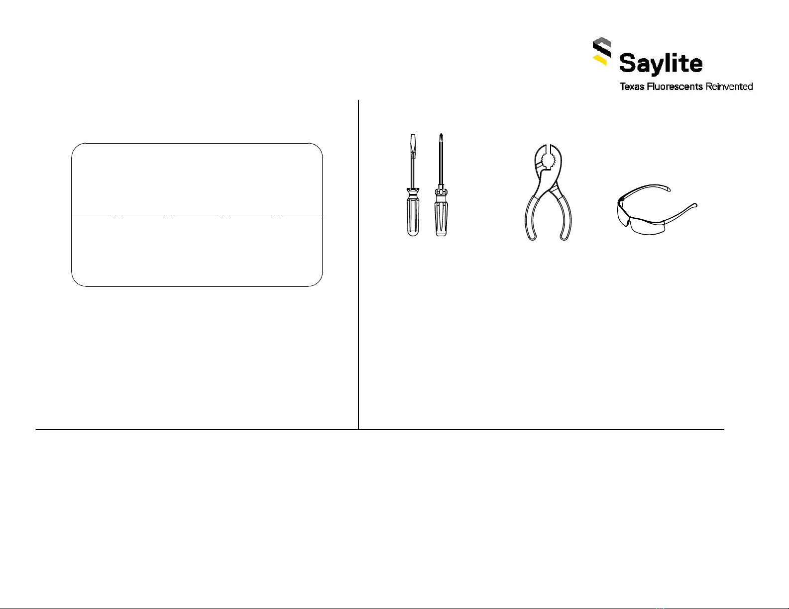
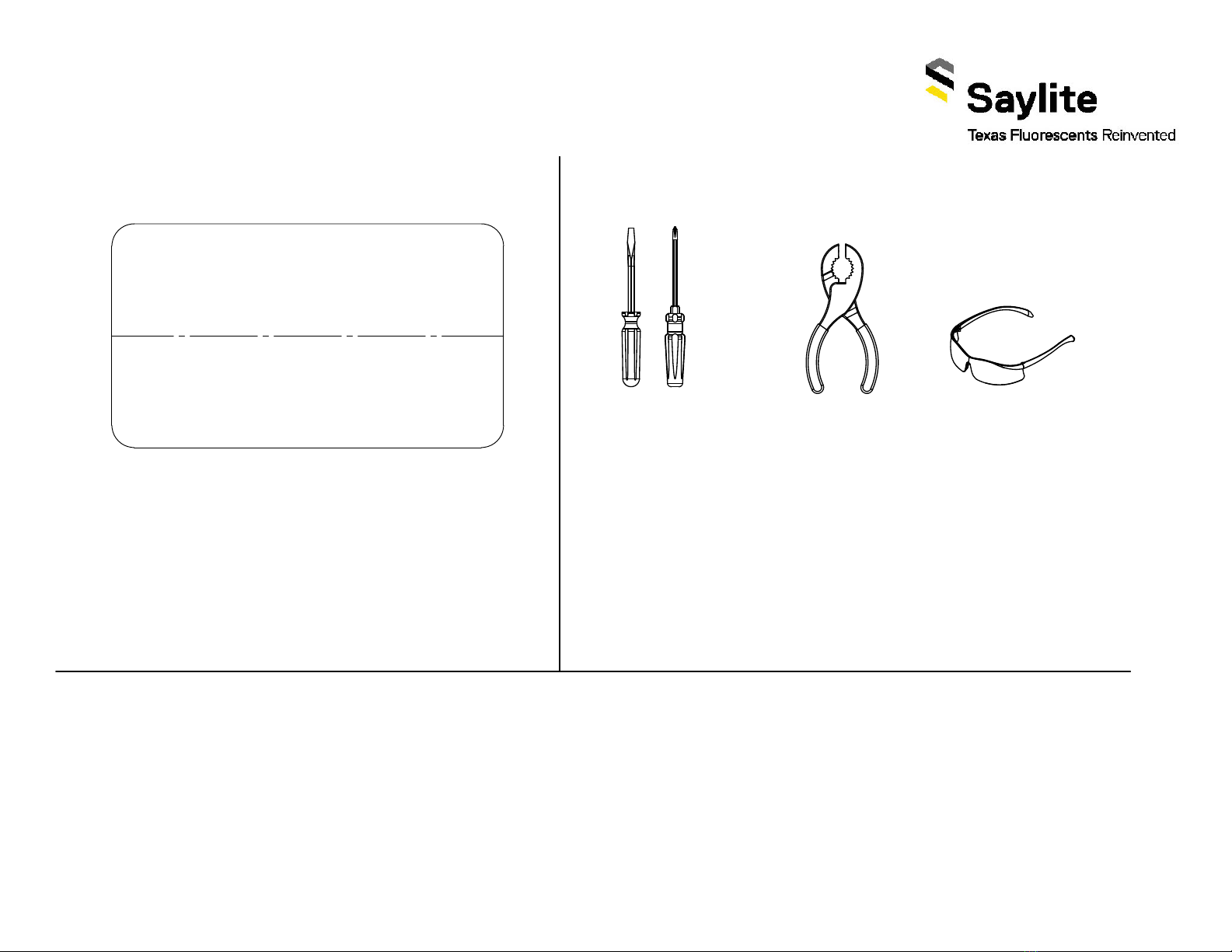
Screwdrivers
TXF-ISS-Continuous Run Installation Instructions
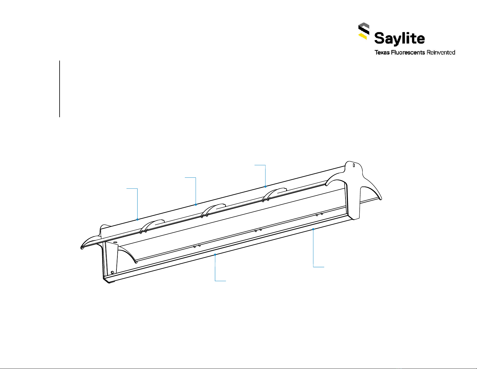
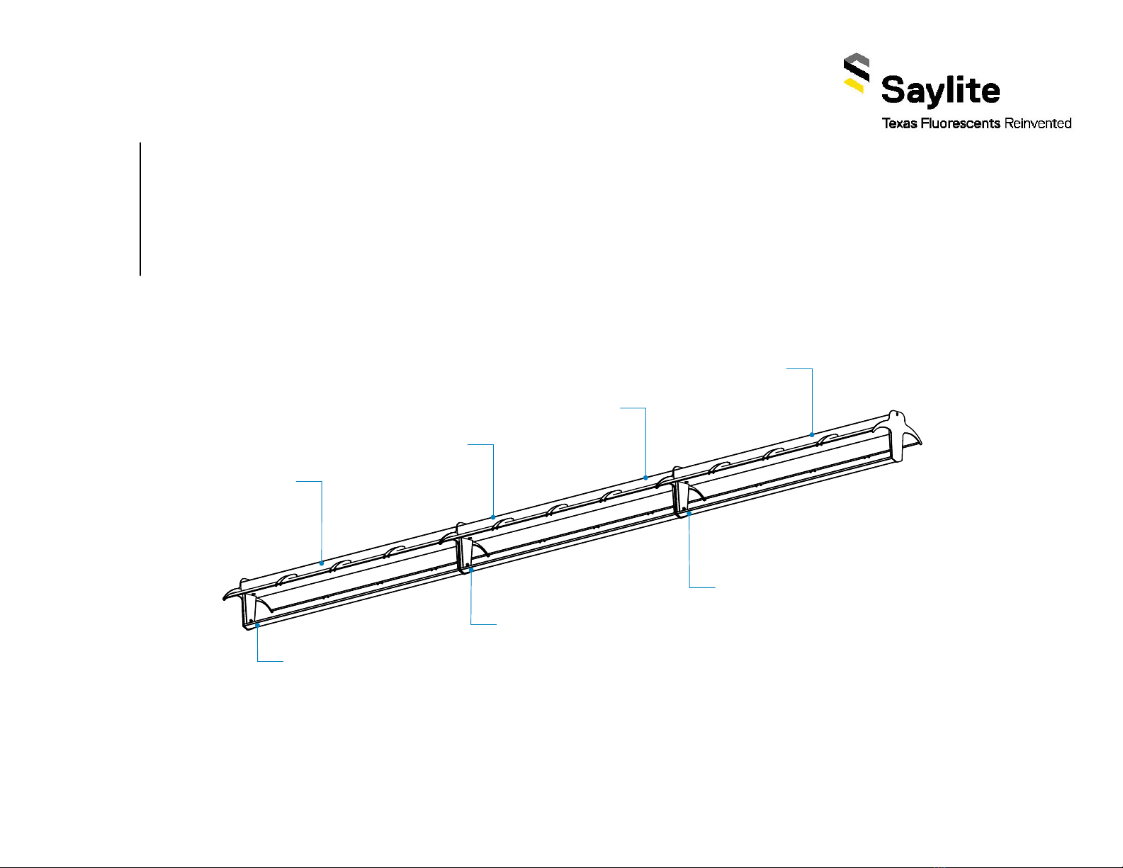
Step 2 - Identification and Preparation
A. Identify Fixtures B. Tools Neeed
FormMCM-TXF-ISS-CR,V1,05/20
Kitted Hardware
Saylite has provided the items•
listed here, with their Saylite part
numbers listed. These items can
be found in separate boxes
shipped with the fixture.
Ensure all parts are accounted•
for and set them aside until
needed.
Any additional hardware•
needed for this installation will
be provided by others.
Always use proper safety equipment when installing fixtures.•
Tools shown are recommended for standard install. Tools•
needed may vary based on actual install location conditions.
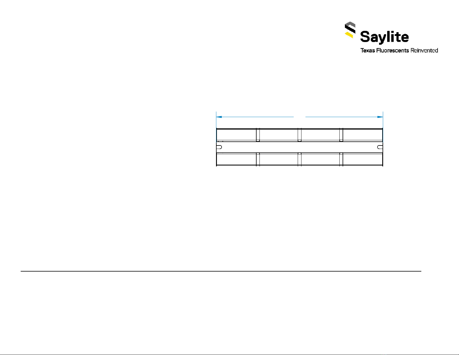
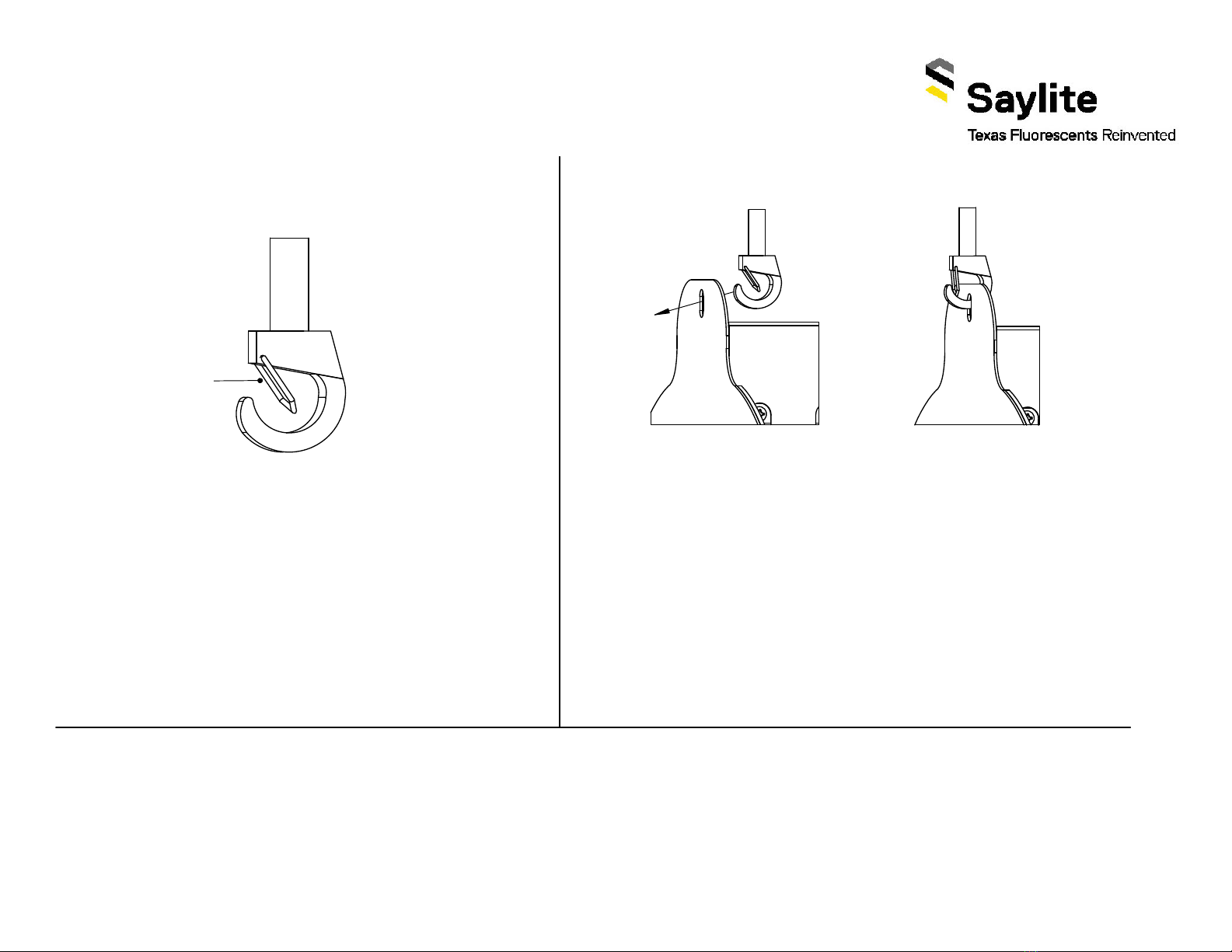
Use labels found on the box and inside the fixture bodies to•
identify bodies.
NOTE: Locations of labels can vary.•
Remove all fixtures from their boxes.•
Organize fixtures based on their labels at the install location.•
SayliteLED
Texas Fluorescents Reinvented
PART# ISSXXLQXXWXXXXLDMVXXK-B/-J/-E
PART# ISSSTXXLQXXWXXXXLDMVXXK-B/-J/-E
VOLTAGE: 120-277, 50/60HZ
WATTAGE: XX MAX
FLUX: XXXX LUMENS
CCT: XXXX
DATE CODE: XX/XX/XX
TYPE: XX
Safety GlassesPliers