manuals.online logo
Brands
  1. Home
  2. •
  3. Brands
  4. •
  5. SBG Systems
  6. •
  7. Marine Equipment
  8. •
  9. SBG Systems Navsight User manual

SBG Systems Navsight User manual

Other SBG Systems Marine Equipment manuals

SBG Systems Ellipse AHRS User manual

SBG Systems

SBG Systems Ellipse AHRS User manual

SBG Systems Navsight Solution User manual

SBG Systems

SBG Systems Navsight Solution User manual

SBG Systems Ellipse AHRS User manual

SBG Systems

SBG Systems Ellipse AHRS User manual

Popular Marine Equipment manuals by other brands

POWERWINCH 825 Operation manual

POWERWINCH

POWERWINCH 825 Operation manual

JRC JLN-628 brochure

JRC

JRC JLN-628 brochure

DIGITAL YACHT PilotLink2 Product handbook

DIGITAL YACHT

DIGITAL YACHT PilotLink2 Product handbook

Clarion CMS2 Owner's manual & installation manual

Clarion

Clarion CMS2 Owner's manual & installation manual

EBS M7000 installation manual

EBS

EBS M7000 installation manual

Kongsberg M3 Bathy installation manual

Kongsberg

Kongsberg M3 Bathy installation manual

NPK SCS-1002 operating manual

NPK

NPK SCS-1002 operating manual

Furuno FE-800 installation manual

Furuno

Furuno FE-800 installation manual

Harken 1561 instructions

Harken

Harken 1561 instructions

Simrad DD15 manual

Simrad

Simrad DD15 manual

Notifier FS-BSO Installation and maintenance instructions

Notifier

Notifier FS-BSO Installation and maintenance instructions

Raymarine ST40 Quick reference guide

Raymarine

Raymarine ST40 Quick reference guide

Raymarine Maxiview ST80 Owner's handbook

Raymarine

Raymarine Maxiview ST80 Owner's handbook

E2S E2XS112UL Instructions/service manual

E2S

E2S E2XS112UL Instructions/service manual

GUIDANCE MARINE 20- Series Installer's guide

GUIDANCE MARINE

GUIDANCE MARINE 20- Series Installer's guide

R2Sonic 2026 Operation manual

R2Sonic

R2Sonic 2026 Operation manual

COBHAM SAILOR 6000 installation manual

COBHAM

COBHAM SAILOR 6000 installation manual

Raymarine ST60 Tridata Owner's handbook

Raymarine

Raymarine ST60 Tridata Owner's handbook

manuals.online logo
manuals.online logoBrands
  • About & Mission
  • Contact us
  • Privacy Policy
  • Terms and Conditions

Copyright 2025 Manuals.Online. All Rights Reserved.

Navsight Solution
Inertial Systems for Survey Applications
Hardware Manual
Document NAVSIGHTHM 1 5
Revision 1 5 - Nov 30, 2022
Support EMEA
support@sbg-systems com
+33 1 80 88 43 70
Americas
support@sbg-systems com
+1 (657) 549-5807
Navsight Solution – Hardware Manual NAVSIGHTHM 1 5
Revision history
Rev Date Author Information
1 5 Nov 30, 2022 Mathieu Peyréga [NAVDOC-32] - Navsight rack Sync Out A pinout missing
[NAVDOC-33] - Various typo and formatting issues
[NAVDOC-34] - Fix acronyms list
[NAVDOC-35] - Update manual and hardware specs to reflect [CR-27]
[NAVDOC-36] - Fix Navsight typical automotive application sketch
[NAVDOC-37] - Change mass and power consumption
[NAVDOC-38] - Fix Subsea Apogee dimensions
[NAVDOC-39] - Add information on maximum number of pulses per second
that the HPI can receive from the Odometer
1 4 Jun 14, 2022 Alexis Guinamard [NAVDOC-23] Update transport cases accessories
[NAVDOC-21] Fixed Serial port description typos
]NAVDOC-25] Update serial port specifications (Tx/Rx)
[NAVDOC-26] Fixed Ship Motion HP latency to 150s
[NAVDOC-27] Specify RTK performance according to baseline
[NAVDOC-29] Update orientation specifications after algorithms update
[NAVDOC-30] Transferred antennas section to support center
[NAVDOC-31] Added Asterx-m3 specifications
1 3 Jul 2, 2020 Alexis Guinamard [NAVDOC-18] Update heading performance for FW 3 0
[NAVDOC-16] Updated data logger LED documentation
[NAVDOC-15] Updated PPP Correction services on NAVSIGHT-S
1 2 Sep 19, 2019 Alexis Guinamard [NAVDOC-11] Added new Trimble GNSS receiver specifications
[NAVDOC-10] Added new Apogee IMU product codes (V2)
[NAVDOC-13] Added IMU sensor specifications
[NAVDOC-12] Add virtual odometer feature
[NAVDOC-14] Updated product codes and part numbers
1 1 Feb 13, 2019 Alexis Guinamard [NAVDOC-7] Add maximum cable length specifications
[NAVDOC-6] Add CA-SPLIT-COM cable description
[NAVDOC-4] Added information about supported RTK corrections formats
[NAVDOC-1] Add Horizon IMU specifications
[NAVDOC-3] Add Rack mount processing unit specifications
[NAVDOC-8] Added electrical specifications of various modules
[NAVDOC-9] Added IMU connector specifications
1 0 Sep 28, 2018 Alexis Guinamard First ocial version
© 2007 – 2022 SBGSystems SAS All rights reserved Information in this document is subject to change
without notice Copy or redistribution of this document is forbidden without express authorization of
SBGSystems
2/73
Navsight Solution – Hardware Manual NAVSIGHTHM 1 5
Index
1 Terminology 7
2 Solution overview 8
2 1 System 9
2 2 IMU 9
2 2 1 Ekinox IMU 9
2 2 1 1 Accelerometers 9
2 2 1 2 Gyroscopes 10
2 2 1 3 Surface form factor 10
2 2 1 4 Subsea form factor 12
2 2 2 Apogee IMU 13
2 2 2 1 Accelerometers 13
2 2 2 2 Gyroscopes 13
2 2 2 3 Surface form factor 13
2 2 2 4 Subsea form factor 15
2 2 3 Horizon IMU 16
2 2 3 1 Accelerometers 16
2 2 3 2 Gyroscopes 16
2 2 3 3 Surface form factor 16
2 2 4 Specifications 17
2 3 Navsight Processing unit 18
2 3 1 Rugged packaging 18
2 3 1 1 Mechanical specifications 18
2 3 2 Rack packaging 19
2 3 2 1 Mechanical specifications 19
2 3 3 Internal GNSS (Septentrio Asterx-4, HW Revision <= 2 1) 20
2 3 4 Internal GNSS (Septentrio Asterx-m3, HW Revision >= 2 1) 21
2 3 5 Internal GNSS (Trimble, HW revision >= 1 5 and <= 2 1) 22
2 3 6 Internal GNSS (Trimble, HW revision < 1 5) 23
3 System Performance specification 24
3 1 Ekinox grade performance specifications 24
3 1 1 Common specifications 24
3 1 2 Land applications 24
3 1 3 Marine & Subsea applications 25
3 1 3 1 Heave performance 25
3 1 4 Airborne applications 25
3 2 Apogee grade specifications 26
3 2 1 Common specifications 26
3 2 2 Marine & Subsea applications 26
3 2 2 1 Heave performance 27
3 2 3 Land applications 27
3 2 4 Airborne applications 27
3 3 Horizon grade specifications 28
3 3 1 Marine applications 28
3 3 1 1 Heave performance 28
3 3 2 Land applications 29
3/73
Navsight Solution – Hardware Manual NAVSIGHTHM 1 5
3 3 3 Airborne applications 29
4 IMU interface specification 30
4 1 Surface IMU interfaces 30
4 2 Subsea IMU interfaces 30
5 Processing unit Interfaces specifications 31
5 1 Rugged version Overview 31
5 2 Rack version Overview 32
5 3 Interfacing capabilities 33
5 3 1 Supported protocols 33
5 4 Keyboard and LEDs indicators 34
5 4 1 LEDs status indicators 34
5 4 2 Buttons actions 35
5 4 2 1 Basic actions 35
5 4 2 2 Advanced actions 35
5 5 IMU interface 35
5 6 ETH interface 36
5 6 1 Accessing the Navsight web page 36
5 6 2 Connector specifications (rugged) 36
5 6 3 Connector specifications (rack) 37
5 7 CAN interface 37
5 71 Connector specifications (rugged) 38
5 7 2 Connector specifications (rack) 38
5 7 3 Electrical specifications 38
5 8 Serial ports interfaces 39
5 8 1 PORT A Interface 39
5 8 1 1 SYNC Out A functionality 39
5 8 1 2 Connector specifications (rugged) 39
5 8 1 3 Connector specifications (rack) 40
5 8 1 4 Electrical specifications 40
5 8 2 PORT B, C and D interfaces 41
5 8 2 1 Connector specifications (rugged) 41
5 8 2 2 Connector specifications (rack) 41
On the Rack version, the PORT B, C, D are accessible through a standard male DB-9 plug 41
5 8 2 3 Electrical specifications 42
5 8 3 PORT E interface 43
5 8 3 1 Connector specifications (rugged) 43
5 8 3 2 Connector specifications (rack) 44
On the Rack version, the PORT E is accessible through a standard male DB-9 plug 44
5 8 3 3 Electrical specifications 44
5 9 SYNC OUT B 45
5 9 1 1 Electrical specifications 45
5 10 SYNC In A, B, C, D and E 45
5 11 GNSS antenna connectors 46
5 11 1 Electrical specifications 46
5 11 2 GNSS antenna advice 46
5 12 Internal Datalogger 47
5 13 Power supply interface 47
5 13 1 Connector pin-out 47
4/73
Navsight Solution – Hardware Manual NAVSIGHTHM 1 5
5 13 2 Electrical specifications 48
5 14 Typical wiring recommendations 48
5 14 1 Power supply connection 48
5 14 2 Main interface connection on RS-232 49
5 14 3 CAN Bus typical wiring 49
5 14 4 GNSS connection in RS-232 mode 50
5 14 5 Duplex interfacing in RS-422 50
5 15 Typical connection topology 51
5 15 1 Navsight use in Land/Air survey applications 51
5 15 2 Navsight use in marine applications 52
6 Important notices 53
6 1 Maintenance 53
6 1 1 Subsea enclosures maintenance 53
6 2 Absolute maximum ratings 53
6 2 1 Processing units 53
6 2 2 IMU modules 53
6 3 Support 54
6 4 Warranty, liability and return procedure 54
7 Appendix A: Ordering codes and Accessories 55
71 Ekinox IMU Ordering codes 55
7 2 Apogee IMU Ordering codes 55
7 3 Horizon IMU Ordering code 55
74 Processing unit variants 56
7 5 Transport Cases 57
7 5 1 CASE-NAVS-04 57
7 6 Associated Software 57
7 6 1 Qinertia (Post-processing software) 57
7 6 2 Inertial SDK (Software Development Kit) 57
7 7 Cables 57
7 71 IMU cables 57
7 71 1 CA-NAVS-IMU-STD-#M 57
7 71 2 CA-NAVS-IMU-SUB-#M 58
7 71 3 CA-NAVS-IMU-EXT-#M 58
7 7 2 CA-PWR-24-60-CC-4M 58
7 7 3 CA-AEK-PWR-3M 59
7 74 CA-NAVS-ETH-5M 59
7 7 5 CA-NAVS-COM-2M 60
7 7 6 CA-NAVS-COM-DB-0 3M 60
7 7 7 CA-NAVS-SPLIT-COM-0 5M 61
8 Appendix B: Sub-systems mechanical outlines 62
8 1 Ekinox IMU – Surface enclosure 62
8 1 1 Top View 62
8 1 2 Right view 62
8 1 3 Front view 63
5/73
Navsight Solution – Hardware Manual NAVSIGHTHM 1 5
8 1 4 Bottom view 63
8 2 Ekinox IMU – Subsea enclosure 64
8 2 1 Top and bottom views 64
8 2 2 Front view 64
8 3 Apogee IMU – Surface enclosure 65
8 3 1 Top view 65
8 3 2 Right view 65
8 3 3 Front view 66
8 3 4 Bottom view 66
8 4 Apogee IMU – Subsea enclosure 67
8 4 1 Top and bottom views 67
8 4 2 Front view 67
8 5 Horizon IMU 68
8 5 1 Top view 68
8 5 2 Right view 68
8 5 3 Front view 69
8 5 4 Bottom view 69
8 6 Processing unit – Rugged enclosure 70
8 6 1 Top view 70
8 6 2 Right view 70
8 6 3 Front view 71
8 6 4 Back view 71
8 7 Processing unit – Rack enclosure 72
8 71 Top view 72
8 7 2 Front view 72
8 7 3 Back view 72
9 Appendix C: Products labels 73
6/73
Navsight Solution – Hardware Manual NAVSIGHTHM 1 5
1 Terminology
AHRS: Attitude and Heading Reference System
CAN (Bus): Controller Area Network
CMR: Compact Measurement Record (protocol)
DC: Direct Current
DGNSS: Dierential GNSS
DMI: Distance Measuring Instrument
DVL: Doppler Velocity Log
EKF: Extended Kalman Filter
EMI: Electro Magnetic Interferences
FIR: Finite Impulse Response (filter)
FTP: File Transfer Protocol
GND: Ground
GNSS: Global Navigation Satellite System
GPS: Global Positioning System
IMU: Inertial Measurement Unit
INS: Inertial Navigation System
IP: Internet Protocol / Ingress Protection
LNA: Low Noise Amplifier
MEMS: Micro Electro-Mechanical Systems
MRU: Motion Reference Unit
MTBF: Mean Time Between Failures
NA: Not applicable
NMEA (NMEA 0183): National Marine Electronics Association (standardized communication protocol)
PPK: Post Processing Kinematic
PPS: Pulse Per Second (signal)
RoHS: Risk Of Hazardous Substance
RMA: Return Merchandise Authorization
RMS: Root Mean Square
RTCM: Radio Technical Commission for Maritime Services (Protocol)
RTK: Real Time Kinematics
SBAS: Satellite Based Augmentation System
SDK: Software Development Kit
SP: Single Point
TBD: To Be Defined
TCP: Transmission Control Protocol
UDP: User Datagram Protocol
UTC: Coordinated Universal Time
VRE: Vibration Rectification Error
WGS84: World Geodetic System 1984
7/73
Navsight Solution – Hardware Manual NAVSIGHTHM 1 5
2 Solution overview
Navsight is a comprehensive inertial navigation solution,
specifically designed for the survey markets Leveraging
on existing SBGSystems inertial sensors, advanced
algorithms and high performance GNSS technology, it
also adds an incredibly easy to use setup
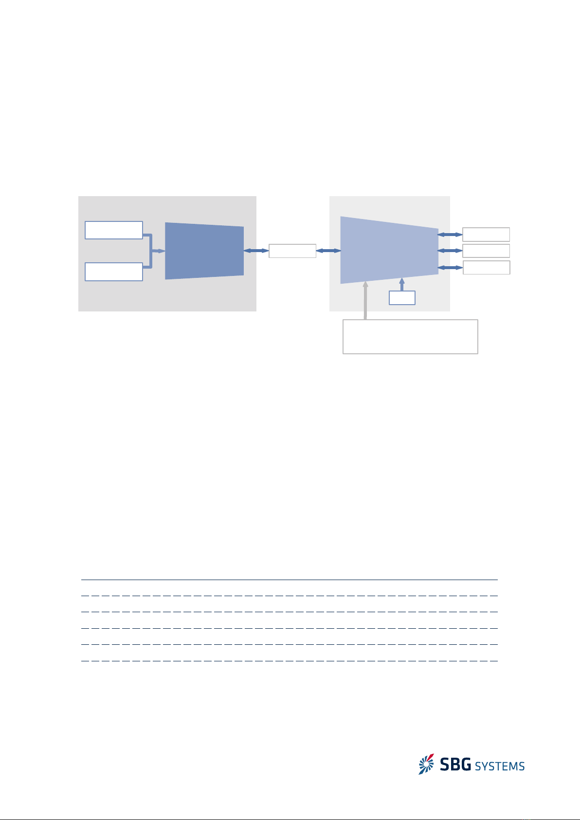
Navsight solution is composed of various components
that can be adjusted or configured according to your
specific application needs:
The IMU is the main sensing element and the most important performance driving factor In case of good
GNSS conditions and shallow water or entry level land/air survey, the Ekinox IMU can be selected In case of
more challenging conditions, such as dicult GNSS environments, or high altitude / high depth survey, the
Apogee grade is the sensor of choice to maintain the best accuracy In case of airborne survey with single
antenna setup, or more generally, for ultimate accuracy, the Horizon IMU should be selected All IMUs are
delivered in a rugged IP-68 package, and Ekinox / Apogee IMUs have optional salt water proof titanium
enclosures
The other main component is the processing unit Available in a rugged IP-67 form factor or easy to
integrate rack enclosure, it embeds all the navigation algorithms processing, a dual antenna, triple
frequency GNSS receiver (optional), capable of PPP and centimetre precision using RTK, and all inputs and
outputs interfaces In addition to the standard Inertial Navigation System outputs (precise position, velocity
and attitude), the marine variant of Navsight Processing unit also delivers precise heave and delayed heave
For some cost sensitive applications, it is also possible to select a simple MRU setup, with only roll, pitch,
yaw and heave outputs
For easier installation, the Navsight processing unit and IMU can be installed at dierent locations: IMU
close to the location we want to track (eg multibeam sonar), and processing unit, close to user
SBGSystems tested successfully installations with more than 50m distance between processing unit and
IMU
The Navsight processing unit can be connected to a wide range of aiding sensors such as GNSS, DVL,
Odometer
To achieve the best performance in every project, specific error models have been implemented to meet
applications requirements and to adapt the solution to your vehicle Sensor configuration is made easy
through the modern embedded web interface
Finally, the 8 GB embedded data-logger enables seamless post processing work-flow with Qinertia
software This makes Navsight solution suitable for the most demanding applications
Navsight solution is fully compatible with integrated Ekinox and Apogee series in terms of protocols,
firmware and features
8/73
Figure 2.1: The Navsight Rugged processing unit
Navsight Solution – Hardware Manual NAVSIGHTHM 1 5
2 1 System
The following diagram shows the basic organization of the Navsight solution Internal GNSS receiver is
optional
The RS-485 link between IMU and processing unit allows secure and long distance communication
(e g 50m)
2 2 IMU
The IMU is the main component that will drive the overall system performance Several IMU configurations
are proposed to address dierent applications requirements
2.2.1. Ekinox IMU
Ekinox IMU has been designed to deliver an exceptional performance in a very compact and cost eective
package Ekinox IMU integrates low noise gyroscopes The integrated accelerometers are ultra low noise and
highly ecient in vibrating environments due to a low Vibration Rectification Error Sensor specifications
are listed below
2 2 1 1 Accelerometers
A2 A3 Remarks
Full scale (g)± 8 ± 14
Velocity Random Walk (µg/√hz) 7 40 Allan variance – @ 25°C
In run bias instability (µg)2 10 Allan variance – @ 25°C
Vibration Rectification Error (µg/g²) <200 <50 VRE – 20Hz – 2kHz
Bandwidth (Hz) 433 433 Attenuation of 3dB
Orthogonality (°) < 0 02 < 0 02 Over temperature range
9/73
Figure 2.2: Navsight simp ified b ock diagram
Sensors sampling &
Calibration
Coning & Sculling
integrals @ 1 kHz
EKF and output
@ 200 Hz
IMU Processing Unit
3 Axis
Gyroscopes
3 Axis
Accelerometers
CAN
RS-232/422
GNSS*
Aiding Equipment
» Dual Antenna GPS, GPS/GNSS, RTK
» Odometer, DVL
ETHERNET
RS-485
Navsight Solution – Hardware Manual NAVSIGHTHM 1 5
2 2 1 2 Gyroscopes
G4 Remarks
Full scale (°/s) ± 300
In run bias instability (°/hr) 0 5 Allan variance – @ 25°C
Angular Random Walk (°/√hr) 0 14 Allan variance – @ 25°C
Bandwidth (Hz) 60 Attenuation of 3dB
Orthogonality (°) < 0 02 Over temperature range
2 2 1 3 Surface form factor
The Ekinox enclosure is composed of two anodized aluminum
parts (6061), one for the cover and one for the base plate The
device uses high quality alloys and connectors to oer a full IP-68
enclosure and a good resistance to harsh environments
The Ekinox IMU connector is a high quality push pull connector
that oers IP-68 protection even unconnected
Warning: The Ekinox IMU surface model is not designed
for prolonged operation in salt water environments
Check section Maintenance for more details about
operation in sea water environments
The table below summarizes all mechanical and environmental specifications
Electrical and Mechanical Specifications
Enclosure materials Anodized Aluminum (6061)
Dimensions 5 8 x 10 0 x 8 6 cm
Weight 426g
Input power voltage 12 – 36V DC – isolated power supply
Power consumption 1 6W typical
Environmental specifications
IP rating IP-68 (24 hours at 1 meters)
Humidity Sealed, no limit
Operating Temperature
range
-20°C to 60°C – specified range
-40°C to 71°C – operating range
Storage Temperature range -40°C to 85°C
Shocks 500g for 0 3ms
Operating Vibrations 3g RMS – 20Hz to 2kHz as per MIL-STD-810G (A2 range options)
8g RMS – 20Hz to 2kHz as per MIL-STD-810G (A3 range options)
MTBF 50000 hours
Calibration interval None required, maintenance free
10/73
Figure 2.3: Ekinox Surface IMU