SBG Systems Ellipse AHRS User manual

Ellipse AHRS & INS
High Performance, Miniature Inertial Sensors
Hardware Manual
intro
Document E IPSEHM.1.2
Revision 1.2 - Mar 6, 2017
Support [email protected]om
+33 1 80 88 45 00
SBG Systems
3bis, chemin de la Jonchère
92500 Rueil-Malmaison
FRANCE

Ellipse AHRS & INS – Hardware Manual E IPSEHM.1.2
Revision history
Rev. Date Author Information
1.2 Mar 6, 2017 Alexis Guinamard [E IDOC-39] Split the User manual into hardware manual and other common
documentations (firmware manual and Technical Reference Manual)
[E IDOC-38] Document the automatic 1Hz GGA output on PORT-C for E IPSE-D when
RTCM corrections are enabled
[E IDOC-40] Detail interfaces and ports capabilities depending on Ellipse model
[E IDOC-36] Update support contact details
[E IDOC-32] Updated RS-232/RS-422 electrical specifications
[E IDOC-41] Updated warranty period (2 years)
[E IDOC-42] Clarified automotive dead reckoning performance
[E IDOC-44] Added SP IT cables description
1.1 May 5, 2015 Alexis Guinamard [E IDOC-4] Added WMM2015 and WGS84 gravity model information
[E IDOC-5] Added E IPSE D information (specification, accessories, ...)
[E IDOC-6] Added support for Novatel protocol (GPS aiding)
[E IDOC-8] Added comments about vibration resistance validity
[E IDOC-9] Added pressure sensor specification
[E IDOC-12] Fixed Gyro angular random walk unit
[E IDOC-13] Fixed IP-68 definition
[E IDOC-14] Fixed Missing Sync Out Description
[E IDOC-16] Added official support for additional output interfaces PORT C and PORT E
[E IDOC-21] Added accessories weights when available
1 Oct 7, 2014 Alexis Guinamard First public version
PRE2 Aug 25, 2014 Alexis Guinamard Second pre-version of this document
PRE1 Mar 6, 2014 Alexis Guinamard First pre-version of this document
© 2007 – 2017, SBG Systems SAS. All rights reserved. Information in this document is subject to change
without notice. Copy or redistribution of this document is forbidden without express authorization of SBG
Systems.
2/47

Ellipse AHRS & INS – Hardware Manual E IPSEHM.1.2
Index
Terminology...........................................................................................................................................6
1. Introduction........................................................................................................................................ 7
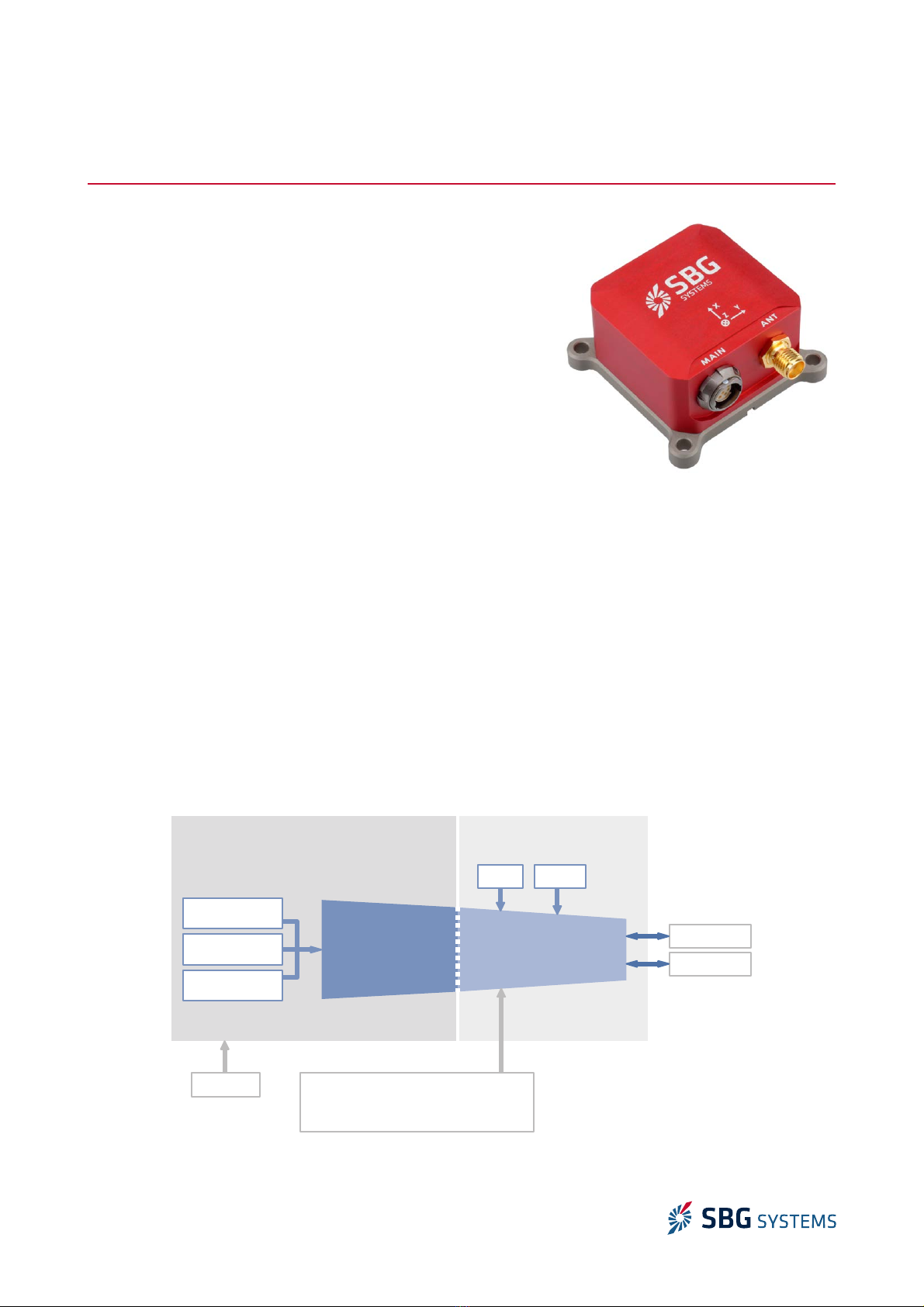
1.1. Ellipse Overview........................................................................................................................................... 7
1.2. Inertial measurement unit......................................................................................................................... 8
1.2.1. Accelerometers......................................................................................................................................................................... 8
1.2.2. Gyroscopes................................................................................................................................................................................ 9
1.3. Aiding sensors........................................................................................................................................... 10
1.3.1. Internal Magnetometers......................................................................................................................................................... 10
1.3.2. Ellipse-N internal GNSS receiver............................................................................................................................................. 11
1.3.3. Ellipse-D internal GNSS receiver............................................................................................................................................. 11
1.3.4. Internal barometric altimeter................................................................................................................................................. 12
1.3.5. External sensors...................................................................................................................................................................... 12
1.3.5.1. Third party GNSS receiver.............................................................................................................................................. 12
1.3.5.2. Odometer....................................................................................................................................................................... 12
1.4. System Performance................................................................................................................................. 13
1.4.1. Ellipse-A orientation performance.......................................................................................................................................... 13
1.4.1.1. Orientation specifications............................................................................................................................................... 13
1.4.2. Ellipse-E/ N orientation and navigation performance.......................................................................................................... 13
1.4.2.1. and applications............................................................................................................................................................ 13
1.4.2.2. Marine & Subsea applications....................................................................................................................................... 13
1.4.2.3. Airborne applications.................................................................................................................................................... 14
1.4.3. Ellipse-D orientation and navigation performance............................................................................................................... 14
1.4.3.1. and applications........................................................................................................................................................... 14
1.4.3.2. Marine & Subsea applications....................................................................................................................................... 15
1.4.3.3. Airborne applications..................................................................................................................................................... 15
1.4.4. Heave performance................................................................................................................................................................. 15
2. Mechanical and Electrical specifications...........................................................................................16
2.1. Mechanical specifications......................................................................................................................... 16
2.1.1. Overview................................................................................................................................................................................... 16
2.1.2. Specifications.......................................................................................................................................................................... 16
2.1.3. Device mechanical alignment................................................................................................................................................. 17
2.1.4. Origin of measurements......................................................................................................................................................... 17
2.1.5. Device labels............................................................................................................................................................................ 17
2.1.6. Ellipse-A mechanical outline.................................................................................................................................................. 18
2.1.6.1. Front view....................................................................................................................................................................... 18
2.1.6.2. Top view......................................................................................................................................................................... 18
2.1.6.3. Right view...................................................................................................................................................................... 19
2.1.6.4. Bottom view................................................................................................................................................................... 19
2.1.7. Ellipse-E mechanical outline................................................................................................................................................... 20
2.1.7.1. Front view....................................................................................................................................................................... 20
2.1.7.2. Top view......................................................................................................................................................................... 20
2.1.7.3. Right view....................................................................................................................................................................... 21
2.1.7.4. Bottom view................................................................................................................................................................... 21
2.1.8. Ellipse-N mechanical outline................................................................................................................................................. 22
2.1.8.1. Front view...................................................................................................................................................................... 22
2.1.8.2. Top view......................................................................................................................................................................... 22
2.1.8.3. Right view..................................................................................................................................................................... 23
2.1.8.4. Bottom view.................................................................................................................................................................. 23
3/47

Ellipse AHRS & INS – Hardware Manual E IPSEHM.1.2
2.1.9. Ellipse-D mechanical outline.................................................................................................................................................. 24
2.1.9.1. Front view....................................................................................................................................................................... 24
2.1.9.2. Top view......................................................................................................................................................................... 24
2.1.9.3. Right view...................................................................................................................................................................... 25
2.1.9.4. Bottom view.................................................................................................................................................................. 25
2.2. Electrical specifications........................................................................................................................... 26
2.2.1. Ellipse-A without GPS aiding................................................................................................................................................. 26
2.2.2. Ellipse-E with external aiding only........................................................................................................................................ 26
2.2.3. Ellipse-N with embedded GNSS............................................................................................................................................ 26
2.2.4. Ellipse-D with embedded dual antenna GNSS..................................................................................................................... 27
2.2.5. Main connector....................................................................................................................................................................... 27
2.2.5.1. Connector specifications............................................................................................................................................... 27
2.2.5.2. Connector pin out for Ellipse B1 versions.................................................................................................................... 28
2.2.5.3. Connector pin out for Ellipse B2 versions.................................................................................................................... 28
2.2.6. Auxiliary connector (Ellipse-E).............................................................................................................................................. 28
2.2.6.1. Connector specifications.............................................................................................................................................. 28
2.2.6.2. Connector pin out......................................................................................................................................................... 29
2.2.7. Auxiliary connector (Ellipse-D)............................................................................................................................................... 29
2.2.7.1. Connector specifications............................................................................................................................................... 29
2.2.7.2. Connector pin out.......................................................................................................................................................... 29
2.2.8. Electrical specifications......................................................................................................................................................... 30
2.2.8.1. Electrical specifications................................................................................................................................................ 30
2.2.9. GPS antenna connector (Ellipse-N and D)............................................................................................................................. 31
2.2.9.1. GPS antenna advice for Ellipse-N.................................................................................................................................. 31
2.2.9.2. GPS antenna advice for Ellipse-D................................................................................................................................ 32
3. Interfaces specifications..................................................................................................................33
3.1. Overview.................................................................................................................................................... 33
3.1.1. Interfaces availability and multiplexing................................................................................................................................. 33
3.2. Serial interfaces....................................................................................................................................... 34
3.2.1. Supported protocols............................................................................................................................................................... 34
3.2.2. Ports functions Mapping....................................................................................................................................................... 34
3.2.2.1. Ellipse A version............................................................................................................................................................ 34
3.2.2.2. Ellipse E version............................................................................................................................................................ 35
3.2.2.3. Ellipse N........................................................................................................................................................................ 35
3.2.2.4. Ellipse D version............................................................................................................................................................ 35
3.3. CAN 2.0 A/B interface............................................................................................................................. 36
4. Important notices............................................................................................................................37
4.1. Absolute maximum ratings...................................................................................................................... 37
4.2. Maintenance............................................................................................................................................. 37
4.2.1. Cleaning................................................................................................................................................................................... 37
4.3. Support.................................................................................................................................................... 38
4.4. Warranty, liability and return procedure................................................................................................. 38
5. Appendix A: Ordering codes and Accessories...................................................................................39
5.1. Ellipse ordering codes............................................................................................................................... 39
5.2. Development kits..................................................................................................................................... 39
5.2.1. DK-E I-[B, ]........................................................................................................................................................................... 39
5.2.2. DK-E I-D................................................................................................................................................................................ 40
4/47

Ellipse AHRS & INS – Hardware Manual E IPSEHM.1.2
5.3. Cables....................................................................................................................................................... 40
5.3.1. CA-E I-USB-3M...................................................................................................................................................................... 40
5.3.2. CA-E I-D-USB-3M................................................................................................................................................................. 40
5.3.3. CA-PSU-12V-1.5M.................................................................................................................................................................. 40
5.3.4. CA-E I-RS232-CAN-3M.......................................................................................................................................................... 41
5.3.5. CA-E I-RS422-3M................................................................................................................................................................. 42
5.3.6. CA-E I-SP IT-RS232-DB-0.5M............................................................................................................................................. 43
5.3.7. CA-E I-SP IT-CAN-DB-0.5M.................................................................................................................................................. 43
5.3.8. CA-E I-SP IT-RS232-DB-0.5M............................................................................................................................................. 44
5.4. GNSS antennas........................................................................................................................................ 45
5.4.1. ANT-TA -TW-32-2410-00-3000 and ANT-TA -TW-32-2710-00-3000................................................................................... 45
5.4.1.1. Performance specifications........................................................................................................................................... 45
5.4.1.2. Mechanical drawing...................................................................................................................................................... 45
5.4.2. ANT-ACM-G5ANT-1A196MNS-1............................................................................................................................................. 46
5.4.2.1. Performance specifications.......................................................................................................................................... 46
5.4.2.2. Mechanical drawing..................................................................................................................................................... 46
5.4.3. High performance GNSS antennas....................................................................................................................................... 47
5.4.3.1. TNC Cables..................................................................................................................................................................... 47
5/47

Ellipse AHRS & INS – Hardware Manual E IPSEHM.1.2
Terminology
ADC: Analog to Digital Converter
AHRS: Attitude and Heading Reference System
CAN (Bus): Controller Area Network
DHCP: Dynamic Host Configuration Protocol
DV : Doppler Velocity og
EKF: Extended Kalman Filter
EEPROM: Electrically-Erasable Programmable Read-Only Memory
FIR: Finite Impulse Response (filter)
FTP: File Transfer Protocol
FS: Full Scale
FOG: Fiber Optic Gyroscope
GNSS: Global Navigation Satellite System
GPS: Global Positioning System
IIR: Infinite Impulse Response (filter)
IMU: Inertial Measurement Unit
INS: Inertial Navigation System
IP: Internet Protocol
B : ong Baseline
MAC (address): Media Access Control
MEMS: Micro Electro-Mechanical Systems
NED: North East Down (coordinate frame)
NA: Not applicable
NMEA (NMEA 0183): National Marine Electronics Association (standardized communication protocol)
PPS: Pulse Per Second (signal)
RAM: Random Access Memory
RMA: Return Merchandize Authorization
RMS: Root Mean Square
RTCM: Radio Technical Commission for Maritime Services (Protocol)
RTK: Real Time Kinematics
SI: International System of Units
TBD: To Be Defined
TCP: Transmission Control Protocol
UDP: User Datagram Protocol
UTC: Coordinated Universal Time
USB : Ultra Short Base ine
VRE: Vibration Rectification Error
WGS84: World Geodetic System 1984
WMM: World Magnetic Model
6/47

Ellipse AHRS & INS – Hardware Manual E IPSEHM.1.2
1. Introduction
Ellipse series is a line of miniature, high-performance MEMS based
Inertial Systems which achieve exceptional orientation and
navigation performance in a miniature and affordable package. It
includes an Inertial Measurement Unit (IMU) and runs an on-board
enhanced Extended Kalman Filter (EKF). The Ellipse line is divided
in a comprehensive set of sensors:
●The Ellipse-A version is an attitude and Heading Reference
System (AHRS), providing accurate orientation in dynamic
conditions.
●The Ellipse-E, N and D models are Inertial Navigation
Systems (INS), providing both orientation and navigation
data. The use of GNSS data or other aiding equipment such
as odometer or internal barometric sensor can be used to
provide accurate navigation data, but also to improve
orientation accuracy:
●The Ellipse-E model can be connected to an external GNSS receiver.
●The Ellipse-N model embeds an industrial GNSS receiver in a miniature package.
●The Ellipse-D embeds a survey grade GNSS receiver with dual antenna heading for excellent
heading performance in magnetic denied environments. Targeting demanding application, it is
also capable of post-processing, thanks to the internal GNSS raw data output.
To achieve the best performance in every project, specific error models have been implemented to meet
applications requirements. Sensor configuration is made easy through the sbgCenter interface, provided in
the SDK. The Ellipse supports a proprietary protocol for best performance, but also standard protocols such
as NMEA for direct integration into existing applications.
1.1. Ellipse Overview
The following diagram shows the basic organization of an Ellipse-E or N. On the Ellipse-A version, this block
diagram is slightly simplify as there is no GPS, barometer inside.
7/47
Figure 1.1: The Ellipse INS (N model)
Figure 1.2: Ellipse simplified block diagram
Sensors sampling &
Calibration
Coning & Sculling
integrals @ 1 kHz
EKF and output
@ 200 Hz
IMU DATA FUSION
3 Axis
Gyroscopes
3 Axis
Accelerometers
3 Axis
Magnetometers
POWER
CAN
SERIA
GPS
Aiding Equipments
» Dual Antenna GPS, GPS/GNSS, RTK
»
Odometer
BARO

Ellipse AHRS & INS – Hardware Manual E IPSEHM.1.2
1.2. Inertial measurement unit
As an IMU is the main component of an inertial navigation system, the Ellipse IMU has been carefully
designed to take full advantage and performance of MEMS technology.
1.2.1. Accelerometers
The Ellipse IMU embeds a set of 3 MEMS capacitive accelerometers. Coupled with advanced filtering
techniques and sculling integrals, these accelerometers will provide consistent performance, even in
vibrating environment.
A2 A3 Remarks
Full scale (
g
)8 16
Scale factor stability (%) 0.1 0.1
Non- inearity (% of FS) 0.2 0.2
One year bias stability (m
g
)5 10
Velocity Random Walk (µ
g
/√hz) 100 (X, Y)
150 (Z)
200 (X, Y)
300 (Z)
Allan variance – @ 25°C
In run bias instability (µ
g
)20 40 Allan variance – @ 25°C
Vibration Rectification Error (m
g
/
g
²) 7 4
Bandwidth (Hz) 250 250 Internal low pass filters attenuation < 3 dB
Sampling rate (kHz) 3 3
Orthogonality (°) < 0.05 < 0.05
8/47

Ellipse AHRS & INS – Hardware Manual E IPSEHM.1.2
1.2.2. Gyroscopes
The set of 3 high end industrial grade MEMS gyroscopes is sampled at 10 KHz. An efficient FIR filter and
coning integrals computations ensures best performance in vibrating environments.
G2 G3 G4 G5 Remarks
Full scale (°/s) 100 200 450 1000
Scale factor stability (%) 0.05 0.05 0.05 0.05
Non- inearity (% of FS) 0.05 0.05 0.05 0.05
One year bias stability (°/s) 0.2 0.2 0.2 0.4 Total composite bias
In run bias instability (°/hr) 8 8 8 10 Allan variance – @ 25°C
Angular Random Walk (°/√hr) 0.16 0.16 0.18 0.18 Allan variance – @ 25°C
Bandwidth (Hz) 133 133 133 133 Internal Gyro bandwidth
Sampling rate (kHz) 10 10 10 10 Advanced anti-aliasing FIR filter
Orthogonality (°) 0.05 0.05 0.05 0.05
9/47

Ellipse AHRS & INS – Hardware Manual E IPSEHM.1.2
1.3. Aiding sensors
Many different aiding sensors can be used to aid the Ellipse INS.
1.3.1. Internal Magnetometers
A set of three Anisotropic Magneto-resistive magnetometers is embedded within the Ellipse. This
technology provides a very high sensitivity compared to coil based technologies.
Although part of the Ellipse internal IMU, the magnetometer is in fact considered as an “aiding sensor” and
is not mandatory for proper operation.
Nevertheless, in many applications such AHRS applications, airborne or several marine applications, this
magnetometer is still a reliable and efficient way to observe heading.
Note: Magnetometer use requires a specific in place calibration in order to compensate surrounding
ferromagnetic materials and magnets. Please refer to the Ellipse Hard and Soft Iron Calibration
Manual for more information about this.
Warning: Note that magnetometer sampling design makes it impossible to reject signal
frequencies above 180Hz. User should ensure that high frequency noise is not disturbing
magnetometers at the sensor's location.
Specifications Remarks
Full scale (Gauss) 8
Scale factor stability (%) 0.5
inearity (% of FS) 0.1
Noise (µGauss) 200 Over 1 to 25 Hz band
Bias stability (m Gauss) 0.5
Bandwidth (Hz) 110
Resolution (mGauss) 2
Sampling rate (Hz) 220
Orthogonality (°) 0.1 After user magnetic calibration
10/47

Ellipse AHRS & INS – Hardware Manual E IPSEHM.1.2
1.3.2. Ellipse-N internal GNSS receiver
The Ellipse-N embeds an industrial GNSS receiver ( 1 GPS + G ONASS or GPS + BEIDOU), capable of DGPS
positioning using either SBAS or third party base station. With a refresh rate of 5Hz, this receiver has an
excellent sensitivity for continuous tracking under challenging environments.
Specification Remark
Channels 72
Signal tracking GPS 1 C/A
G ONASS 10F
QZSS 1 C/A
BeiDou B1
SBAS 1 C/A: WAAS, EGNOS, MSAS
Horizontal position accuracy 2.0 m CEP GPS + G ONASS + SBAS or DGPS
Velocity accuracy 0.1 m/s RMS
Sensitivity Tracking & Navigation;
Cold start:
-167dBm
-148dBm
Time to First Fix Cold start < 26 s
Hot start < 1.5s
Output frequency 5 Hz
Diff. corrections RTCM 2.3 Sent via PORT D
Operational limits Dynamics: < 4
g
Velocity: 500 m/s
Altitude: 50 000 m
1.3.3. Ellipse-D internal GNSS receiver
The Ellipse-D embeds a survey grade GNSS receiver ( 1/ 2 GPS, G ONASS, BEIDOU, GA I EO), capable of
DGPS positioning using either SBAS or third party base station. With a refresh rate of 5Hz, this receiver
provides best accuracy and reliability in harsh GNSS environments.
Specification Remark
Channels 120
Signal tracking GPS: 1, 2, 2C
G ONASS: 1, 2
Galileo: E1, E5b
Beidou B1, B2,
SBAS, QZSS
GPS 1/ 2, SBAS, QZSS in standard.
Other signals available in option
Horizontal position accuracy Single point 1 1.5 m RTK precision available in option
Single point 1/ 2 1.2 m
SBAS / DGPS 0.6 m / 0.4 m
RTK 1 cm + 1ppm
Velocity accuracy 0.03 m/s RMS
True Heading Accuracy 0.2°
0.1°
1m baseline
2m baseline
Baseline should not exceed 3m
Velocity limit 515 m/s Due to export licenses
Time to First Fix Cold start < 50 s
Hot start < 35s
Signal reacquisition 1 < 0.5 s
2 < 1.0 s
11/47

Ellipse AHRS & INS – Hardware Manual E IPSEHM.1.2
Specification Remark
Output frequency 5 Hz
Diff. Corrections RTCA, RTCAOBS2
RTCM V2.3, V3
CMR, CMR+
Sent via serial PORT D
Options BEIDOU, G ONASS, RTK
1.3.4. Internal barometric altimeter
The Ellipse-N, E and D models embed a MEMS pressure sensor, used as altimeter. This pressure sensor is
fully calibrated and temperature compensated making it ideal to measure accurately absolute pressure.
The Ellipse converts this absolute pressure into altitude using the Standard Atmosphere model, assuming a
constant temperature gradient over altitude, and a sea pressure level of 1013,25 hPa.
Barometer specifications
Pressure sensor Specification Remarks - Conditions
Resolution 1.2 Pa 10 cm resolution
Pressure accuracy
± 50 Pa
± 200 Pa
± 350 Pa
Relative – [25°C], 700...1100 hPa
Absolute – [0...50°C], 450...1100 hPa
Absolute – [-20...85°C], 450...1100 hPa
ong term stability < 100 Pa/yr
Update Rate 100 Hz
1.3.5. External sensors
1.3.5.1. Third party GNSS receiver
The Ellipse-E model does not include a GNSS receiver, but can be connected to an external GNSS module. All
GNSS receivers will provide velocity and position aiding. In some applications such as automotive ones, the
GPS course can also be used as heading reference input.
Dual antenna systems can also provide a True Heading aiding. RTK GPS receivers can be used to improve
positioning accuracy.
1.3.5.2. Odometer
In addition to the GNSS aiding, the Ellipse-N and E versions includes an odometer input which can greatly
improve performance in challenging environments such as urban canyons. The odometer provides a reliable
velocity information even during GPS outages. This increases significantly the dead reckoning accuracy.
The Ellipse handles quadrature output or compatible odometers in order to support forward and backward
directions.
Note: Odometer integration is made really simple as the Kalman filter will finely adjust odometer's
gain and will correct residual errors in the odometer alignment and lever arm.
12/47

Ellipse AHRS & INS – Hardware Manual E IPSEHM.1.2
1.4. System Performance
All specifications are rated to 1 , over -40°C to +85°C (-40 to σ185°F) unless otherwise stated.
These specifications have been measured based on typical mission scenarios with simulated GPS outages
and compared to post processed RTK data of a high end FOG based INS.
1.4.1. Ellipse-A orientation performance
1.4.1.1. Orientation specifications
Performance Remarks
Measurement range 360° in all axes, no mounting limitation
Roll / Pitch accuracy < 0.2° Medium dynamic conditions – No long term accelerations
Yaw Accuracy 0.8° Clean magnetic environment – Magnetic calibration performed
1.4.2. Ellipse-E/ N orientation and navigation performance
For each application, the accuracy parameters are defined in different positioning modes, explained below:
●SP refers to Single Point mode and is the default 1 GPS / G ONASS fix quality
●RTK stands for Real Time Kinematics with a typical 1 cm accuracy position
●Odometer Aiding is specified when an odometer provides velocity (automotive applications)
1.4.2.1. and applications
All specifications are valid with DMI (odometer) aiding for typical land applications trajectories.
Outage
Duration
Positioning
Mode
Position Accuracy Velocity Accuracy Attitude Accuracy (°)
Horizontal Vertical Horizontal Vertical Roll / Pitch Heading
No Outage SP 2 m 2.5 m 0.1 m/s 0.1 m/s 0.2 ° 0.3 °
RTK 0.02 m 0.04 m 0.05 m/s 0.05 m/s 0.2 ° 0.3 °
10 s SP 2.5 m 3 m 0.1 m/s 0.1 m/s 0.2 ° 0,3 °
RTK 0.7 m 0.6 m 0.1 m/s 0.1 m/s 0.2 ° 0.3 °
60 s / 1km SP 9 m 6 m 0.1 m/s 0.1 m/s 0.2 ° 0.5 °
RTK 7 m 4 m 0.1 m/s 0.1 m/s 0.2 ° 0.5 °
1.4.2.2. Marine & Subsea applications
Outage
Duration
Positioning
Mode
Position Accuracy Velocity Accuracy Attitude Accuracy (°)
Horizontal Vertical Horizontal Vertical Roll / Pitch Heading
No outage
SP 2 m 2.5 m 0.1 m/s 0.1 m/s 0.2 ° 0.8 °
RTK / Dual
antenna GPS 0.02 m 0.04 m 0.05 m/s 0.05 m/s 0.2 ° 0.2 °
10 s
SP 3 m 3.5 m 0.2 m/s 0.2 m/s 0.3 ° 0.8 °
RTK / Dual
antenna GPS 1 m 1 m 0.15 m/s 0.15 m/s 0.3 ° 0.3 °
Note: In case of standalone dual antenna GNSS system use, heading accuracy parameters listed in
“RTK / Dual antenna GPS” lines may apply.
13/47

Ellipse AHRS & INS – Hardware Manual E IPSEHM.1.2
1.4.2.3. Airborne applications
Positioning Mode Position Accuracy Velocity Accuracy Attitude Accuracy (°)
Horizontal Vertical Horizontal Vertical Roll / Pitch Heading
SP 2 m 2.5 m 0.1 m/s 0.1 m/s 0.2 ° 0.5 °
RTK 0.02 m 0.04 m 0.05 m/s 0.05 m/s 0.1 ° 0.4 °
1.4.3. Ellipse-D orientation and navigation performance
For each application, the accuracy parameters are defined in different positioning modes, explained below:
●SP refers to Single Point mode and is the default 1/ 2 GPS fix quality
●RTK stands for Real Time Kinematics with a typical 1 cm accuracy position
●Odometer Aiding is specified when an odometer provides velocity (automotive applications)
●DV aided refers to Doppler velocity og sensor, providing velocity information (bottom tracking)
●PPK refers to the Post-processing Kinematic solution
1.4.3.1. and applications
All specifications are valid with DMI (odometer) aiding for typical land applications trajectories.
Outage
Duration Positioning Mode Position Accuracy Velocity Accuracy Attitude Accuracy (°)
Horizontal Vertical Horizontal Vertical Roll / Pitch Heading
No outage
SP 1.2 m 1.5 m 0.03 m/s 0.03 m/s 0.1 ° 0.2 °
RTK 0.02 m 0.04 m 0.03 m/s 0.03 m/s 0.1 ° 0.2 °
PPK 0.01 m 0.02 m 0.02 m/s 0.02 m/s 0.05 ° 0.1 °
10 s
SP 1.7 m 2 m 0.1 m/s 0.1 m/s 0.1 ° 0.2 °
RTK 0.5m 0.4 m 0.1 m/s 0.1 m/s 0.1 ° 0.2 °
PPK 0.1 m 0.1 m 0.05 m/s 0.05 m/s 0.05° 0.1°
60 s / 1km
SP 7 m 7 m 0.1 m/s 0.1 m/s 0.15 ° 0.4 °
RTK 5,5 m 5 m 0.1 m/s 0.1 m/s 0.15 ° 0.4 °
PPK 1 m 1 m 0.1 m/s 0.1 m/s 0.08° 0.2°
14/47

Ellipse AHRS & INS – Hardware Manual E IPSEHM.1.2
1.4.3.2. Marine & Subsea applications
Outage
Duration
Positioning
Mode
Position Accuracy Velocity Accuracy Attitude Accuracy (°)
Horizontal Vertical Horizontal Vertical Roll / Pitch Heading
No outage
SP 1.2 m 1.5 m 0.03 m/s 0.03 m/s 0.1 ° 0.2 °
RTK 0.02 m 0.04 m 0.03 m/s 0.03 m/s 0.1 ° 0.2 °
PPK 0.01 m 0.02 m 0.02 m/s 0.02 m/s 0.05 ° 0.1 °
10 s
SP 3 m 3.5 m 0.2 m/s 0.2 m/s 0.15 ° 0.3 °
RTK 1 m 1 m 0.15 m/s 0.15 m/s 0.15 ° 0.3 °
PPK 0.1 m 0.1 m 0.05 m/s 0.05 m/s 0.05° 0.1°
1.4.3.3. Airborne applications
Positioning Mode Position Accuracy Velocity Accuracy Attitude Accuracy (°)
Horizontal Vertical Horizontal Vertical Roll / Pitch Heading
SP 1.2 m 1.5 m 0.03 m/s 0.03 m/s 0.1 ° 0.2 °
RTK 0.02 m 0.04 m 0.03 m/s 0.03 m/s 0.1 ° 0.2 °
PPK 0.01 m 0.02 m 0.02 m/s 0.02 m/s 0.05 ° 0.1 °
1.4.4. Heave performance
The following performance parameters apply to all Ellipse sensors.
Real Time Heave Remark
Range 50 meters
Period 0 to 15 s
Accuracy 10 cm or 10% Whichever is greater; Velocity aiding available, or no turn or
speed change.
Mode Real time, auto tuning
15/47

Ellipse AHRS & INS – Hardware Manual E IPSEHM.1.2
2. Mechanical and Electrical specifications
2.1. Mechanical specifications
All dimensions are expressed in millimeters using the International System of Units (SI) conventions.
2.1.1. Overview
The Ellipse enclosure is composed of two anodized aluminum parts, one for the cover and one for the base
plate. The device uses high quality alloys and connectors to offer a full IP-68 enclosure and a good
resistance to harsh environments.
The Ellipse-N and E versions include a sophisticated venting system maintain IP-68 protection while
allowing ambient pressure measurements to be performed.
The Ellipse connectors are high quality Ultimate Fischer connectors that offers IP-68 protection even
unconnected. The Ellipse-N version also includes a SMA connector to connect the GPS antenna. When used
with a waterproof GPS antenna cable, this connector offers an IP-68 protection.
Note 1: If you are planing to use Ellipse internal magnetometers, please make sure that you don't
use ferromagnetic materials to mount the device.
2.1.2. Specifications
The table below summarizes all mechanical and environmental specifications.
Item Specification Remarks
Size A, E, N: 46 x 45 x 24 mm (1.8 x 1.77 x 0.9”)
D: 67 x 87 x 31.5 mm (2.64 x 3.43 x 1.24“)
Weight A: 45 g / 0.1 lbs
N: 47 g / 0.1 lbs
E: 49 g / 0.1 lbs
D: 180g / 0.4 lbs
Shocks < 2 000
g
Operating Vibrations 1g RMS – 20Hz to 2 kHz as per MI -STD-810G Specified performance
for 8g options
3g RMS – 20Hz to 2 kHz as per MI -STD-810G Specified performance
for 16g options
Environmental Specifications
Enclosure Anodized Aluminum
IP rating IP-68 (1 hour at 2 meters)
Operating temperature A, E, N:
D:
-40 to 85°C (-40 to 185°F)
-40 to 75°C (-40 to 167°F)
Storage -40 to 85°C (-40 to 185°F)
Humidity Sealed, no limit
MTBF (computed) 50.000 hours
Calibration interval None required, maintenance free
16/47

Ellipse AHRS & INS – Hardware Manual E IPSEHM.1.2
2.1.3. Device mechanical alignment
For best measurement accuracy, a good mechanical alignment is required. During manufacturing, the Ellipse
measurement frame has been carefully aligned to 0.05° with the base plate for roll, pitch and yaw angles.
To ease the yaw alignment (X axis), the base Ellipse A, E and N plate features two alignment holes Ø 2mm
H8 that guarantees with two taper pins Ø 2mm h7 a yaw alignment better than ±0.05°. The Ellipse-D
provides similar alignment holes but with 3mm diameter.
2.1.4. Origin of measurements
The center of measurement for acceleration, velocity and position is represented on the mechanical outlines
by the symbol. It is referenced to the base plate fine alignment hole.
2.1.5. Device labels
SBG Systems manufacturing process is based on EN-9100 system with individual and full traceability of
every component and operation. Each Ellipse is identified by a unique serial number that can be used to
trace all operations during the product lifetime such as manufacturing, calibration, tests and repairs.
In addition to a unique serial number, a product code is used to define exactly the device type and options.
You can find on the back side of the Ellipse a laser printed label that hold all these identification
information. This label also includes a data-matrix code that encodes the device unique serial number.
In addition, the Ellipse packaging includes a second label that provides other useful information such as
installed firmware.
17/47
Figure 2.1: Ellipse device label sample
RoHS
Made in France
ELLIPSE-A-G4A2-B1
042000073
Figure 2.2: Ellipse packaging label sample

Ellipse AHRS & INS – Hardware Manual E IPSEHM.1.2
2.1.6. Ellipse-A mechanical outline
All dimensions are in mm.
2.1.6.1. Front view
2.1.6.2. Top view
18/47
Figure 2.3: Ellipse-A front view
8,30
15,10
4,50
24
0,50
Figure 2.4: Ellipse-A top view
38
38
2,50
46
45

Ellipse AHRS & INS – Hardware Manual E IPSEHM.1.2
2.1.6.3. Right view
2.1.6.4. Bottom view
19/47
Figure 2.5: Ellipse-A right view
7,05
Figure 2.6: Ellipse-A bottom view
34
17,50 ±0,01
3
38 ±0,05
39 ±0,05
2 H8 1,5
2 H8 1,5
4 HOLES 3,40
28,20
5,05

Ellipse AHRS & INS – Hardware Manual E IPSEHM.1.2
2.1.7. Ellipse-E mechanical outline
All dimensions are in mm.
2.1.7.1. Front view
2.1.7.2. Top view
20/47
Figure 2.7: Ellipse-E front view
8,30 8,30
0,50
4,50
15,10
24
Figure 2.8: Ellipse-E top view
45
38
38
2,50
46
Other manuals for Ellipse AHRS
1
This manual suits for next models
1
Other SBG Systems Marine Equipment manuals