Ellipse – Operating Handbook ELLI SEOHSEA
This operating handbook explains how to install and setup an Ellipse in marine applications
such as ship, ASV, ROV, or AUV. Mechanical installation is explained as well as software
configuration and magnetic calibration.
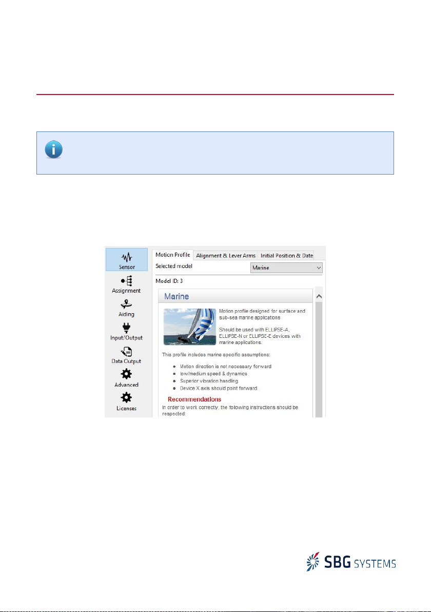
We recommend using the sbgCenter to configure the products, but this is also possible by
using our sbgECom C library.
Mechanical installation
Inertial Systems are very sensitive to their environment and the location of the inertial system
into the vessel is a key point to get accurate and reliable measurements.
Vibrations
The Ellipse is designed to handle vibrations. Nevertheless in case of highly vibrating
environment, an efficient mechanical vibration isolation is required for proper operation. Silicon
dampers can be used for that purpose.
Ellipse placement in the vessel
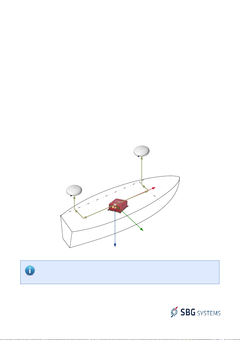
The vehicle coordinate frame is defined as follows:
●X axis points to the front of the vessel (bow)
●Y axis points to the right (starboard)
●Z axis points the bottom (keel)
The Ellipse MUST be mechanically aligned with the vehicle
coordinate frame, as explained in the following diagram.
Alignment accuracy should be better than 1°.
Note: If a correct mechanical alignment is not possible, then a software alignment
can be used. lease refer to the Ellipse User Manual for such operation.
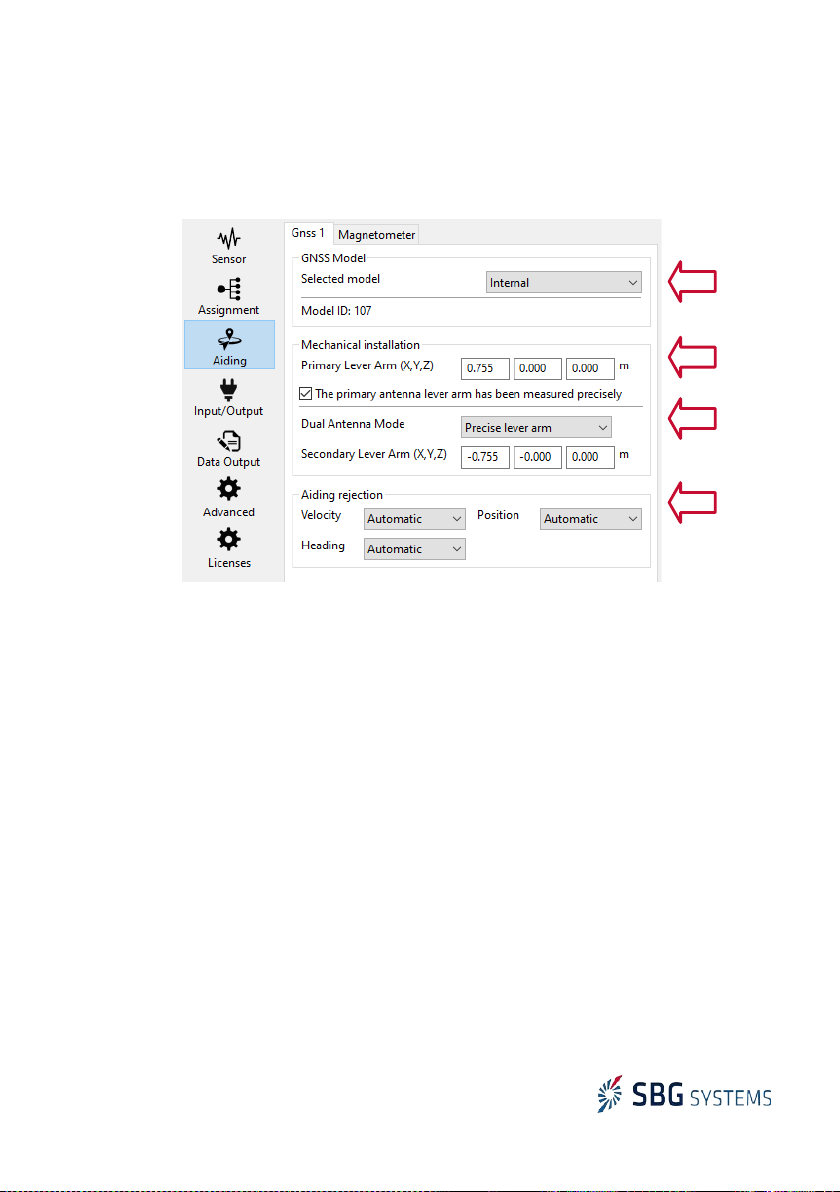
The main lever arm is the signed distance,
expressed in the vehicle coordinate frame,
FROM the Ellipse center of measurements TO
the vehicle desired measurement point. It can
be used to deport the velocity and position
outputs to this specified location.
Only velocity and position outputs are
affected by this main lever arm measurement.
2/9