Elmdene QUARTZ-1000-G2 User manual

Technical Support Line +44 (0)23 9269 6638 (Option 3) PAK200360 I 03B Mar 2012 ©2012 ELMDENE INTERNATIONAL LTD
QUARTZ Range
External Sounder
Models
QUARTZ-1000-G2, QUARTZ-3000-G2
F
EATURES
-
High Efficiency Operation
-17mA tandby,
-130mA ounding
-Silent Engineer Start-up
- Selectable ound auto cut=off timer
-Selectable SAB or SCB operating mode
-
Integr
al
1 Watt
Xenon tube trobe
-Active inru h current limit on trobe
-Strobe Power Save Mode
-Fla hing Comfort LED
-Microproce or controller
-Enclo ed electronic module
Elmdene International Ltd
Tel: +44(0)23 9269 6638
3 Keel Close, Interchange Park, Fax: +44(0)23 9266 0483
Portsmouth, Hampshire, PO3 5QD, UK
Web: www.elmdene.co.uk

Technical Support Line +44 (0)23 9269 6638 (Option 3) PAK200360 I 03B Mar 2012 ©2012 ELMDENE INTERNATIONAL LTD
O
ERATION
The Quartz ounder i u ed for notification of an alarm condition a generated within an intruder, hold-
up or other alarm y tem. In re pon e to command from the alarm y tem control panel, the Quartz will
emit a high inten ity ound and/or operate a vi ual fla h.
The Quartz will detect any attempt to gain unauthori ed acce to the ounder by removal of the cover,
or any attempt to remove it away from it mounting urface. Thi will generate a tamper ignal which i
normally fed back to the alarm control panel.
The Quartz i cla ified a elf powered ounder and ha an on-board battery which i recharged via the
external power ource. Thi battery i u ed to operate the ounder if the external power i removed. The
Quartz can be configured to elf actuate (SAB Mode ON) in the event that a tamper condition i detected
or the external power to the ounder i removed.
To a i t with commi ioning, the Quartz ha an Engineer Mode to provide ilent tart-up. Two Comfort
LED are u ed to provide a heart-beat type vi ual indication when the Quartz i not ounding.
F
UNCTIONAL
I
NFORMATION
Tamper Circuit for Single or Multiple Cascade Installations
For ingle ounder in tallation link TS to H- and connect TR to the control panel Tamper Return input.
(See Fig. 2).
In ca cade in tallation with two or more ounder , the TS (Tamper Source) will normally be connected
to the TR (Tamper Return) of the next ounder except for the la t unit which will have TS linked to H-.
(See Fig. 3)
Engineer Mode
Thi elect ilent tart-up and ilent maintenance. The ENG input may be brought back to the control
panel and connected to a programmable output. Switching thi control panel output high when
maintenance i required will prevent the ounder from elf activating when the cover i removed or R-
activated. The Tamper output i open when ENG i high, thi prevent inadvertent y tem etting with
the ounder left in Engineer Mode (when SAB Mode = on).
O
TIONS
S
ELECTION
Sound Cut-off Timer
The Quartz ounder will automatically top ounding after the time period elected by the Sound Cut-off
Timer link, Figure 11, irre pective of the tatu of the ound trigger (R-) input. The 5 option i provided
to reduce nui ance noi e during te ting.
SCB/SAB Mode
In SAB mode the ounder can draw current from both the control panel and the battery. The iren will
elf-activate if either of the tamper are activated.
In SCB mode the ounder draw the majority of it current from the battery to minimi e drain on the
control panel. Thi allow the u er to connect multiple unit to a control panel without overloading it.
Select SCB mode u ing the link next to the terminal block (Figure 1.0). In thi mode the ounder will NOT
elf activate under a tamper condition but the tamper condition will till be ignalled back to the control
panel. The control panel can then trigger the iren u ing the R– line.
Note: The iren will elf-activate if the upply line are cut in either mode.
2

Technical Support Line +44 (0)23 9269 6638 (Option 3) PAK200360 I 03B Mar 2012 ©2012 ELMDENE INTERNATIONAL LTD
Figure 1: Jumper Link options
C
ONNECTIONS
BT+ Po itive connection to battery.
BT- Negative battery connection. Connect black battery lead after power i applied.
ENG Optional engineer input for quiet operation during in tallation or
maintenance. In engineer te t mode apply a po itive ignal to
prevent elf activation of iren by tamper condition (e.g. lid open).
H+ Permanent po itive hold-off upply.
H- Permanent negative hold-off upply.
TS Tamper ource: Connect to H– for ingle unit or la t in line. Connect to TR of next unit for
multiple unit in tallation ( ee Figure 3.0)
Note each siren has a tamper resistance of 100Ω.
TR Tamper return connection to control panel. ( ee Figure 2.0 and 3.0)
R- Negative iren trigger.
ST- Negative trobe trigger and upply.
3

Technical Support Line +44 (0)23 9269 6638 (Option 3) PAK200360 I 03B Mar 2012 ©2012 ELMDENE INTERNATIONAL LTD
Fig 2: Single Quartz Tamper Connection
ENG
H+
H-
TS
TR
R-
ST-
TAMP
IN
ST-
R-
H-
H+
TS
ST-
TR
R-
H-
H+
ENG
CONTROL PANEL
UNIT 1
UNIT 2
Fig 3: Multiple Cascade Quartz Tamper Connection
4

Technical Support Line +44 (0)23 9269 6638 (Option 3) PAK200360 I 03B Mar 2012 ©2012 ELMDENE INTERNATIONAL LTD
I
NSTALLATION AND
S
ET
-U
1. Select a uitable mounting po ition for the Quartz ounder.
2. Drill hole a required for fixing the backplate to the wall and for cable entry to the rear of the unit.
3. Fit tamper extender (if required), and trim to de ired length:
4. Route cable from control panel through cable entry cowl.
5. Fit backplate to wall u ing minimum of 3 x No. 10 fixing crew uitable for material of mounting
urface.
TAMPER
EXTENDER
PARKING
COVER SCREW
PARKING
LOOP CABLE
UNDER CABLE
CLAMP
5

Technical Support Line +44 (0)23 9269 6638 (Option 3) PAK200360 I 03B Mar 2012 ©2012 ELMDENE INTERNATIONAL LTD
C
OMMISSIONING
1) Fit timer link to elect 5 ound -off time.
2) Fit link to elect SCB or SAB mode a required.
3) Connect ENG input to H+ or to a witched output of control panel et high.
4) Apply power to the ounder via H+ and H- from control panel.
5) Connect R-, ST- and TR to their re pective output on the control panel.
6) Connect the black battery lead to BT- ( lide leeve to expo e conductor).
7) Check tamper ignal i pre ent at control panel (circuit open). Thi verifie the ENG function.
8) Di connect ENG input (or witch low from panel). Note: Sounder will operate
9) Fit cover. Sounder will top. Thi verifie the tamper operation.
10) Check tamper ignal i removed at control panel (circuit clo ed).
11) Te t ounder by triggering R- input.
12) Te t trobe operation by triggering ST- input.
13) Remove cover. Note: Sounder will operate and a tamper will be signalled to the control panel.
14) Remove timer link to elect 15min ound -off time.
15) Re-fit cover and ecure u ing fixing crew .
16) Di connect H+ and check that the iren activate . Re tore H+.
17) Di connect H- and check that the iren activate . Re tore H-.
18) Commi ioning complete.
M
AINTENANCE
The Quartz ounder hould be te ted for correct operation on a periodic ba i . A minimum of one
check every 12 month i recommended. The following feature hould be verified on each
maintenance vi it:
1) Correct operation of ounder and trobe from control panel ignal
2) Correct operation of cover and rear tamper .
3) Remove the H+ upply from the control panel and check that the internal battery voltage a
mea ured between BT+ and BT- i greater than 6.0v dc. If the battery voltage i le than thi
value replace the battery and re-connect ob erving CORRECT polarity.
4) Check for ign of ignificant water or in ect ingre . Clean a nece ary.
SAB
B
ATTERY
R
EMOVAL
The SAB battery may be removed for di po al at end of product life or if it i detected faulty when
te ted ( ee Maintenance above). To remove the battery, di connect red and black lead from BT+
and BT- and unclip battery from holder. To fit a new battery, clip into holder, route battery cable
around clip and reconnect po itive (RED) lead to BT+ and negative (BLACK) lead to BT-.
IMPORTANT: En ure correct polarity of connection and that expo ed battery lead DO NOT
accidentally touch.
Dispose of used batteries in accordance
with all national and local regulations
6

Technical Support Line +44 (0)23 9269 6638 (Option 3) PAK200360 I 03B Mar 2012 ©2012 ELMDENE INTERNATIONAL LTD
F
AULT
F
INDING
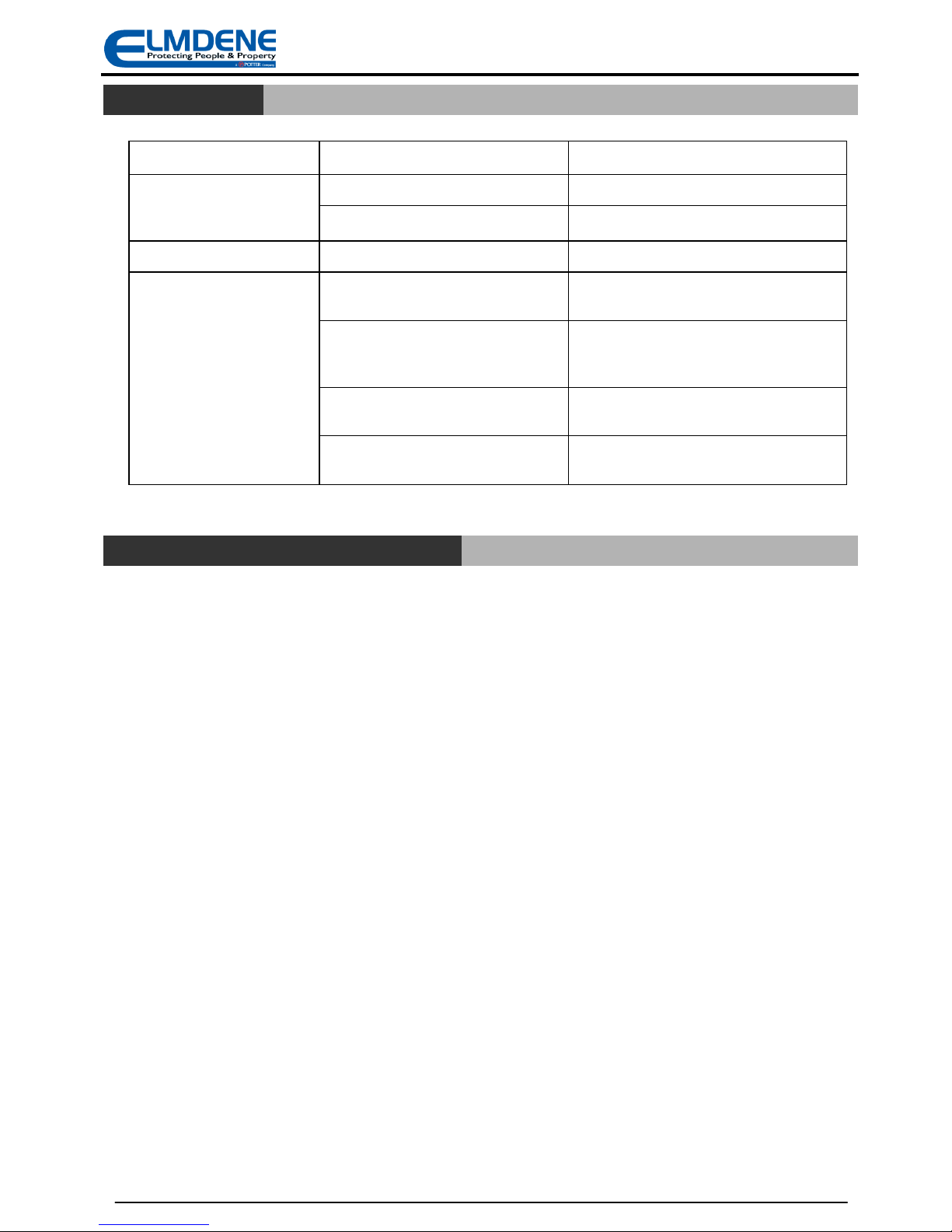
Symptom Fault Action
Sounder activated in non-
alarm condition and tamper
how at panel
Cover not clo ed correctly. Check cover clo ed and crew ecure.
Rear tamper pin not correct length Correct rear tamper pin length.
Sounder top after 5 Incorrect timer link etting Set correct timer jumper link .
Cannot SET control panel
(due to ounder tamper)
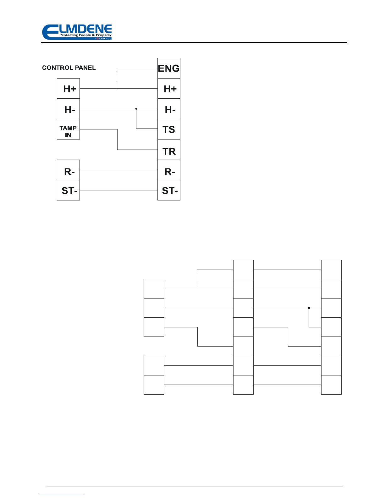
Tamper output open due to ENG input
till connected to H+
Di connect ENG from H+ in ounder or et
control panel programmable output low.
Tamper Source (TS) not connected to
H- for ingle ounder or to Tamper
Return (TR) for ca caded ounder
Refer to connection diagram for ingle
and ca caded ounder (Figure 2 and 3).
Total re i tance of tamper circuit too
high for multiple ounder in tallation
Reduce number of ca caded ounder on
one tamper loop.
Cover or Rear tamper witch not
clo ed.
Check cover and rear tamper witche fully
clo ed.
D
IS OSAL OF
RODUCT AT
E
ND OF
L
IFE
Thi product fall within the cope of EU Directive 2002/96/EC Wa te Electrical and Electronic Equipment
(WEEE) and 2006/66/CE (Battery). At the end of life, the product mu t be eparated from the dome tic
wa te tream and di po ed via an appropriate approved WEEE di po al route in accordance with all
national and local regulation .
Before di po al of the product, the SAB battery mu t be removed and di po ed eparately via an
appropriate approved battery di po al route in accordance with all national and local regulation . Package
u ed batterie afely for onward tran port to your upplier, collection point or di po al facility.
Caution risk of fire or explosion
if bare battery wires are allowed to touch.
See Specification for battery type information. The battery i marked with the cro ed out wheelie bin
ymbol, which may include lettering to indicate cadmium (Cd), lead (Pb), or mercury (Hg).
For more information ee: www.recyclethi .info
7

Technical Support Line +44 (0)23 9269 6638 (Option 3) PAK200360 I 03B Mar 2012 ©2012 ELMDENE INTERNATIONAL LTD
S
ECIFICATION
Sounder Volume 105 dB(A) single piezo (QUARTZ-1000-G2)
108 dB(A) dual piezo (QUARTZ-3000-G2)
Cut off Timer 15 minutes max (5 second test)
Waterproofing All electronics conformal coated
Operating Temp -25 to + 60 °C
Storage Temp -25 to + 70 °C
Supply Voltage
9—15V d.c. (13.8 V d.c. nominal)
Current
15 mA max. Quiescent
130 mA max. Sounder
120 mA max. Strobe
Battery
Type Ni-MH
Voltage 6.0V
Capacity 320 mAH
Strobe
Rating 1 Watt
Flash Rate 1 Hz reduces to 1/2 Hz after 15 minutes
Comfort LEDs
Alternate flash, 60 per minute
Material 3mm Polycarbonate—all parts
Tamper Detection Cover and Rear
Kinetic Protection IK08
C
OM LIANCE
Thi product meet the e ential requirement of the following EU Directive :
EMC: 2004/108/EC
RoHS: 2002/95/EC
WEEE: 2002/96/EC
Battery: 2006/66/EC
EN50131-4:2009 Security Grade 2
Environmental Cla IV
Thi product i uitable for u e in y tem de igned to comply with PD6662:2010 at:
Grade 2 and Environmental Class IV.
The packaging supplied with this product may be recycled.
Please dispose of packaging accordingly.
8
This manual suits for next models
2
Table of contents
Other Elmdene Marine Equipment manuals
Popular Marine Equipment manuals by other brands

Volvo Penta
Volvo Penta D5A Operator's manual

Furuno
Furuno GP-1650F installation manual

Lopolight
Lopolight 300-138 installation instructions

ECO SISTEMS
ECO SISTEMS Water-pro Compact S-90 12V owner's manual

Raymarine
Raymarine LIGHTHOUSE 4 Operation instructions

KVH Industries
KVH Industries TracPhone F33 user guide