Scalemaster Softline 150 Owner's manual

SOFTLINE 150, 150 MINI & 450
Non - Electric Water Softeners
Installation & Operation Manual Effective: 2021
PLEASE READ FULLY BEFORE INSTALLATION

1
PAGE
Contents
Introduction 2
Features & Benefits 2
Before You Start 3 - 4
Installation
Your Softline Water Softener 5
Installation 6 - 10
Settings 11
Commissioning & Operation 12 - 14
IMPORTANT INFORMATION - PLEASE NOTE:
Before you start installing your Softline Water Softener, ensure that you have all the
correct parts and tools required to install your Water Softener.
YOUR SOFTLINE WATER SOFTENER IS COVERED BY A 5 YEAR PARTS & 2 YEARS LABOUR
WARRANTY. TO ENSURE YOUR WATER SOFTENER IS COVERED IT MUST BE INSTALLED IN
ACCORDANCE WITH THESE INSTRUCTIONS & REGISTERED ONCE INSTALLED.
YOUR WARRANTY DOES NOT COVER RESIN DAMAGE OR DAMAGE TO YOUR WATER
SOFTENER THROUGH INGRESS OF DEBRIS OR CHEMICALS FROM EXTERNAL SOURCES,
INCORRECT INSTALLATION, ON-SITE DAMAGE OR INCORRECT SETTING UP OF THE
UNIT.
In the interests of continuing product development, we reserve the right to make
modifications to the specification of the unit without notice.

2
Thank you for choosing a Softline Non Electric Water Softener.
It is important that you take the time to read this installation guide. It will tell you in a simple
format how to install your Water Softener and how to start enjoying the benefits of
softened water.
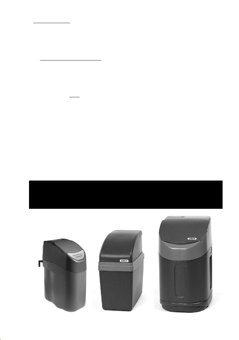
This instruction manual applies to the SL150, SL150 Mini & SL450 models only.
1. Introduction.
The SL Non-Electric range of Water Softeners from Scalemaster present a new approach to
the world of water softeners. Based on proven technology, Because these softeners are
non-electric there are no issues relating to electrical installation compliance. These units
are still fully automatic. The units operate purely through the hydraulic pressure of the
incoming water whether that be from the mains or from a well. Scalemaster non-electric
water softeners have no motors and no wires, they just do not need them! The moving
parts are operated by dynamic water pressure above 1 bar (dynamic).
Scalemaster SL Water Softeners are one of the most efficient water softeners on the
market. For example, through it’s advanced technology, the SL150 version typically uses
only 330 grams of salt and 18 litres of water for every regeneration making it one of the
most environmentally friendly water softeners on the market today. Water usage is less
than 4% per regeneration which meets the minimum performance requirements of the
Code for Sustainable Homes published by the Buildings Research Establishment.
2. Features & Benefits.
• NON-ELECTRIC: The 150 & 450 range work entirely without electricity.
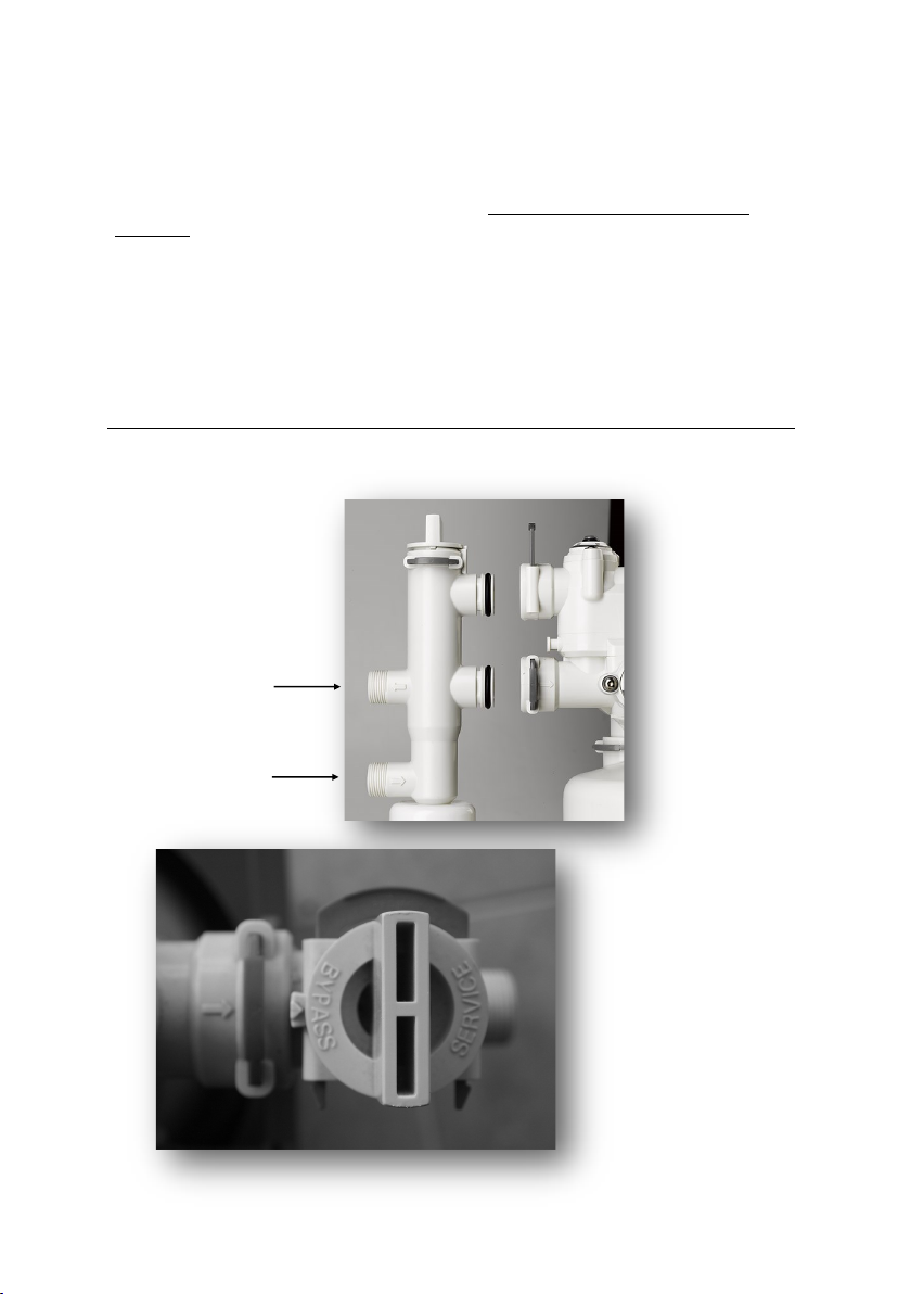
• EASE OF INSTALLATION: Far simpler than standard water softeners to install due to the
simple and unique ‘clip-connect’ design and integrated bypass manifold.
• COMPACT DESIGN: The SL150 is designed to fit into a standard kitchen cabinet and
other areas where space is at a premium.
• MINIMAL PROGRAMMING: Just set the water hardness for your area.
• ENVIRONMENTALLY FRIENDLY: Designed to use minimal salt & water during regenera-
tion.
• HIGH TEST STANDARDS: The units are all ‘wet tested’ before leaving the factory.
• HIGH FLOW RATES: Nominal flow rate (1 bar loss of pressure) 25 litres per minute (1500
litres per hour).
DID YOU KNOW?
The salt used in a water softener is not used to soften the water, it’s used
as part of the cleaning process (regeneration) that the softener will go
through periodically.

3
3. Before You start
• Make sure you have all necessary parts and tools required before starting the
installation.
• Follow all regulations regarding drainage. If in doubt see the relevant WRAS
guidance notes which can be found at www.wras.co.uk.
• Read this manual carefully. If you have any questions please contact the
Technical Helpline on 07990 064096.
• Check incoming water pressure: minimum 1 bar (dynamic), maximum 6 bar
(static) (15 - 100 PSI). If necessary fit a pressure reducing valve to reduce the
incoming water pressure.
• Do not install the water softener close to a heat source. (environment ambient
temperature must be below 40°c ).
• Protect the water softener drain hose (item 11, page 5), and all fittings against
frost.
• Make sure you have tested the water for Total Hardness for the area. If in doubt
telephone the Technical helpline on 07990 064096 to obtain this information.
• Remember, if you are not sure ASK!
It is recommended that any water softener is installed by a professional.
Although Softline water softeners are probably the easiest and safest softener on
the market, it is imperative that all necessary precautions are taken.
This installation guide is written to help the professional installer and assumes that this
person has a working knowledge of hydraulic softeners and domestic plumbing.
Proper operation of the softener depends on correct installation,
commissioning, maintenance and maintaining the salt level with suitable
salt manufactured for use in water softeners.
Identification of your Water Softener
Softline SL150 Mini Softline SL150 Softline SL450

4
3.1. Positioning the water softener
• Remember to measure your water softener and the space where it will be installed.
Remember to allow extra space for connecting pipework when you do your
calculations along with adequate space to allow for future servicing, maintenance
and topping up of salt.
• Keep the distance of the incoming main and drainage to a minimum. While 2 metres is
an adequate distance this can be longer in circumstances where water pressure
allows.
• The weight of the water softener is greatly increased when fully operational and filled
with both salt and water so this must be taken into account when choosing where to
site the water softener.
• Your water softener is designed to operate effectively with an incoming water pressure
of between 1 bar and 6 bar. If your water supply is likely to fall outside of these param-
eters we recommend that either a booster pump or pressure reducing valve should be
fitted accordingly.
• Do not install your water softener next to a boiler or other heat source that will exceed
ambient temperature of 40°c.
IF YOU ARE CONSIDERING INSTALLING YOUR WATER SOFTENER IN A LOFT, THE FOLLOWING
INSTRUCTIONS SHOULD BE STRICTLY ADHERED TO.
3.2. Loft Installation
• The water softener may be installed in a loft or roof cavity but must be situated within a
safety tank of not less than 100 litre capacity. A suitable tank would be a plastic roof
storage tank with an overflow pipe of not less than 20mm diameter. This tank should be
mounted on a board strong enough to spread the weight over a load bearing wall.
3.3. Drinking Water
• When fitting your water softener allowance should be made for at least one drinking
water tap that is not fed by the water softener. Where practical this should be at the
kitchen sink but a utility room or other suitable alternative will suffice.
• It is recommended that people on a low sodium diet should not drink artificially sof-
tened water. Water used for mixing infant powder for babies must only be taken from
unsoftened water as artificially softened water contains an increased level of sodium
to which young babies have a limited tolerance.

5
1. Bypass Manifold 8. Blending Regulator (Always left at 0)
2. Valve Housing 9. Water Hardness Regulator
3. Resin Vessel 10. Brine Pick-Up Tube
4. Salt Chamber 11. Discharge Connector to Drain
5. Brine Float Assy (Under Lid) 12. Pre Drilled Overflow (3 options)
6. Water Inlet 13. Serial Number (under barcode).
7. Water Outlet
1
2
3
4
6
7
8
9
12
5
10
11 PLEASE NOTE
While the outward appearance of
the 150, 150 mini & 450 are different
the look of the component parts will
look similar or the same as described
on this page.
13

6
4. Installation:
4.1 Close the main valve (stop tap) and make sure pressure is released from the piping.
This can be done by opening at least one tap.
4.2 Cut into the cold water mains supply in order to install two isolation valves, one for
the mains inlet and one for the mains outlet. These are not supplied with the
Softener.
4.3 ENSURE THE BYPASS VALVE IS SET TO “BYPASS” (see bottom picture) Connect the
mains inlet to the bottom port of the bypass unit using the hose supplied and the
mains outlet to the top port of the bypass unit with the remaining hose.
4.4 Connect the bypass unit to the softener, by gently pushing the bypass into the two
ports on the back of the valve ensuring that the inlet filter does not fall out. Insert the
two clips fully to secure the bypass. (note that the 450 has two extenders).
Ensure that bypass is the correct way up with the Service / Bypass knob at the top.
OUTLET
INLET
NOTE:
When ‘BYPASS’ is facing the
arrow (as in the picture) the
softener is isolated from the
mains water supply.
BYPASS = OFF
SERVICE = ON

7
4.5 Connect the straight drain outlet (part 11. page 5) to a local drain by means of
the 13 mm flexible drain hose supplied in the installation kit. ENSURE THE HOSE IS
FULLY PUSHED ON TO THE STRAIGHT DRAIN OUTLET. This drain pipe has been
reinforced to avoid possible problems caused by kinking of the pipe. IT IS
IMPORTANT HOWEVER TO PROTECT THE DRAIN HOSE FROM FROST & EXCESSIVE
HEAT. If the drain hose is being taken outside ensure a suitable insulation material
is used to stop water freezing in the pipe. (min. temp. 5°c, max. temp. 40°c).
NOTE: The discharge drain hose may installed with a rise of up to 1m but this
must be over a 5 metre run.
CAUTION: Follow all regulations regarding connection of the flexible drain
hose to the drain. If in doubt check the relevant WRAS guidance notes at
www.WRAS.co.uk
STRAIGHT DRAIN
OUTLET - DO NOT
CONNECT THE
DISCHARGE TO
THE OVERFLOW!
Maximum height and distance of flexible drain hose
5m
1m

8
4.6 Connect the brine float assembly (part 5, page 5) to the softener by means of the
4mm flexible tubing. Insert the tube as far as possible (to stop) into the quick release
couplings. Make sure not to squeeze the tube and avoid kinks.
4.7 Install the supplied overflow fitting. Remove one of the 3 rubber plugs in the salt
cabinet. Insert the overflow fitting and secure it from inside the salt cabinet with the
supplied nut and washer. Connect the pipework so that any overflowing water runs
downhill to drain or through an outside wall. Do not connect the overflow to the
discharge connector.
NOTE:
The 13mm Flexible hose is supplied in 1 piece which can be cut as
required for use on the discharge and the overflow.

9
4.9 On the SL150 the valve & vessel can be installed in the salt container in three
different orientations: with the bypass at the back, to the left, or to the right simply
by rotating the base plate so that the arrow faces the direction required, right, left
or to the back. (installation on the SL150C, SL150 Mini and the SL450 is to the rear
only).
4.8 Place the softener (valve & vessel) in the salt bin; use the side with the round
opening (for correct installation, see 4.9). To install the brine float assembly, open the
small hinged lid (open by pressing gently on both sides) Insert the brine float
assembly inside the space provided, ensuring that it is the correct way up (see
diagram below). The brine float should be gently pushed all the way to the bottom
of the channel and the tube fitted so as to go behind the blue bar (see below).
Left Hand Install* Rear Install* Right Hand Install*
*IMPORTANT: if the brine float assembly
is inserted upside down or not pushed to
the bottom of the channel, the water
softener will not work.
*SL150 ONLY

10
5. Settings:
5.1 THE HARDNESS REGULATOR: (Part 9, Page 5).
The hardness regulator is situated on the TOP of the valve unit and has measurements
marked 0 through to 600. Measure the incoming water by means of one of the test
strips provided. (these are on the reverse of the registration card) The Softline units use
ppm (parts per million) settings of CaCO3.
Adjust the hardness regulator to the measurement value using the 5mm hex key
supplied. Do not force the dial in the wrong direction. If you are unsure contact the
Technical Helpline.
5.2: THE BLENDING REGULATOR: (part 8, page5).
The blending regulator is situated on the SIDE of the valve unit and has measurement
markings from 0 through to 1/2 in fraction increments.
THE SETTING OF THE BLENDING REGULATOR SHOULD BE LEFT AT ZERO.

11
6. Commissioning & Operation
6.1 Leaving the water softener in ‘bypass’ mode, open the main valve (stop tap)
slowly and flush for several minutes in order to avoid any debris from installation
entering the water softener.
6.3 Now add salt into the salt container
(indicated) salt may be filled to the
height of the overflow.
6.2 Add water to the salt container unl
the water level is approx, 10cm (4”)
high.
6.4 Turn the bypass fully 180° slowly into
“service” mode.
THE SL150 WILL USE EITHER GRANULES, TABLETS OR BLOCK SALT.
THE SL150 Mini & SL450 USED EITHER GRANULAR OR TABLET SALT.
FOR THE BEST PERFORMANCE WE WOULD RECOMMEND TABLET SALT.
ALWAYS USE SALT THAT HAS BEEN SPECIFICALLY FORMULATED FOR USE IN WATER
SOFTENERS. (IF IN DOUBT CONSULT YOUR SUPPLIER)

6.5 Turn on the first cold water tap after the water softener so a flow runs through
the water softener. Some air may flow from the tap, this is normal as excess air is
purged from the water softener, this will happen only once at start up.
Because the water softeners are ‘wet tested’ before leaving the factory there
may also be a discolouration to the water when the tap is turned on for the first
time, again this is normal and will clear after the water has been run for a few
minutes.
When only clear water flows from the this tap, close the tap.
6.6 Perform a manual regeneration. Follow steps 6.6 (a) - 6.6 (c)
6.6 (a) Use the 5mm hex key supplied to turn the programme disc (shown in
diagram 1 below).
Turn the programme disc slowly counter clockwise until it is in the
position shown in diagram 2 below. When the arrow and the small line
on the transparent cover reach the area marked ‘B’ (brining), the
regeneration will start.
Immediately, the programme disk will drop down slightly (you will be
able to see and hear this) at this point you will hear or see a trickle of
water going to drain and the water level in the container will start to
drop.
About 3/4 through the regeneration you will hear a change in tone as
the programme disc reaches ‘R’ (refill) and the softener refills the
container with approx. 1 litre of water ready for the next regeneration.
At this point the water in the salt tank will rise slightly.
6.6 (b) Finally, at the end of the regeneration cycle you will hear the water go
to drain and then stop. This is a clear indicator that the regeneration
stage is over. Depending on water pressure the regeneration cycle will
last about 12 minutes.
6.6 (c) Check outgoing hardness with the second hardness test strip provided.
Test the water at the first cold water tap after the softener.
12
DIAGRAM 1

6.7 Place both lids on the container. (SL150 Mini & SL450 have a sliding cover).
First the valve cover; making sure the connections fit in the large opening and the
drain in the small opening. (if the valve cover does not sit correctly check the
position of the base plate). (see 4.8, page 10).
Then replace the front lid. For future salt refills, only the front lid has to be
removed.
For ongoing operation, add salt to the container when it gets low. Do not allow
the salt level to drop below the level of the water in the salt cabinet and do not
allow the salt container to become drained of salt completely as this will impair
the performance of the unit and its long term ability to provide soft water.
REMEMBER -
TO BENEFIT FROM THE WARRANTY ON YOUR WATER SOFTENER YOU MUST REGISTER
IT. YOU WILL NEED THE SERIAL NUMBER WHICH YOU WILL FIND ON A BARCODE
STICKER ON THE SIDE OF THE VALVE.
DO NOT FORGET TO CONNECT THE OVERFLOW TO A SUITABLE DRAIN
ALSO ENSURE THAT THE REGISTRATION FORM IS COMPLETED AND
RETURNED TO THE ADDRESS ON THE CARD TO ENSURE YOUR NEW WATER
SOFTENER IS COVERED WITH OUR 5 YEAR PARTS AND 2 YEAR LABOUR
WARRANTY
- YOU CAN ALSO REGISTER YOUR WATER SOFTENER ONLINE -
Congratulations and welcome to the benefits of
quality softened water!
13

14
IMPORTANT NOTES
YOUR SOFTLINE WATER SOFTENER BENEFITS FROM A 5 YEAR PARTS
& 2 YEARS LABOUR WARRANTY.
FAILURE TO ENSURE THE FOLLOWING POINTS WILL INVALIDATE YOUR
WARRANTY AND MAY INCUR EXTRA COST FOR CALLS MADE BY
SCALEMASTER ENGINEERS TO RECTIFY.
THIS INSTRUCTION MANUAL SHOULD BE LEFT WITH THE CUSTOMER
FOR FUTURE REFERENCE
DATE INSTALLED
✓
1Are all grey clips fully secure ?
2Is the Brine Float assembly correctly installed ?
3Is the Bypass the correct way up ?
4Is the Water Hardness regulator set correctly ?
5Is the Blending Valve set to Zero ?
6Are all hoses installed correctly ?
7Has the Water Soener been registered ?
8Has the customer been shown fully how to operate the Water Soener?
9Has the customer been shown how to isolate the unit in an emergency ?
IMPORTANT INFORMATION TO THE OWNER:
• Always use water softener grade salt.
• Do not overfill the water softener with salt.
• Do not fill the salt cabinet higher than the overflow.
• Do not let the softener run out of salt.
• The water softener does not make a noise when operating normally
(not regenerating).
• Do make sure you know how to bypass the water softener in an
emergency.
Other manuals for Softline 150
1
This manual suits for next models
2
Table of contents
Other Scalemaster Water Dispenser manuals
Popular Water Dispenser manuals by other brands

Everpure
Everpure Water Filter and Cartridge QL2-OW200L Specification sheet

CSI
CSI Signature 2 Series Installation & operation manual

Curtis
Curtis Igloo MWC519 Product features

Addie Water Systems
Addie Water Systems 6700 Service manual

Pentair
Pentair NS3-P manual

Black & Decker
Black & Decker 900142 user manual