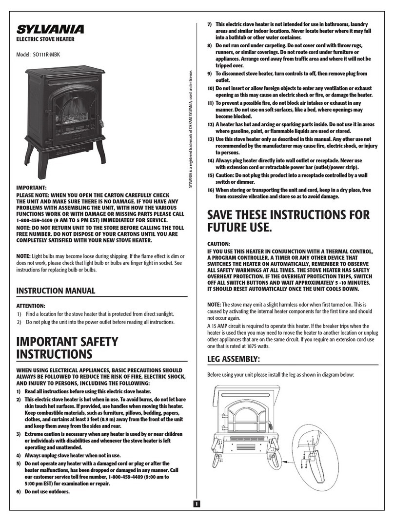
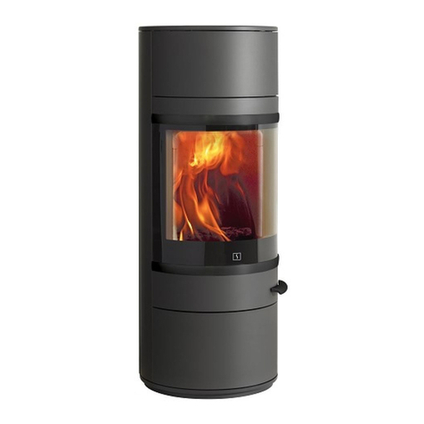
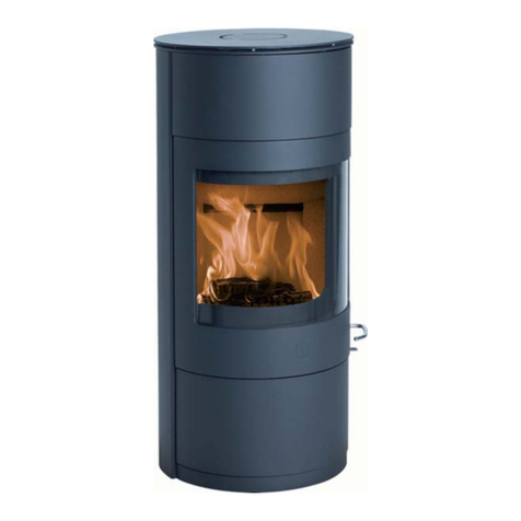
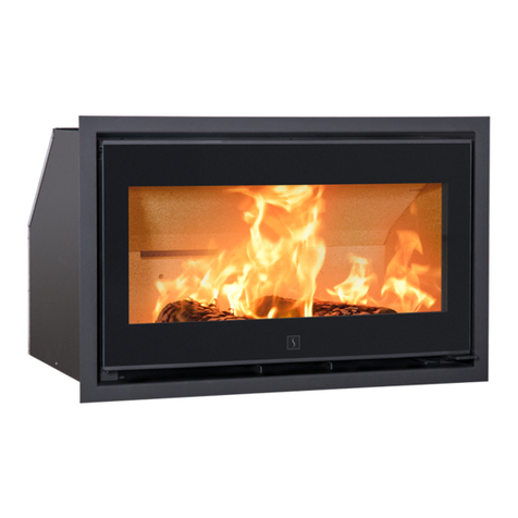
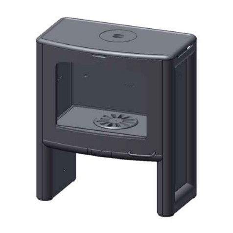
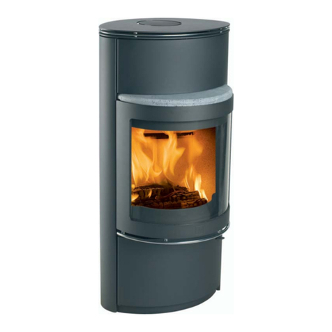
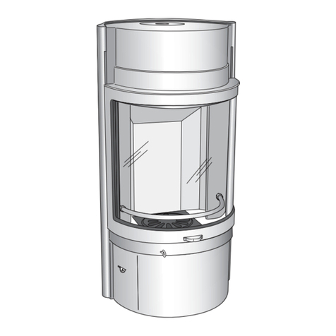
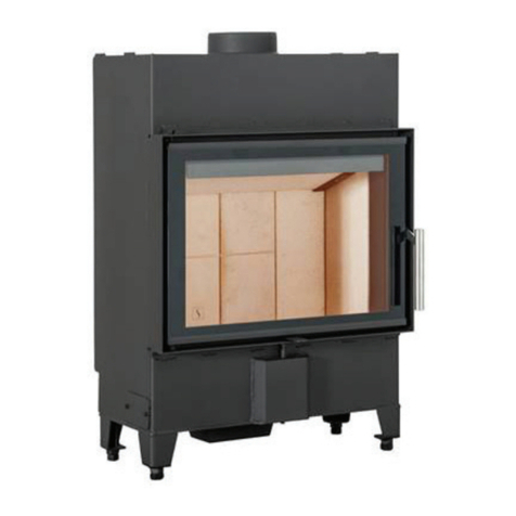
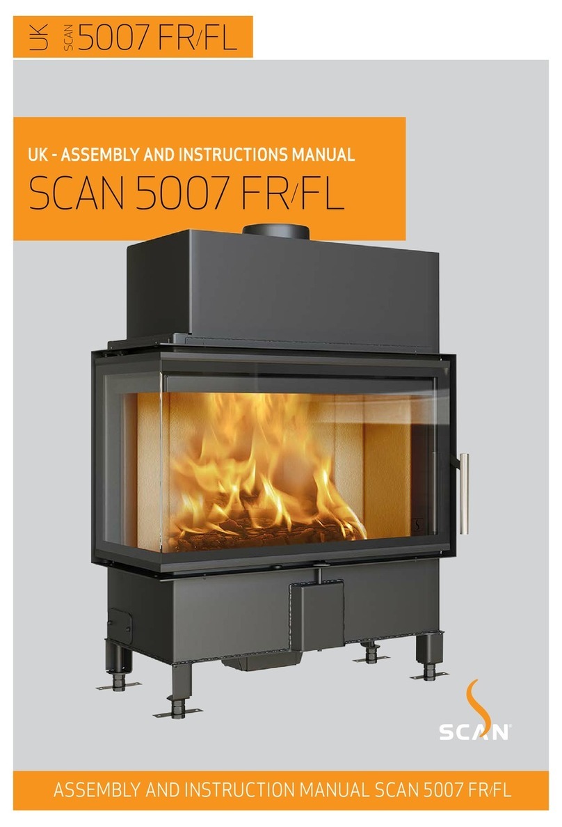
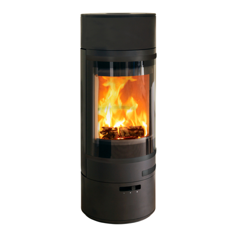
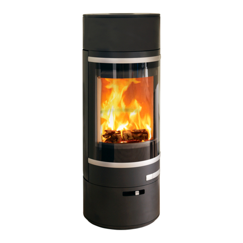
SCAN 5006 FR User guide

5006 FR/FL
UK
SCAN
ASSEMBLY AND INSTRUCTION MANUAL SCAN 5006 FR/FL
UK - ASSEMBLY AND INSTRUCTIONS MANUAL
SCAN
5006 FR/FL

5006 FR/FL
2
You have purchased a product by one of Europe’s leading manufacturers of wood-burning
stoves, and we are sure that you will have years of pleasure from your purchase.
To make the best possible use of your stove, it is important that you follow our advice
and instructions. Read through this Assembly and Instruction Manual carefully before
you start to assemble your stove.
UK
SCAN
CONGRATULATIONS
ON YOUR NEW SCAN
BUILT-IN STOVE
SCAN 5006 FL
SCAN 5006 FR

3
CONTENTS
¬¬
TECHNICAL DATA 4
Installation 4
Safety 4
Technical data and dimensions 5
Dimension sketch and minimum distances 6
Type plate 8
Product registration number 8
¬¬
ASSEMBLY 9
Additional accessories 9
Disposal of packaging 9
Load-bearing foundation 9
Floor plate 9
Existing chimney and pre-fabricated element chimney 9
Connection between built-in stove and steel chimney 9
Requirements for chimney 10
Balanced flue 10
Trim 10
Internal installation in non-flammable material 10
Minimum distance to flammable materials 10
Building in the stove at a fire wall 10
Safety distance 10
Cutout in the surround material 11
Fresh air intake 12
Closed combustion system 12
Fresh air box for floor 12
Clips for Norway (Large rooms) 13
Heat-storage system 13
Mounting of the heat shields/convection covers 14
Frames 18
Convection air 21
Mounting of convection grate 21
¬¬
INSTRUCTIONS FOR USE 22
Baffle plates 22
Ash container 22
Combustion air 22
¬¬
INSTRUCTIONS FOR HEATING 23
Environmentally friendly operation 23
Lighting 23
Using the stove in various weather conditions 23
Continuous operation 24
Warning about over-firing 24
Firing in the spring or autumn 24
General notes 24
The function of the chimney 24
Chimney fire 24
¬¬
HANDLING OF THE FUEL 25
Selecting wood/fuel 25
Preparation 25
Storing 25
Moisture 25
Use of the following as fuel is illegal 25
Calorific value of the wood 25
¬¬
MAINTENANCE 26
Sweeping the chimney and cleaning the stove 26
Checking the stove 26
Servicing 26
Combustion chamber lining 26
Gaskets 27
Painted surfaces 27
Cleaning the glass 28
Disposal of stove parts 28
¬¬
TROUBLESHOOTING 29
¬¬
WARRANTY 30

4
YOU GETTHE BEST USE OF
THE STOVE BY USING
A TOP-DOWN
LIGHTING METHOD
SEE
"INSTRUCTIONS FOR HEATING"
PLEASE NOTE!
TECHNICAL DATA
INSTALLATION
¬ The house owner is responsible for ensuring that installation and assembly are in accordance with national and local building
regulations as well as the information provided in this Assembly and Instructions Manual
¬ When you install any kind of fireplace or stove, you must inform the local building and housing authorities. In addition you are
obliged to have the installation inspected and approved by a local chimney sweep prior to commissioning
¬ To ensure best-possible functionality and safety for your installation, we advise you to call a professional fitter. Your Scan
dealer will be able to recommend a qualified fitter in your area. For information on Scan Dealers, please go to
www.scan-stoves.com
SAFETY
Any changes made to the product by the dealer, fitter or user could result in the product and safety functions not functioning as
intended. The same applies to the fitting of accessories or extra equipment not supplied by Scan A/S. This could also be the case
if parts that are necessary for the operation and safety of the stove are dismantled or removed.

5
TECHNICAL DATA AND DIMENSIONS
Test in compliance with EN 13229
CO Emission at 13% O20,0856 %
CO Emission at 13% O21070 mg/Nm3
Dust @ 13% O238 mg/Nm3
Nox@ 13% O299 mg/Nm3
Efficiency 83,56 %
Energy efficiency index 111
Energy efficiency class A+
Nominel output 4,5 kW
Chimney temperature EN 13229 202 °C
Temperature in flue conn. piece 242 °C
Amount of smoke 4,6 g/sek
Sub-pressure EN 13229 11 Pa
Recommended sub-pressure in
connecting piece 16-20 Pa
Required combustion air supply 14,2 m3/h
Fuel Wood
Fuel consumption 1,4 kg/h
Amount of fuel required to light 1,4 kg
Amount of fuel, max. 2,0 kg
Materials
Steel plate
Cast iron
Galvanised sheet
Chamotte
Surface treatment Senotherm
Max. log length 33 cm
Weight Scan 5006 FR/FL 100 kg
Weight Scan 5006 FR/FL
w/heat shield 112 kg
Flue conn. piece internal diameter 132 mm
Flue conn. piece external diameter 149 mm
Approval type Intermittend*
* Intermittent operation in this context means normal use of
a built-in stove. In other words, you should let the fire die
down until only the embers are left before refuelling.
This built-in stove is produced in accordance with type
approval for the product, which also covers the product’s
Assembly and Instruction Manual.
The Declaration of Performance (DoP) is available from
www.scan-stoves.com

Stove:
Path:
Articlenumber:
Material:
Date:
Constructed/Changed by:
SCAN A/S
DK-5492 Vissenbjerg©
Drawing
number:
Name:
C:\Working Folder\Designs\Scan 5006\95006001.idw
95006001
Målskitse, FR 16-04-2020
KEN
Scan 5006
Weight: Area:
N/A N/A
*Note: Refer to the manual
for distance to combustible floor.
937
500
939
115
276-326*438
161
375
900
900
360°
*
***
Stove:
Path:
Articlenumber:
Material:
Date:
Constructed/Changed by:
SCAN A/S
DK-5492 Vissenbjerg©
Drawing
number:
Name:
C:\Working Folder\Designs\Scan 5006\95006002.idw
95006002
Målskitse, FR, varmeskjold til brandmur 16-04-2020
KEN
Scan 5006
Weight: Area:
N/A N/A
*Note: Refer to the manual
for distance to combustible floor.
1031
500
939
115
276-326*438
175
389
539
NAVN:
STI:
DIMENSION:
MATERIALE: DATO: SIGN:
Krog Iversen & Co A/S
DK-5492 Vissenbjerg©
TG.NR:EMNE:
C:\Working Folder\Designs\Scan 5003\95003072.idw
95003072
Gulvplade (afstand til brændbart)
31-03-2020 KEN
Scan 5003-S
VÆGT:
AREAL:
10,10 kg
1349432 mm^2
Y
X
800**
Stove:
Path:
Articlenumber:
Material:
Date:
Constructed/Changed by:
SCAN A/S
DK-5492 Vissenbjerg©
Drawing
number:
Name:
C:\Working Folder\Designs\Scan 5006\95006002.idw
95006002
Målskitse, FR, varmeskjold til brandmur 16-04-2020
KEN
Scan 5006
Weight: Area:
N/A N/A
*Note: Refer to the manual
for distance to combustible floor.
1031
500
939
115
276-326*438
175
389
539
*
***
6
Floor plate
All distances are in mm.
All distances are minimum distances
* Connection of fresh-air intake - inside measure: Ø 108 mm - outside measure: 125 mm
** Min. distance to furniture/flammable material
*** Height to the beginning of flue connecting piece at top/rear outlet,
flue conn. piece - inside measure: Ø132 mm - outside measure: Ø149 mm X / Y according to national laws and regulations
Flammable material
Radiation zone
Scan 5006 Scan 5006 with heat shield to fire wall (Accessory)
DIMENSION SKETCH AND MINIMUM DISTANCES

900
900
360°
NAVN:
STI:
DIMENSION:
MATERIALE: DATO: SIGN:
Krog Iversen & Co A/S
DK-5492 Vissenbjerg©
TG.NR:EMNE:
C:\Working Folder\Designs\Scan 87\90087007.idw
90087007
Opstillingstegning (afstand til brandmur)
02-02-2021 KEN
Scan 87
VÆGT:
AREAL:
N/A
N/A
500
304
680
1480
1693
800
50
NAVN:
STI:
M3 NR.:
MATERIALE: DATO: SIGN:
DK-5492 Vissenbjerg©
TG.NR:EMNE:
C:\Working Folder\Designs\Scan 5003\95003036.idw
95003036
Opstillingsafstand - åben konstruktion
09-10-2018 sr
Scan 5003
VÆGT:
AREAL:
N/A
N/A
DIM.:
Scan A/S
270mm
1000mm
400mm
NAVN:
STI:
M3 NR.:
MATERIALE: DATO: SIGN:
DK-5492 Vissenbjerg©
TG.NR:EMNE:
C:\Working Folder\Designs\Scan 5003\95003003.idw
95003003
Opstillingsafstand
09-10-2018 sr
Scan 5003
VÆGT:
AREAL:
N/A
N/A
DIM.:
Scan A/S
270mm
500mm
350mm
**
**
NAVN:
STI:
DIMENSION:
MATERIALE: DATO: SIGN:
Krog Iversen & Co A/S
DK-5492 Vissenbjerg©
TG.NR:EMNE:
C:\Working Folder\Designs\Scan 87\90087007.idw
90087007
Opstillingstegning (afstand til brandmur)
02-02-2021 KEN
Scan 87
VÆGT:
AREAL:
N/A
N/A
500
304
680
1480
1693
800
50
Min. 500 cm2
Min. 750 cm2
A-A ( 1 : 10 )
A A
NAVN:
STI:
M3 NR.:
MATERIALE: DATO: SIGN:
DK-5492 Vissenbjerg©
TG.NR:
EMNE:
C:\Working Folder\Designs\Scan 5003\95003004.idw
95003004
Opstillingsafstand
26-05-2020 sr
Scan 5003
VÆGT:
AREAL:
N/A
N/A
DIM.:
Scan A/S
100
mm
25 mm
18
Alle mål er minimusmål.
Møbleringsafstand: 800 mm
Brandbart materiale
Brandmur F.eks. 50 mm Jøtul firewall, 110 mm mursten eller
andet materiale med tilsvarende brandfasthed og isolationsevne.
* Afstand til glas
400mm*
7
Flammable material
Fire wall, e.g. 50 mm Jøtul Firewall, 110 mm brick
or other material with corresponding fireproof and
insulating abilities
All distances are in mm.
All distances are minimum distances
These distances apply for an insulated flue pipe all the way down to the stove
* Distance to glass
** Distance to flammable floor
MINIMUM DISTANCES
Building in the Scan 5006 with radiation shields against a flammable wall protected by a fire wall
Installation with an insulated, vertical flue pipe
- structure/surround to ceiling
Installation with an insulated, vertical flue pipe
- open structure/surround
Floor
Ceiling
Lower
convection
opening
Upper
convection
opening
Floor
Ceiling
Insulated length
Cavities are
not to be
filled out
with
insulation
material!

SCAN 5006
- SCAN 5006
206A1X0032
2 / 109915
206A1X0032
8
Type plate Scan 5006 FR/FL
Product registration number Scan 5006 FR/FL
PRODUCT REGISTRATION NUMBER
All Scan built-in stoves are provided with a product registration number. Please make a note of this number at the rear page of
this manual; you will always need to quote it when contacting your dealer or Scan A/S.
The product registration number is placed loose in the fireplace.
TYPE PLATE
All Scan built-in stoves are fitted with a type plate that specifies the approval standards and the distance to flammable materials.
The type plate is placed loose in the fireplace.

9
ASSEMBLY
ADDITIONAL ACCESSORIES
¬ Fresh air box (see page 12) ¬ Connection pipe Ø 100 mm
¬ Heat-storage stones (see page 13) ¬ Heat shields/convection covers (see page 14)
¬ Frames (see page 18) ¬ Convection air grid (see page 21)
¬ Adjustable legs 100 mm and 190 mm ¬ Detachable handle
DISPOSAL OF PACKAGING
Your Scan built-in stove may come supplied with the following packaging:
Wood packaging The wood packaging can be reused and after final use can be incinerated as a CO2neutral
product or sent for recycling
Foam Send for recycling or waste disposal
Plastic bags Send for recycling or waste disposal
Stretch/plastic film Send for recycling or waste disposal
LOAD-BEARING FOUNDATION
All items in our product range come under the category of lightweight fireplaces and stoves and do not normally require any
reinforcement of the beam structure. They can be positioned on ordinary beams/floor.
You should of course make sure that the foundation on which the stove is positioned can indeed support the weight of the stove
and, where applicable, a steel chimney, if you have opted for this solution. In case of doubt about the carrying capacity of the
floor, please consult a building expert.
FLOOR PLATE
If you are placing the stove on a flammable floor, you must comply with the national and local regulations on the size of any
non-flammable subsurface required to cover the floor around the stove.
Your local Scan dealer can advise you on regulations concerning protection of flammable materials in the vicinity of your stove.
The floor plate’s function is to protect the floor and flammable material against any sparks that may occur.
EXISTING CHIMNEY AND PRE-FABRICATED ELEMENT CHIMNEY
If you intend to connect your stove to an existing chimney, it makes sense to contact an authorised Scan dealer, or a local chim-
ney sweep, for advice. These experts will also let you know if your chimney needs renovating.
¬ When connecting a pre-fabricated element chimney, follow the manufacturer’s connection instructions for the
relevant chimney type.
CONNECTION BETWEEN BUILT-IN STOVE AND STEEL CHIMNEY
Your Scan dealer, or local chimney sweep, can advise you on choosing a make and type of steel chimney. This ensures that the
chimney will match your wood-burning stove.

10
REQUIREMENTS FOR CHIMNEY
The chimney must have a minimum internal diameter of 148 mm and have a T400 designation, with G for the soot fire test. The
length should be min. 5 metres.
If you opt to connect the built-in stove with an elbow pipe, you should use a curved elbow, as this gives a better draught.
If you connect the stove with a sharp elbow pipe, the cleansing lid must be placed in the vertical part so that the horizontal part
can be cleaned through here.
If the chimney is fitted with a smoke extractor, it must be possible to adjust it to a suitable draft.
The requirements to the chimney and the flue pipe in terms of safety distances must be met.
¬ Choosing the wrong length or diameter of steel chimney could impair functionality
¬ Always comply exactly with the instructions provided by the steel chimney supplier
BALANCED FLUE
If the stove is connected with a balanced flue, we recommend the use of a 100 mm Lindab tube and a chimney length of min. 5 m.
TRIM
The trim is mounted, when the surfaces of the covering are finished.
INTERNAL INSTALLATION IN NON-FLAMMABLE MATERIAL
When building or fitting into structures that do not contain flammable materials, a minimum distance of 50 mm must be
maintained between the brickwork and the convection hood. This is to prevent cracks in the brickwork caused by the expansion
of the metal while the stove is heating.
MINIMUM DISTANCE TO FLAMMABLE MATERIALS
Distance to side: 400 mm - back: 400 mm - glass: 800 mm. - ceiling: 1000 mm.
You should however assess whether furniture or other items might become excessively dry due to being too close to the stove.
¬ The stove is NOT to be built into flammable materials without the use of a fire wall and heat shields!
BUILDING IN THE STOVE AT A FIRE WALL
We refer to the building sketches on page 7.
SAFETY DISTANCE
European, national and local regulations concerning safety distances for wood-burning stoves and flue pipes must be complied
with.
The stove must be set up so that the stove itself, the flue pipe, and the chimney can all be cleaned.
/ EXISTING BRICKWORK
(WHICH IS NOT PROTECTED BY FIREWALL)

A ( 1 : 4 )
B ( 1 : 4 )
A
B
NAVN:
STI:
M3 NR.:
MATERIALE: DATO: SIGN:
DK-5492 Vissenbjerg©
TG.NR:EMNE:
C:\Working Folder\Designs\Scan 5006\95006003.idw
95006003
Udskæring i firewall for kasse
16-04-2020 KEN
Scan 5006
VÆGT:
AREAL:
N/A
N/A
DIM.: Scan A/S
26
36,5
175,5
137
A ( 1 : 4 )
B ( 1 : 4 )
A
B
NAVN:
STI:
M3 NR.:
MATERIALE: DATO: SIGN:
DK-5492 Vissenbjerg©
TG.NR:EMNE:
C:\Working Folder\Designs\Scan 5003\95003032.idw
95003032
Udskæring i firewall for kasse
22-01-2018 sr
Scan 5003
VÆGT:
AREAL:
N/A
N/A
DIM.: Scan A/S
26
36,5
175,5
1
3
7
A ( 1 : 4 )
B ( 1 : 4 )
A
B
NAVN:
STI:
M3 NR.:
MATERIALE: DATO: SIGN:
DK-5492 Vissenbjerg©
TG.NR:EMNE:
C:\Working Folder\Designs\Scan 5003\95003032.idw
95003032
Udskæring i firewall for kasse
22-01-2018 sr
Scan 5003
VÆGT:
AREAL:
N/A
N/A
DIM.: Scan A/S
26
36,5
175,5
1
3
7
A ( 1 : 4 )
B ( 1 : 4 )
A
B
NAVN:
STI:
M3 NR.:
MATERIALE: DATO: SIGN:
DK-5492 Vissenbjerg©
TG.NR:EMNE:
C:\Working Folder\Designs\Scan 5006\95006003.idw
95006003
Udskæring i firewall for kasse
16-04-2020 KEN
Scan 5006
VÆGT:
AREAL:
N/A
N/A
DIM.: Scan A/S
26
36,5
175,5
137
A ( 1 : 4 )
B ( 1 : 4 )
A
B
NAVN:
STI:
M3 NR.:
MATERIALE: DATO: SIGN:
DK-5492 Vissenbjerg©
TG.NR:EMNE:
C:\Working Folder\Designs\Scan 5006\95006003.idw
95006003
Udskæring i firewall for kasse
16-04-2020 KEN
Scan 5006
VÆGT:
AREAL:
N/A
N/A
DIM.: Scan A/S
26
36,5
175,5
137
11
CUTOUT IN THE SURROUND MATERIAL
If you want to build in the insert so that the surround is flush with the insert's door, it may be necessary - according to the
thickness of the material - to make a cut in the material to allow space for the box on the front.

G
Stove:
Path:
Articlenumber:
Material:
Date:
Constructed/Changed by:
SCAN A/S
DK-5492 Vissenbjerg©
Drawing
number:
Name:
C:\Working Folder\Designs\Scan 5006\95006005.idw
95006005
Friskluftsadapter 03-06-2020
ken
Scan 5006 FR/FL
Weight: Area:
N/A N/A
121
66
G
Stove:
Path:
Articlenumber:
Material:
Date:
Constructed/Changed by:
SCAN A/S
DK-5492 Vissenbjerg©
Drawing
number:
Name:
C:\Working Folder\Designs\Scan 5006\95006005.idw
95006005
Friskluftsadapter 03-06-2020
ken
Scan 5006 FR/FL
Weight: Area:
N/A N/A
121
66
12
FRESH AIR INTAKE
In a well-insulated house the air used for the combustion process has to be replaced. This particularly applies to houses with
mechanical ventilation. There are different ways of making sure that air is exchanged. The most important thing is to ensure
that there is a supply of air to the room where the built-in stove is located. The external wall vent must be located as close to the
stove as possible, and you must be able to close it when you are not using the stove.
National and local building regulations must be followed with regard to connection of a fresh air intake.
The diameter of the connection piece for fresh air is 125 mm. If you want to use a 100 mm connection tube you can mount a
gasket on the outside of the tube before mounting the tube inside the connection piece.
CLOSED COMBUSTION SYSTEM
You should use the closed combustion system for the built-in stove if you live in a newly-built, airtight home. External
combustion air is connected through a ventilation pipe via the wall or floor.
We recommend mounting a valve in the ventilation pipe in order to avoid condensate in the stove and the pipe system, which can
be closed when the oven is not in use. It can also be an advantage to insulate the ventilation pipe.
Minimum Ø 100 mm ventilation pipe, maximum length: 6metres with a maximum of one bend. We recommend smooth steel pipes.
NOTE: If the stove has a fresh air connexion or closed combustion, the ventilation pipe must be open, when the stove is in use!
FRESH AIR BOX FOR FLOOR
A fresh air box and connection pipe (Ø 100 mm) are available as accessories.
(ACCESSORY)

C ( 1 : 2 )
C
NAVN:
STI:
M3 NR.:
MATERIALE: DATO: SIGN:
DK-5492 Vissenbjerg©
TG.NR:EMNE:
C:\Working Folder\Designs\Scan 5003\95003019.idw
95003019
Spjæld clips til Norge, large rums
13-07-2017 sr
Scan 5003
VÆGT:
AREAL:
N/A
N/A
DIM.:
Scan A/S
C ( 1 : 2 )
C
NAVN:
STI:
M3 NR.:
MATERIALE: DATO: SIGN:
DK-5492 Vissenbjerg©
TG.NR:EMNE:
C:\Working Folder\Designs\Scan 5003\95003019.idw
95003019
Spjæld clips til Norge, large rums
13-07-2017 sr
Scan 5003
VÆGT:
AREAL:
N/A
N/A
DIM.: Scan A/S
70 kg
13
Mount the clips
CLIPS FOR NORWAY (LARGE ROOMS)
NB: Norway only!
HEAT-STORAGE SYSTEM
Heat-storage stones are made from a special material with a high heat capacity. The stones are heated when the stove is on,
re-releasing heat once it is off. This extends the time over which the stove remains warm.
(ACCESSORY)

NAVN:
STI:
M3 NR.:
MATERIALE: DATO: SIGN:
DK-5492 Vissenbjerg©
TG.NR:EMNE:
C:\Working Folder\Designs\Scan 5003\95003009.idw
95003009
Montage af varmeskjold
11-07-17 SR
Scan 5003
VÆGT:
AREAL:
N/A
N/A
DIM.: Scan A/S
NAVN:
STI:
M3 NR.:
MATERIALE: DATO: SIGN:
DK-5492 Vissenbjerg©
TG.NR:EMNE:
C:\Working Folder\Designs\Scan 5003\95003009.idw
95003009
Montage af varmeskjold
11-07-17 SR
Scan 5003
VÆGT:
AREAL:
N/A
N/A
DIM.: Scan A/S
3
NAVN:
STI:
M3 NR.:
MATERIALE: DATO: SIGN:
DK-5492 Vissenbjerg©
TG.NR:EMNE:
C:\Working Folder\Designs\Scan 5002\95002007.idw
95002007
Montage at varmeskjold
20-06-2017 sr
Scan 5002
VÆGT:
AREAL:
N/A
N/A
DIM.: Scan A/S
B ( 0,40 : 1 )
B
Stove:
Path:
Material:
Date:
SCAN A/S
DK-5492 Vissenbjerg©
Drawing
number:
Name:
C:\Working Folder\Designs\Scan 5002\95002014.iam
95002014
Montage af varmeskjold 22-06-2017
sr
Scan 5002
Weight: Area:
N/A N/A
Articlenumber:
Constructed /Changed by:
B ( 0,40 : 1 )
B
Stove:
Path:
Material:
Date:
SCAN A/S
DK-5492 Vissenbjerg©
Drawing
number:
Name:
C:\Working Folder\Designs\Scan 5002\95002014.iam
95002014
Montage af varmeskjold 22-06-2017
sr
Scan 5002
Weight: Area:
N/A N/A
Articlenumber:
Constructed /Changed by:
1
2
14
MOUNTING OF THE HEAT SHIELDS/CONVECTION COVERS (ACCESSORY)
Place the heat shield on top
of the built-in stove
Place the heat shield at the
top on a flat surface with
the bottom upwards
Put the 2 units together
and attach them by bending
slightly the splits with an
adjustable spanner

B ( 1 : 2 )
B
NAVN:
STI:
M3 NR.:
MATERIALE: DATO: SIGN:
DK-5492 Vissenbjerg©
TG.NR:EMNE:
C:\Working Folder\Designs\Scan 5003\95003011.idw
95003011
Montage af varmeskjold
11-07-17 SR
Scan 5003
VÆGT:
AREAL:
N/A
N/A
DIM.: Scan A/S
B ( 1 : 2 )
B
NAVN:
STI:
M3 NR.:
MATERIALE: DATO: SIGN:
DK-5492 Vissenbjerg©
TG.NR:EMNE:
C:\Working Folder\Designs\Scan 5003\95003011.idw
95003011
Montage af varmeskjold
11-07-17 SR
Scan 5003
VÆGT:
AREAL:
N/A
N/A
DIM.: Scan A/S
A ( 1 : 2 )
A
NAVN:
STI:
M3 NR.:
MATERIALE: DATO: SIGN:
DK-5492 Vissenbjerg©
TG.NR:EMNE:
C:\Working Folder\Designs\Scan 5003\95003010.idw
95003010
Montage af varmeskjold
11-07-17 SR
Scan 5003
VÆGT:
AREAL:
N/A
N/A
DIM.: Scan A/S
A ( 1 : 2 )
A
NAVN:
STI:
M3 NR.:
MATERIALE: DATO: SIGN:
DK-5492 Vissenbjerg©
TG.NR:EMNE:
C:\Working Folder\Designs\Scan 5003\95003010.idw
95003010
Montage af varmeskjold
11-07-17 SR
Scan 5003
VÆGT:
AREAL:
N/A
N/A
DIM.: Scan A/S
4
5
A ( 1 : 2 )
A
NAVN:
STI:
M3 NR.:
MATERIALE: DATO: SIGN:
DK-5492 Vissenbjerg©
TG.NR:EMNE:
C:\Working Folder\Designs\Scan 5003\95003010.idw
95003010
Montage af varmeskjold
11-07-17 SR
Scan 5003
VÆGT:
AREAL:
N/A
N/A
DIM.: Scan A/S
B ( 1 : 2 )
B
NAVN:
STI:
M3 NR.:
MATERIALE: DATO: SIGN:
DK-5492 Vissenbjerg©
TG.NR:EMNE:
C:\Working Folder\Designs\Scan 5003\95003011.idw
95003011
Montage af varmeskjold
11-07-17 SR
Scan 5003
VÆGT:
AREAL:
N/A
N/A
DIM.: Scan A/S
15
MOUNTING OF THE HEAT SHIELDS/CONVECTION COVERS (ACCESSORY)
Mount the strings on both
heat shields
First mount the lateral heat
shields on the stove and
then the rear heat shield

D ( 1 : 4 )
D
NAVN:
STI:
M3 NR.:
MATERIALE: DATO: SIGN:
DK-5492 Vissenbjerg©
TG.NR:EMNE:
C:\Working Folder\Designs\Scan 5003\95003013.idw
95003013
Montage at varmeskjold
12-07-17 sr
Scan 5003
VÆGT:
AREAL:
N/A
N/A
DIM.: Scan A/S
C ( 1 : 4 )
C
NAVN:
STI:
M3 NR.:
MATERIALE: DATO: SIGN:
DK-5492 Vissenbjerg©
TG.NR:EMNE:
C:\Working Folder\Designs\Scan 5003\95003012.idw
95003012
Montage at varmeskjold
12-07-17 sr
Scan 5003
VÆGT:
AREAL:
N/A
N/A
DIM.: Scan A/S
6
B ( 1 : 4 )
B
NAVN:
STI:
M3 NR.:
MATERIALE: DATO: SIGN:
DK-5492 Vissenbjerg©
TG.NR:EMNE:
C:\Working Folder\Designs\Scan 5002\95002012.idw
95002012
Montage at varmeskjold
22-06-2017 sr
Scan 5002
VÆGT:
AREAL:
N/A
N/A
DIM.: Scan A/S
16
MOUNTING OF THE HEAT SHIELDS/CONVECTION COVERS (ACCESSORY)
Fasten the heat shields
(sides and rear) by bending
slightly the splits with an
adjustable spanner

E ( 1 : 4 )
E
NAVN:
STI:
M3 NR.:
MATERIALE: DATO: SIGN:
DK-5492 Vissenbjerg©
TG.NR:EMNE:
C:\Working Folder\Designs\Scan 5003\95003015.idw
95003015
Montage at varmeskjold
12-07-17 sr
Scan 5003
VÆGT:
AREAL:
N/A
N/A
DIM.: Scan A/S
E ( 1 : 4 )
E
NAVN:
STI:
M3 NR.:
MATERIALE: DATO: SIGN:
DK-5492 Vissenbjerg©
TG.NR:EMNE:
C:\Working Folder\Designs\Scan 5003\95003016.idw
95003016
Montage at varmeskjold
12-07-17 sr
Scan 5003
VÆGT:
AREAL:
N/A
N/A
DIM.: Scan A/S
5
4
7
E ( 1 : 4 )
E
NAVN:
STI:
M3 NR.:
MATERIALE: DATO: SIGN:
DK-5492 Vissenbjerg©
TG.NR:EMNE:
C:\Working Folder\Designs\Scan 5003\95003015.idw
95003015
Montage at varmeskjold
12-07-17 sr
Scan 5003
VÆGT:
AREAL:
N/A
N/A
DIM.: Scan A/S
E ( 1 : 4 )
E
NAVN:
STI:
M3 NR.:
MATERIALE: DATO: SIGN:
DK-5492 Vissenbjerg©
TG.NR:EMNE:
C:\Working Folder\Designs\Scan 5003\95003016.idw
95003016
Montage at varmeskjold
12-07-17 sr
Scan 5003
VÆGT:
AREAL:
N/A
N/A
DIM.: Scan A/S
5
4
mm
17
MOUNTING OF THE HEAT SHIELDS/CONVECTION COVERS (ACCESSORY)
IMPORTANT: Open the four valves in the top
with a flat-head screwdriver. The opening
should be approx. 55 mm

18
FRAMES (ACCESSORY)

Scan 5006 FR/FL Item nr. 50059026
19
FRAMES (ACCESSORY)

Scan 5006 FR/FL Item nr. 50059027
20
FRAMES (ACCESSORY)
This manual suits for next models
1
Table of contents
Other SCAN Stove manuals
Popular Stove manuals by other brands

Heta
Heta SCAN-LINE 550 operating instructions

Flame King
Flame King VT-505 Care, use and safety instructions

Superior
Superior GIOIA Instructions for installation, use and maintenance

ADURO
ADURO 9-5 user manual

Heta
Heta Ambition Series Operating and installation instructions

HITZE
HITZE LEGNO Assembly instructions

Brinkmann
Brinkmann 842-A100-S owner's manual

Leenders
Leenders Ysen Installation

Promis
Promis KGT-2 manual

Coleman
Coleman 5469 Series Instructions for use

United States Stove Company
United States Stove Company AP5622 Owner’s Instruction and Operation Manual

Bronpi
Bronpi Agatha Installation operation and service instruction