
Page 5
version 1.0.1 SCARAB™ Vampire Airframe guide www.MultiCopterPilot.com © 2013
Preparing the Scarab™ Airframe plates
Base Plate
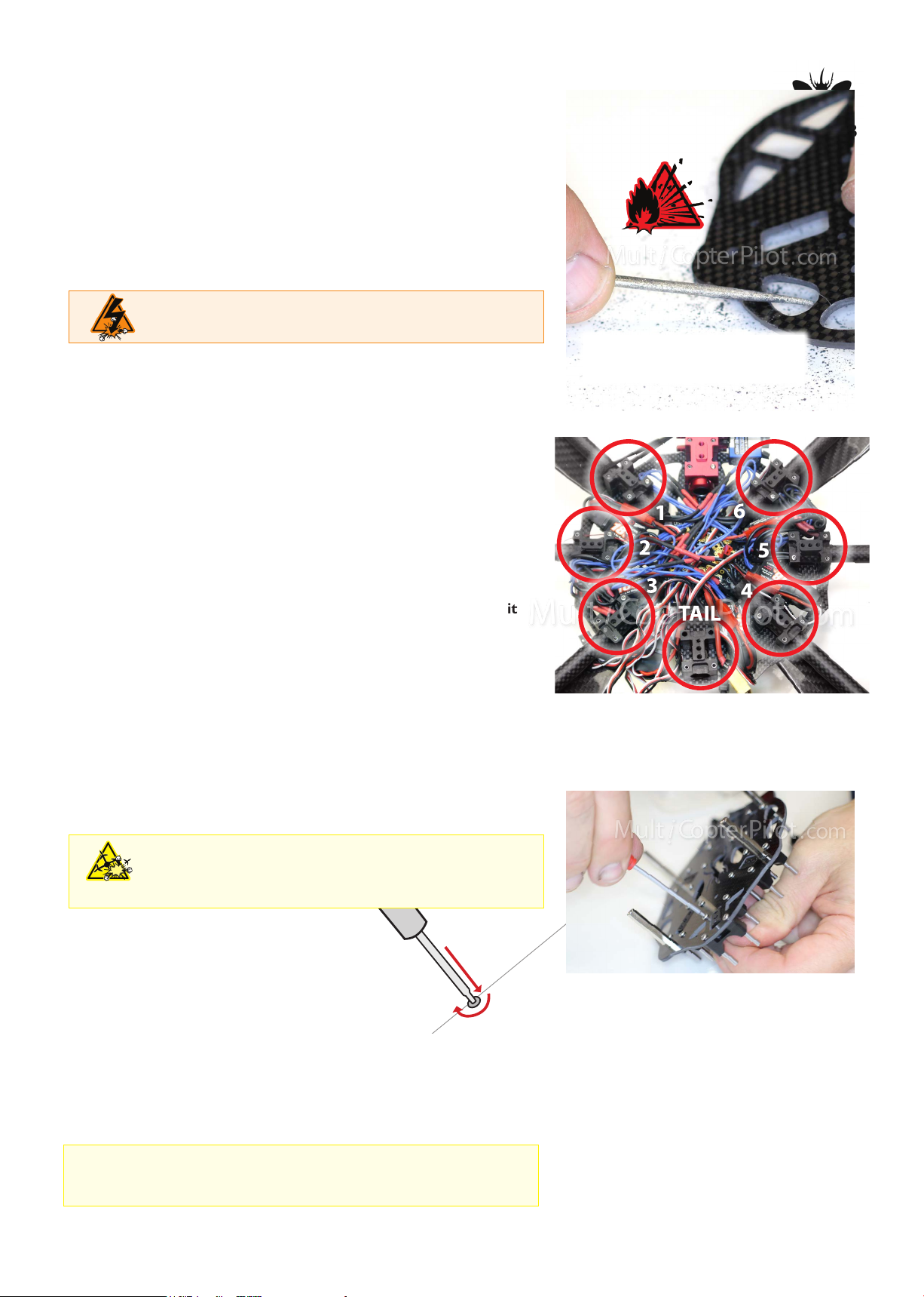
1. Sand rough edges with curved diamond le
Use diamond le to smooth curved edges of the frame, including
the beetle wings to prevent wires being cut by sharp edges.
Only light scraping is required. Do both sides and outside edges
Take care not to slip and scratch the plates.
carbon conducts electricty
Attaching Delrin®Boomholders
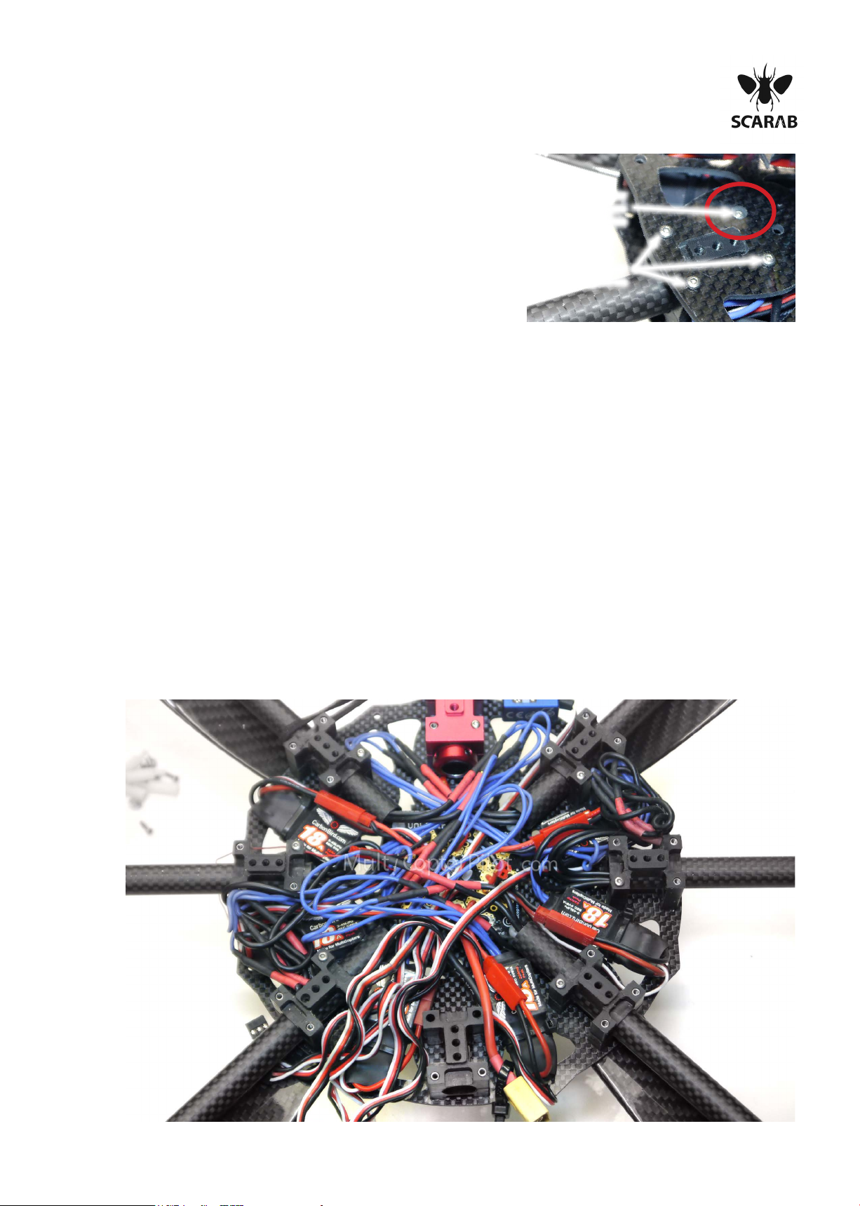
Insert M2*8 boomholder bolts into the Scarab™Airframe plate
from the bottom.
Place a small amount of loctite® onto bolt then screw on the
21mm Stainless Steel Shaft.
There are 6 booms on a Scarab™Vampire plus an additional
empty boom holder at the rear for tail attachment stability.
Ensure no loctite® is on the outside of the shaft as it
will lock boomholders.Wipe clean.
Repeat until all shafts are done on base.
NB:
NB:
removing all sharp edges
sharp edges can cut high current wires and
cause fires
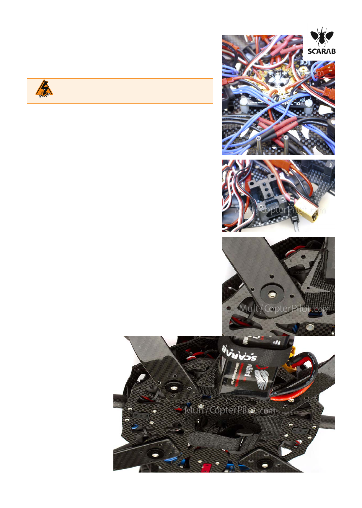
first push
then turn
Push Delrin® boomholder bases onto shafts.
Tighten the M2*8 boomholder bolts in base of Scarab™frame
now using 1/16th ProTool (hex key can alternatively be used).
Push Pro Tool in straight, otherwise bolt with strip.
Screw heads are stainless steel which is soft,
Pro Tool is hardened steel which is very hard.
If M2 heads are stripping out, this is a
technique fault.You are not pushing
the Pro Tool rmly in the rst instance.
A bolt with correct alignment require almost
zero force to turn - a cross-thread bolt will
be very stiff after one or two turns - STOP
Place boomholder tops on.
Screw M2*8 bolts into top of shafts finger tight to test / check
tolerances on all shafts and the threads on the M2 bolts
DO NOT SKIP THIS STEP, or you will regret it later when you
are pulling your whole frame apart to replace once shaft.
NB:


 user manual")


