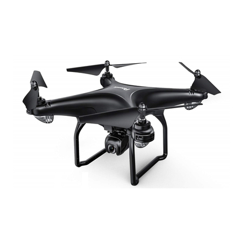
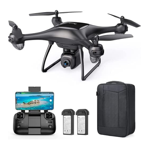
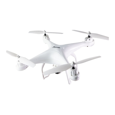
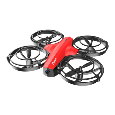
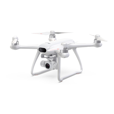
Potensic D60 User manual

Operation Guidance
D60
This product supports GPS positioning and is recommended for outdoor ight!
* This wi camera pinpoint is 5G, please conrm whether the phone is supported.

2
http://www.ipotensic.com
Catalog
Parts installation
6
Precautions before ying 7
Instruction for Drone and Transmitter 3
Pre-ight Operation Instruction 7
Functions Introduction 10
To know your APP 12
Spare Parts 13
Display the photos and video 13
Troubleshooting 14

3
Left Right
Front
Camera
Front
Rear
Rear
Drone Battery
Drone bottom
housing
Front LED
(Green)
Rear Led
(Red)
TF Card Slot
Propeller A
Propeller B
Propeller B
Propeller A
Drone upper
housing
Top cover
Instruction for Drone and Transmitter
Drone
Front LED
(Green)
Rear LED
(Red)
Main parameter
Drone size
Weight of drone
296x221x90.5mm
About 390g
About 300mins 1080P Camera pixels 1920x1080P
Flight time 14~18mins
Drone battery 7.4V 1800mAh
Pattern transmission 5.8GHz
Drone control mode 2.4GHz
Charging time of
drone battery
Flight distance
and radius
About 500m
(In the non-interference state)
Transmission
distance and radius
About 300m
(In the non-interference state)
http://www.ipotensic.com

4
No. Name No. Name No. Name
1Top cover
2Propeller A Concave lock cap
3
4
Propeller A (Clockwise)
5
Propeller B Flat lock cap
21
6
Silicone gasket
22
7
Propeller B (Counter Clockwise)
23
Camera presses
8
24
9
Drone upper housing
25
Clockwise Motor
Counter Clockwise Motor
Servo presses
26
GPS module
27
battery
28
Receiver board
Battery box
29
Optical Flow Board
Drone bottom housing
10
11
The steering gear
12
Camera hood
13 Photographic plate
Lens board
14
Electric palette
Camera shock absorber
15
2
3
4
5
6
7
8
9
10
11
12
13
14
15
16
17
18
5
1
4
6
24
8
25
26
22
15
15
22
17
3
2
5
5
15
27
16
18
20
23
21
17
18
28
19
19
29 19
Exploded View
Red LED motor board
16
17
18
19
Lampshade holder
20
Lampshade
Cushion
Receiving plate damping ring
Green LED motor board
http://www.ipotensic.com

5
Transmitter
Power switch
Left stick
(press down to follow)
One key taking o /
One key landing
One key returning home
Right stick
(press down to surround)
Photo/video Gimbal adjustment
Phone Holder
Trimmer Mode Button
Battery Cover
High/middle/ low speed
Gimbal Gear Adjustment Key: Press down the key to adjust the camera angle up and down.
Press the right rod to activate the 360° Function, which allows your drone to circle
around your desired point of interest.
Click H/L button to change your speed from High, Medium. or Low.
Photo: Click the camera button to take a photo. If you click it continuously, it will take several photos.
Video: Click the video button to record. Click again to nish recording.
Key Function
Left control rod: To control the drone up/down/Rotate left /Rotate right
Right control rod:
To control the drone forward/backward/Move left/Move right
Slide up the power switch to turn on the transmitter
Power switch:
Return Button:
One key taking o /
one key landing:
To begin ying, click the take o button to start the drone; To land press
the same button again.
Under GPS mode, Press the return button for a second & the drone will y
back. Press again, the drone will hover until you are ready to control it.
360° Function:
Follow Function:
Press the left rod to activate the follow function. Press again to stop.
High / middle /
low speed mode:
Trim Button:
Hold down the trim button while controlling the rod dials to slowly move
in the direction you want. Release the button to stop.
The installation method of battery
Open the battery cover on the back of the transmitter. According to the electrode
instructions of the battery box, put in 4 AA5 alkaline batteries (battery needs to be
purchased separately) .Close the battery cover(Picture 2).
http://www.ipotensic.com

6
Charging Instruction for Drone Battery
Drone Battery
Parts installation
Drone Battery Li-Po Battery Disposal & Recycling
Wasted Lithium-Polymer batteries must not be placed with household
trash. Please contact local environmental or waste agency or the
supplier of your model or your nearest Li-Po battery recycling center.
Power BankPhone Charger Computer Charging Car Charger
Picture 2
Picture 1
Battery Cover
4*1.5V
Alkaline battery
1.Make sure the electrodes are correct. 3.Do not mix dierent kinds of batteries.
2.Do not mix new with old batteries. 4.Do not charge the non rechargeable battery.
Notice:
Attaching your phone to the transmitter
Notice:Do not pinch the buttons on the mobile.
1. Pull up the phone holder clip on the transmitter (Picture 3). Pull down the little phone ledge
(Picture 4).
2. Place your phone between the clamp and ledge. It will tighten automatically (Picture 5/6)
1. First, Connect the drone battery with USB cable and then choose one of the following methods to
charge.
2. When the USB is charing the light will be red but after it is completely charged it will turn green
* For faster charging, it is recommended to use an adapter with 5V 2A output current (not
included) to charge the battery.
Picture 3 Picture 4 Picture 5 Picture 6
http://www.ipotensic.com

7
Propeller installation diagram
Diagram of battery handling
Press the button to
pull out the battery.
Sticker upwards
Picture 7
A Propeller:
B Propeller:
A Concave
lock cap
Bracket A
Propeller A
Silicone gasket B Flat lock cap
Bracket B
Propeller B
Silicone gasket
Precautions before ying
1. Make sure the transmitter and the battery of the drone are charged.
2. Before starting, please conrm that the left stick of the transmitter is in the middle position.
3. Please follow the correct steps to turn on the drone /transmitter. Before ight, turn on transmitter
and then the the drone. After ight, turn o the drone and transmitter. Turning ON/OFF incorrectly
may cause the drone to lose control.
4. Make sure to correctly install the battery, motor, etc.
5. Improper operation may cause drone crash, which may cause a motor defect, prevent you from
ying, and other issues. Please go to the local distributor to buy new parts for replacement so that
the drone will return to its best status.
When installing, insert the battery into the drone as per diagram (on picture 7) and the battery
sticker should be facing upward.
When removing, press the button on the battery and pull out the battery.
When installation,put the propeller and propeller lock cushion down on the motor shaft in order. After xing
the propeller, tighten the lock cap counterclockwise; When disassembled, turn the concave lock out clockwise
and take out the propeller upwards.
When installation,put the propeller and propeller lock cushion down on the motor shaft in order. After xing
the propeller, tighten the lock cap clockwise; When disassembled, turn the concave lock out counterclock-
wise and take out the propeller upwards.
Note: The propeller is marked "A" and "B", and the Concave lock cap must be corresponded to A propeller and
bracket A; And the Flat lock cap must be corresponded to B propeller and bracket B; If you get it wrong,
the drone can’t take o normally!
http://www.ipotensic.com
8
Insert the battery into the drone, then turn on the drone. The light on the drone will be solid for 2
seconds and then ash quickly. That means the frequency is successfully. the indicator light on the
left is ashing & there is no light on the right, it comes to level correction.
Compass calibration
Level Correction: Rotate the drone horizontally(Picture 8), the transmitter makes a beeping sound & the
left light of the drone turns bright, it means that it has successfully calibrated and comes to vertical
correction.
Vertical correction: Rotate the drone vertically (Picture 9), the right indicator lights will turn on. When
the transmitter makes the long beeping sound, the drones lights will begin its rotating ash, indicating
that it has nished calibration.
Picture 8
Level Correction
Picture 9
Vertical correction
Tips: It has to do the the compass calibration each time you start the drone, or it can't work
normally.
GPS Signal search
After successfully calibrating the frequency, the drone will automatically search for the GPS signal.
The blue light on the left of the transmitter is the GPS connection indicator, if it keeps long bright, that
means the connection to GPS. The drone can't work without GPS connection.
Calibration (This action is used when ying abnormally)
After making right frequency, please push the right stick
lever of the transmitter to the lower right angle of 45
degrees, please release it when the drone fuselage ash
quickly, it means you’ve nished compass calibration,
now the drone can y normally.
It must be placed on a at surface!
Flying steps
Syncing Frequencies
Turn on the power.
Push the left transmitter stick completely downwards.
Then the light will ash slowly. This means that the
transmitter is ready to sync.
http://www.ipotensic.com
9
Tips: When the drone is out of use, it can not be used to ne tune the light status, or be hit by a violent impact
(or abnormal fall). These all leads to the diculties in controlling, now you should make the right
frequency and calibrate it again. The drone must be placed on a at surface!
Unlocking/locking the motor
Unlock the motor:
Lock the motor:
Push the left and right stick inward to the 45
degree angle simultaneously.
The operation will stop the motor from running
immediately before the drone takes o.
One key taking o/one key landing
Tips: When you’re operating the “one key take o”, make sure that you’ve already unlocked the drone;
If not, you can't operate it.
After unlocking the drone, press the key for around one second, & the drone will y up to 1.2 meters
high. While ying, press the key for about one second, then the transmitter will make a beeping sound,
at this time the drone will start to land.
While landing, you shouldn't push up the left stick or it may stop the landing function.
Flying Control
Right
Stick
Adjust the stick to the right,
the drone will y right.
Adjust the stick to the left,
the drone will y left
Downward the right stick,
the drone will y backward.
Upwards the right stick ,
the drone will y forward.
http://www.ipotensic.com
10
While taking photos, press the photo key once to take one
photo. Press the key continuously, and you can take several
photos (While taking photos, clicking the key, will make the
transmitter beep).
While taking videos, press the key 1 second to start recording. The transmitter will beep indicating you
to operate it. If you want to stop it, you can press the button 1 second again.
Photo、Video
Press the key of gimbal adjustment,
the gimbal will move upward and downward, release the key
to stop it when it move to the angel you want.
Gimbal Adjustment
Function Introduction
Left
Stick
Adjust the stick to the left,
the drone will rotate left.
Adjust the stick to the right,
the drone will rotate right.
Upward the left stick,
the drone will y up.
Downward the left stick,
the drone will y down.
Left / Right Rotates Trimmer
When you take o, if the drone head rotates to the left, press the
trimmer button, and push left stick to right. Otherwise please
push it to the left.
Forward / Backward Trimmer
When taking o, if the drone tilts forward , press the trimmer button,
and push the right stick backward. Otherwise push it forward.
Left / Right Tilts Trimmer
When taking o, if the drone tilts to the left, press the trimmer button,
and push the right stick to the right. Otherwise push it to the left.
Trimmer
mode
http://www.ipotensic.com

11
One key returning
Notice: While returning, the control lever of the transmitter can not control the drone, wait for the
drone to go back to the take-o point. After indicating the direction of the drone during of
taking o, the control lever can navigate the drone.
Because the following function is based on the APP signal of
the mobile phone, before operating it, make sure that the
mobil phone is connected, or the function won't work.
While ying, press down on the key, the transmitter will
beep, indicating that the following function has been
activated.
Following Function
While ying, press the key for about one second, the transmitter will
beep”, then the drone will start returning to the take-o point. (While
returning, the transmitter will continuously beep).
* Press the key again to stop the return.
Press down on the right stick, the transmitter will beep, then it will enter the 360 ° function. The drone
will y to a default radius & wait for the user's directions. Adjust the speed and direction of the drone by
manipulating the right stick. There is a minimum radius of the default radius ,the drone ies only in the
sub range.
360 ° Function.
In the state of 360° function, the
left stick could only control the
height of the drone.
Turn left, the drone ies clockwise; If
you move the stick further upwards,
the ying speed will increase.
Pull downwards to enlarge the
circling radius.
Pull upwards to narrow the circling
radius.
Turn right, the drone ies
counterclockwise; If you move the
stick further upwards, the ying speed
will increase.
Press down
Constant Height Mode
Notice: If propeller or motor is damaged, the constant height function will not work. Due to
atmospheric pressure instability or unsuitable weather, the high altitude function will not
work either.
Intelligent hight control can calculate the suspended height,it has more stable control performance
to make the beginner operate it easily. So you do not need to have you hand on the stick to control
the drone, making it easer to focus on your aerial photography.
Press down
Intelligent ight control can calculate the suspended height.
The aim of xed point mode+constant height mode=spot hover , which gives the user more exibility
to take clear photos.
* This section is a GPS location xed-point. So before ying, make sure it is connected to GPS signal
or it will not work.
Fixed Point Mode
http://www.ipotensic.com
12
Stuck Protection
1. When the propeller is stuck and isn't spinning, the LED light will ick to start protection. Meanwhile, the
motor stops running.
2. Pull the left stick to the lowest position and then return it to it's normal position, at this time the LED
lights will shine brightly, unlocking the protection function, then the drone can take o normally.
Under below situations, the out of control protection might
be activated.
* The remote control is o.
* The drone ies out of distance.
* There is an obstacle between the remote control and the aircraft.
* The transmitter signal is interrupted.
Download and install APP: Potensic-GPS
This software is suitable for both IOS and Android systems,check the mobile phone app store to
download and install it.
1. The user of ISO mobile phone can surf App Store to
search Potensic-GPS to download.
2. The user of Android can surf Google Play to search
Potensic-GPS to download.
3. You can scan the QR code on the right or the QR code
on the color box directly to download and install it.
4. For detailed operation, please check the system “HELP”of APP.
Know your APP
Out of Control Protection
Out of Control Protection means the drone will automatically y back to the return points (the takeo
place after receiving the GPS signals) when the drone fails to connect to the drone transmitter (out of
control). It will reduce the drone losing or crashing accident.
The drone is not equipped with the obstacles avoidance function when returning. Please set the Return
altitude to avoid obstacles on the way back.
High / middle / low speed mode switch
Press down on the key, it will beep, this indicates the low speed mode ”L”; Press down again, it will beep
twice, for the middle speed mode “M”; Press down again ,it'll beep three times, for the high speed mode
“H”. 1. Low speed mode “Low”:
It’s suitable for the beginners to operate
in calm weather, with no breeze.
2. Middle speed mode “Middle”:
It’s suitable for those practicing (hobbyists)
to operate, with or without breeze.
3. High speed mode “High”:
It’s suitable for the professionals in most
outdoor wind conditions.
High / Middle /
Low speed key
Low Battery Alarm
When the battery of the remote is almost out of power, it will continually beep to alert you, that you
should land the drone as soon as possible, to replace the battery.
While ying, if the battery of the drone is exhausted, it will beep to alarm you, the drone's indicator
lights will ash. After alarming you, the drone automatically return to your take-o point.
Notice: After low-battery alarm, the drone will return home. Meanwhile, its controllable range will be reached
to the 20 meter radius.
Out of Range Alarm
While ying, when the drone goes out of distance, the transmitter will beep to alarm you to y back the
drone within range immediately.
http://www.ipotensic.com
13
Picture 10
1. Insert the TF card to the slot in accordance with Picture 10. (*TF card
is not included)
2. The photos will be saved in your mobile phone & on the TF card,
while videos can only be saved on the TF card. But you can
download the video to your mobile phone or view it on the phone
when it's connected to the drone's WiFi and the TF card is in the
drone.
Tip: Please play the video or photo after coping all aerial photography data to computer and
make sure the play software can support AVI format.
To take photo and record video
Tip: Click on the video icon to save a video when ending recording, or the video cannot be saved.
3. Power o the drone after you nish taking photos. Take out the TF card and insert it into a card reader.
Connect the card reader with a computer USB port. Then view the aerial photography data from “my
computer” - ” mobile disk” .
Components (Sold separately)
Drone upper housing Drone bottom housing Top cover Propeller A
Propeller A
Concave lock cap Flat lock cap Lampshade holder
Propeller B
Magnetic plate GPS module Flight Battery USB Charger
Cushion Camera hood Battery holder
Lampshade
http://www.ipotensic.com
14
TF Card Card Reader Hex Wrench Screw Driver Transmitter
Our company's products are improving all the time, design and specications are subject to change
without notice.
All the information in this manual has been carefully checked to ensure accuracy, if any printing errors,
our company reserve the nal interpretation right.
http://www.ipotensic.com
Important Notice
Troubleshooting
The
controller
indicator
light is o.
The drone
is under-
powered
or can not
y.
The drone
could not
hover and
tilts to one
side.
1
3
4
Problem Problem Cause Solution
No.
1. Low battery. 1. Replace the controller battery.
2. The batteries are incorrectly
positioned.
2. Install the batteries following the
polarity indicators.
3. Poor Contact. 3. Clean the dirt between the
battery and the battery contacts.
1. Indicator light is o. 1. The same as above.
2. There is an interfering
signal nearby.
2. Restart the drone and power on
the controller.
3. Mis-operation. 3. Operate the drone step by step in
accordance with the user manual.
4. The electronic component
is damaged for ercely crash.
4. To buy spare parts from local
seller and replace damaged parts.
1. The propeller is seriously deformed. 1. Replace the propeller.
2. Low battery. 2. Charge the drone battery.
3. Incorrect installation of propeller. 3. Install the propeller in accordance
with the user manual.
2. The propeller is seriously deformed. 2. Replace the propeller.
3. The motor holder is deformed after
violent crash. 3. Replace the motor holder parts.
1. Improper Calibration.
1. Please refer to the Calibration Instruction.
4. The gyroscope did not reset after a
serious crash.
4. Put the drone on the at ground
for about 10 minutes or restart the
drone to calibrate again.
Failed to
pair the
drone with
the
controller.
2
5. Motor is damaged. 5. Replace the motor.
6. No proofreading compass. 6. Re proofreading the compass.
The drone
indicator
light is o.
Could not
see the
picture.
5
6
1. Low battery. 1. Recharge the drone battery.
2. The battery is expired or over
discharge protection.
2. Buy a new battery from local seller to
replace the battery or charge the battery
in accordance with the use manual.
3. Poor contact. 3. Connect and disconnect the battery.
1. There is an interfering signal
nearby.
1. Practice and read the cellphonecon-
trolling instruction carefully.
2. Camera is damaged. 2. Replace Camera.

15
Hard to control
by cellphone.
7
Not experienced enough. Practice and read the cellphone
controlling instruction carefully.
Can’t position
hold.
9
Whether the GPS has
connected or not.
Search again to connect the GPS
signal.
Searched but
could
not nd the
GPS signal
10
1. GPS module is damaged.
2. Poor connection
1. Please replace a new one.
2. Please check to see if the GPS module
is connected normally.
Can’t
altitude
hold.
8
1. The propeller is seriously
deformed.
1. Replace propeller.
2. The motor is damaged. 2. Replace the motor.
3. Atmospheric pressure
is not stable.
3. Refer to “Altitude Hold
Mode”instruction.
FCC Note
This equipment has been tested and found to comply with the limits for a Class B digital device, pursuant
to Part 15 of the FCC Rules. These limits are designed to provide reasonable protection against harmful
interference in a residential installation. This equipment generates uses and can radiate radio frequency
energy and, if not installed and used in accordance with the instructions, may cause harmful interference
to radio communications. However, there is no guarantee that interference will not occur in a particular
installation. If this equipment does cause harmful interference to radio or television reception, which can
be determined by turning the equipment o and on, the user is encouraged to try to correct the
interference by one or more of the following measures:
●Reorient or relocate the receiving a ntenna.
●Increase the separation between the equipment and receiver.
●Connect the equipment into an outlet on a circuit dierent from that to which
the receiver is connected.
FCC Notice:
FCC Radiation Exposure Statement
WARNING: Changes or modications not expressly approved by the party responsible for
compliance could void the user's authority to operate the equipment.
The equipment may generate or use radio frequency energy. Changes or modications to this
equipment may cause harmful interference unless the modications are expressly approved in the
instruction manual. Modications not authorized by the manufacturer may void user’s authority to
operate this device.
This device complies with Part 15 of the FCC Rules. Operation is subject to the following two
conditions:
(1) This device may not cause harmful interference.
(2) This device must accept any interference received, including interference that may cause undesired
operation.
The device has been evaluated to meet general RF exposure requirement.
The device can be used in portable exposure condition with out restriction.
MADE IN CHINA
www.ipotensic.com
http://www.ipotensic.com
16
Table of contents
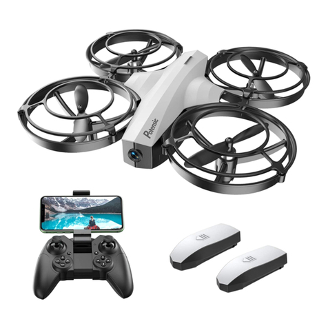
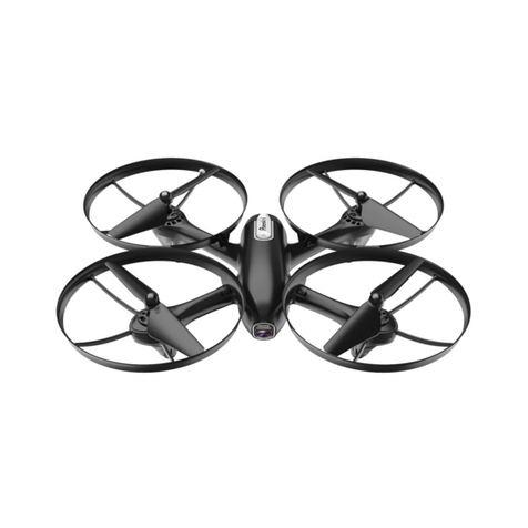
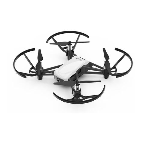
Other Potensic Drone manuals

Potensic
Potensic Wisp User manual

Potensic
Potensic P7 User manual

Potensic
Potensic A30 User manual

Potensic
Potensic Dreamer Mini User manual

Potensic
Potensic F186 DH User manual

Potensic
Potensic D58 User manual

Potensic
Potensic Dreamer Pro User manual

Potensic
Potensic Dreamer Mini User manual

Potensic
Potensic U47 User manual

Potensic
Potensic D88 User manual