Schäfter+Kirchhoff 60FC-T Series User manual

Fiber Collimators Series 60FC-T
Adjustment_60FC-T 18.12.2020 © Schäfter+Kirchhoff GmbH
Schäfter+Kirchhoff GmbH Kieler Str. 212 22525 Hamburg, Germany +49 40 85 39 97-0 [email protected] www.sukhamburg.com
1
Fiber Collimators Series 60FC-T
This document provides assistance in installing the fiber collimators series 60FC-T. It describes how a fiber
cable is attached and how the collimation setting is adjusted.
Before You Start
The fiber collimator is shipped with a protection cap for the fiber receptacle and with a front cap.
Please remove all the protection caps first and do not use them as beam
dumps (risk of photo contamination).
Notice:
There is a two-part protection cap on the receptacle. Please perform the following steps in order to remove
this cap:
Figure 1:
First, remove the threaded cap from
the fiber receptacle of the fiber
collimator.
Figure 2:
Then, slightly loosen the small pin
screw. Use the screwdriver 9D-12.
Make sure to not loosen it too far, as it
is small and easily lost.
Figure 3:
Now, pull out the plug.

Fiber Collimators Series 60FC-T
Adjustment_60FC-T 18.12.2020 © Schäfter+Kirchhoff GmbH
Schäfter+Kirchhoff GmbH Kieler Str. 212 22525 Hamburg, Germany +49 40 85 39 97-0 [email protected] www.sukhamburg.com
2
Now, make sure that the connector of the fiber you want to attach matches the receptacle type of the fiber
collimator:
• Use fibers with FC-APC (8°-polish) connectors for fiber collimators with an inclined coupling axis
(60FC-T-4).
• Use fibers with FC-PC (0°-polish) connectors for fiber collimators with a coaxial axis
(60FC-T-0).
The fiber collimators are compatible to all fiber connectors type FC, including fiber connectors with end caps.
• Do not touch either the optical surface of the lens or the fiber end-face.
• If the coupler is not in use, reattach both rear and front protection caps.
Notice:
Refer to the laser instruction manual for all instructions regarding laser
safety!
• Do not stare directly into the laser beam (which can cause permanent
damage to the eyes).
• Do not stare at the reflected beam from reflective objects.
• Do not point the laser beam to other individuals.
Caution!
1. Attaching a Fiber Cable to the Fiber Collimators
For attaching a fiber cable to the fiber collimator perform the following steps:
Figure 4:
To prevent damage to the sensitive
fiber end-face, always insert the fiber
connector`s ferrule Aat an angle, with
the connector key Bproperly aligned
to the receptacle notch C.
Figure 5:
When the ferrule tip is safely located
in the inner cylinder of the receptacle,
align the connector to the receptac-
le axis and carefully introduce the
connector into the fiber collimator.
A
B
C

Fiber Collimators Series 60FC-T
Adjustment_60FC-T 18.12.2020 © Schäfter+Kirchhoff GmbH
Schäfter+Kirchhoff GmbH Kieler Str. 212 22525 Hamburg, Germany +49 40 85 39 97-0 [email protected] www.sukhamburg.com
3
Figure 6:
Then, orient the connector key in a
way that it is pressed gently onto
the right-hand side of the receptacle
notch.
Figure 7:
Gently screw on the connector cap
nut onto the receptacle until it is
finger-tight.
Figure 8:
Finally, gently tighten the fiber grub
screw to reduce the free play of the
ferrule in the receptacle.
The free play in between the connector ferrule and receptacle is only a few microns, but necessary for
inserting the ferrule without force.
The tightened grub screw and the right-hand orientation rule for the connector, ensure a high reproducibility
in mode field position and angle, which is especially important for attaching and reattaching polarization-
maintaining fibers reproducibly.

Fiber Collimators Series 60FC-T
Adjustment_60FC-T 18.12.2020 © Schäfter+Kirchhoff GmbH
Schäfter+Kirchhoff GmbH Kieler Str. 212 22525 Hamburg, Germany +49 40 85 39 97-0 [email protected] www.sukhamburg.com
4
2. Adjusting the Collimation Setting
Collimation adjustment (adjustment of the collimating lens in z-direction) is a demanding task and should be
performed preferably using a collimating telescope.
The fiber collimator is shipped pre-adjusted for the given wavelength and,
often, it is not necessary for the customer to readjust the lens position. This
is why you can skip this step in most cases.
Notice:
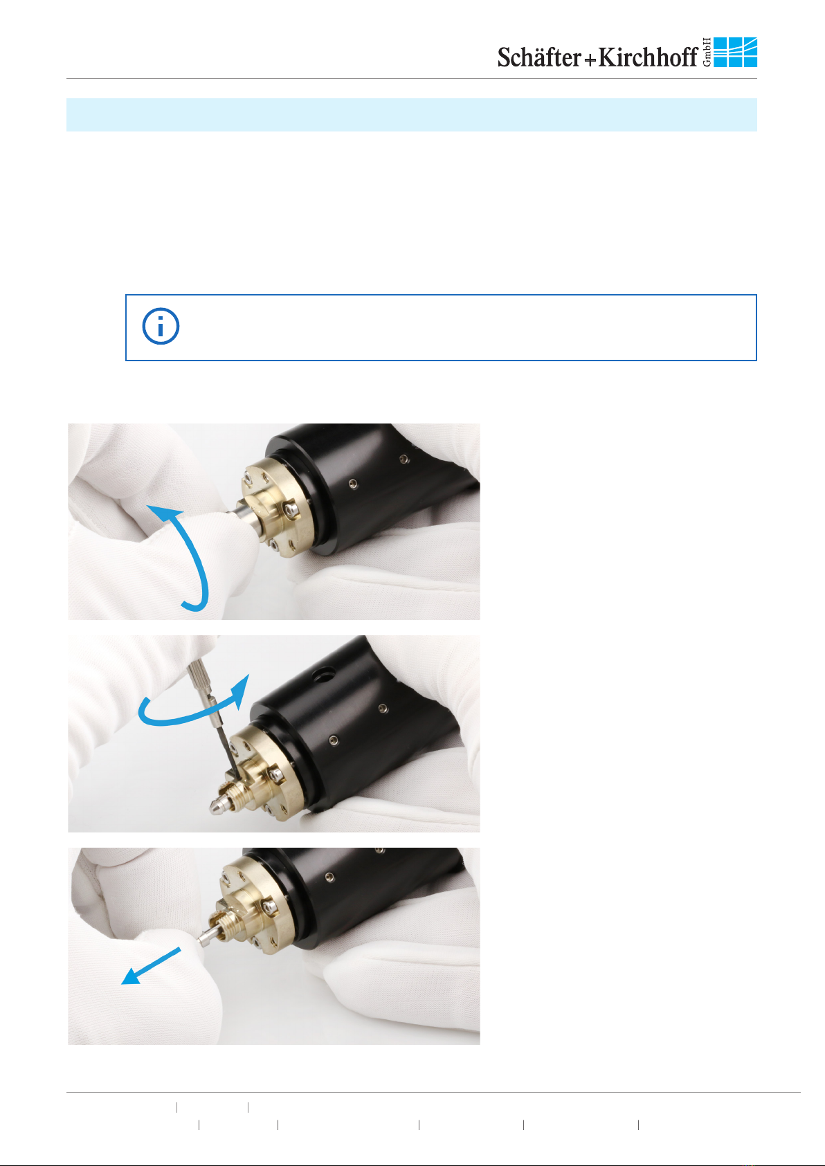
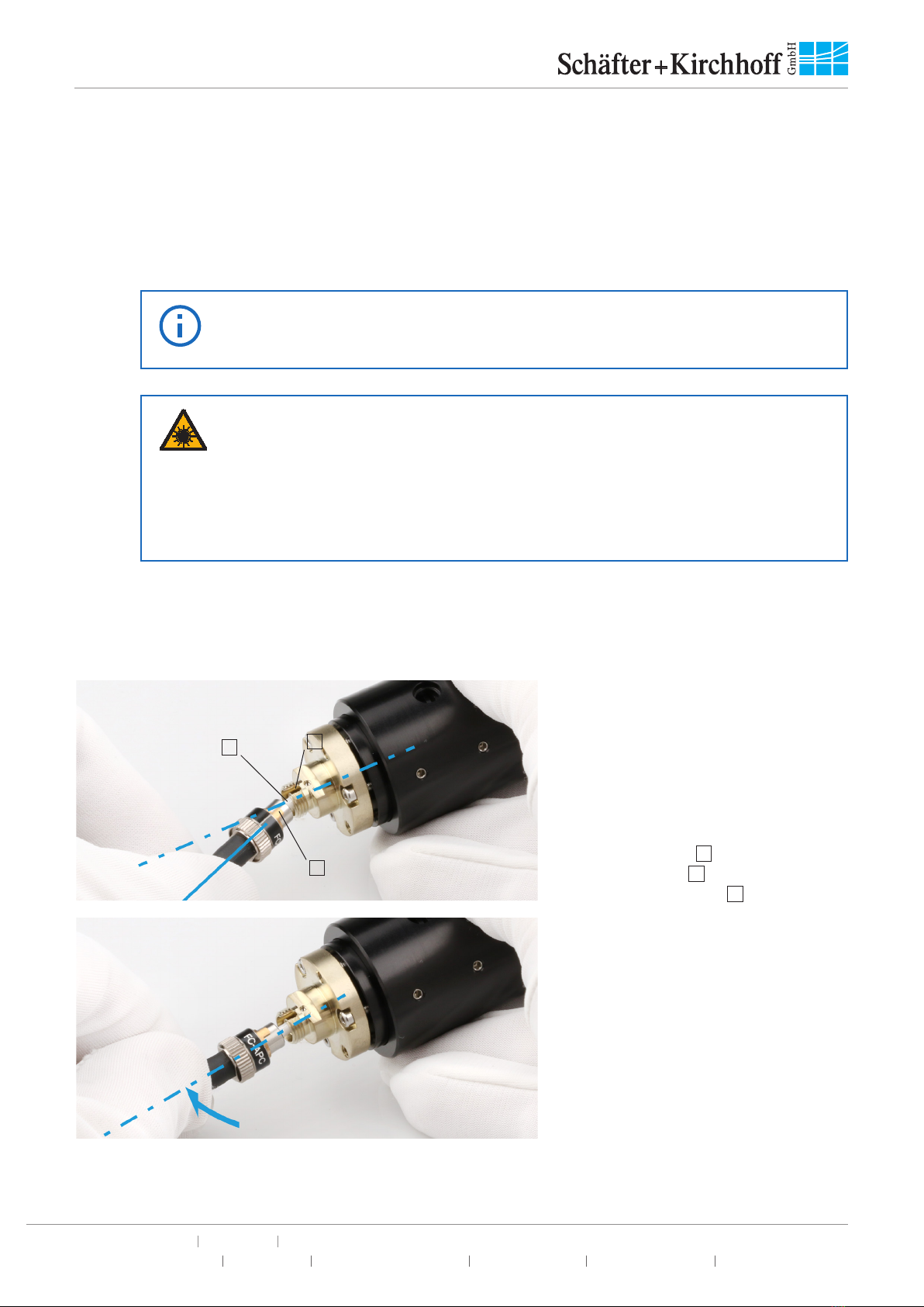
To check the collimation setting of the fiber collimator, couple a radiation source of appropriate wavelength into
the fiber connected to the fiber collimator.
Refer to the laser instruction manual for all instructions regarding laser
safety!
• Do not stare directly into the laser beam (which can cause permanent
damage to the eyes).
• Do not stare at the reflected beam from reflective objects.
• Do not point the laser beam to other individuals.
Caution!
There are two options for rating the collimation setting:
• For fiber collimators with a focal length f‘ >30 mm it is best to use a shearing interferometer.
• For fiber collimators with a focal length f‘ ≤30 mm you can use the following procedure as an
alternative:
Direct the beam to a target about half a Rayleigh length zRaway:
zRπ∙∅2
beam
=
2 λ∙8
Here λ is the optical wavelength and Øbeam the collimated beam diameter (1/e2level).
When correctly collimated, the laser spot diameter on a target about zR/2 away must have
approximately the same diameter such as the beam directly behind the laser beam coupler.
Additionally, make sure that there is no focused spot between the laser beam coupler and the
target at zR/2.
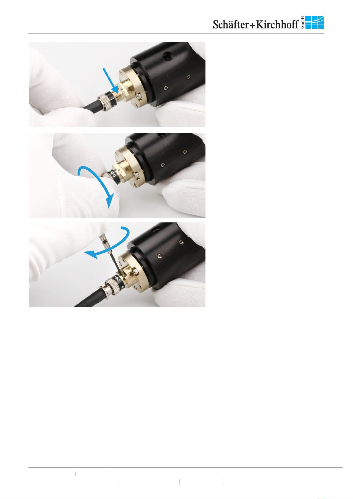
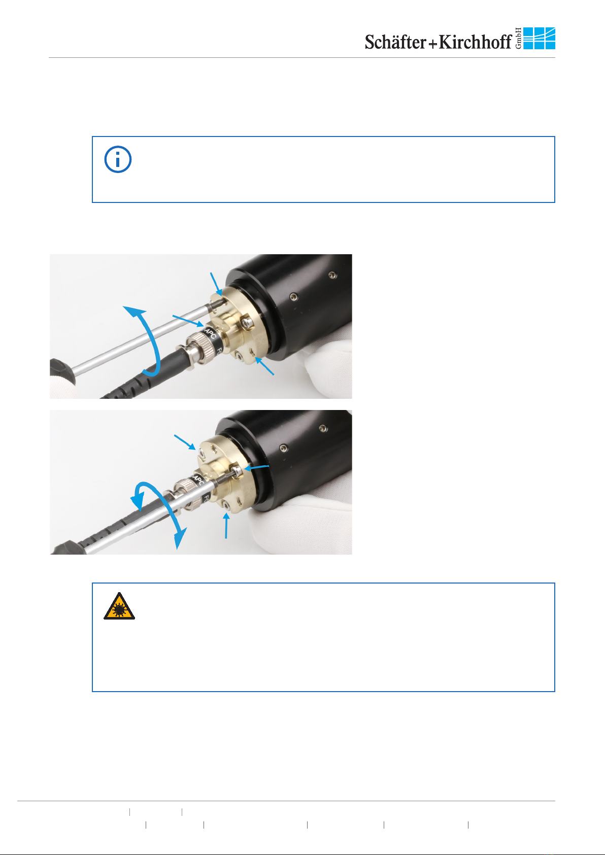
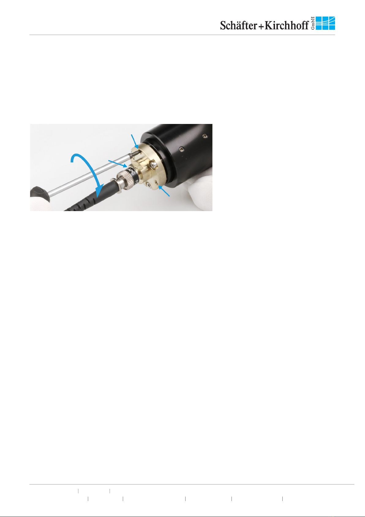
The lens position is adjusted by means of an eccentric key type 55EX-5.
For adjusting the lens position perform the following steps:
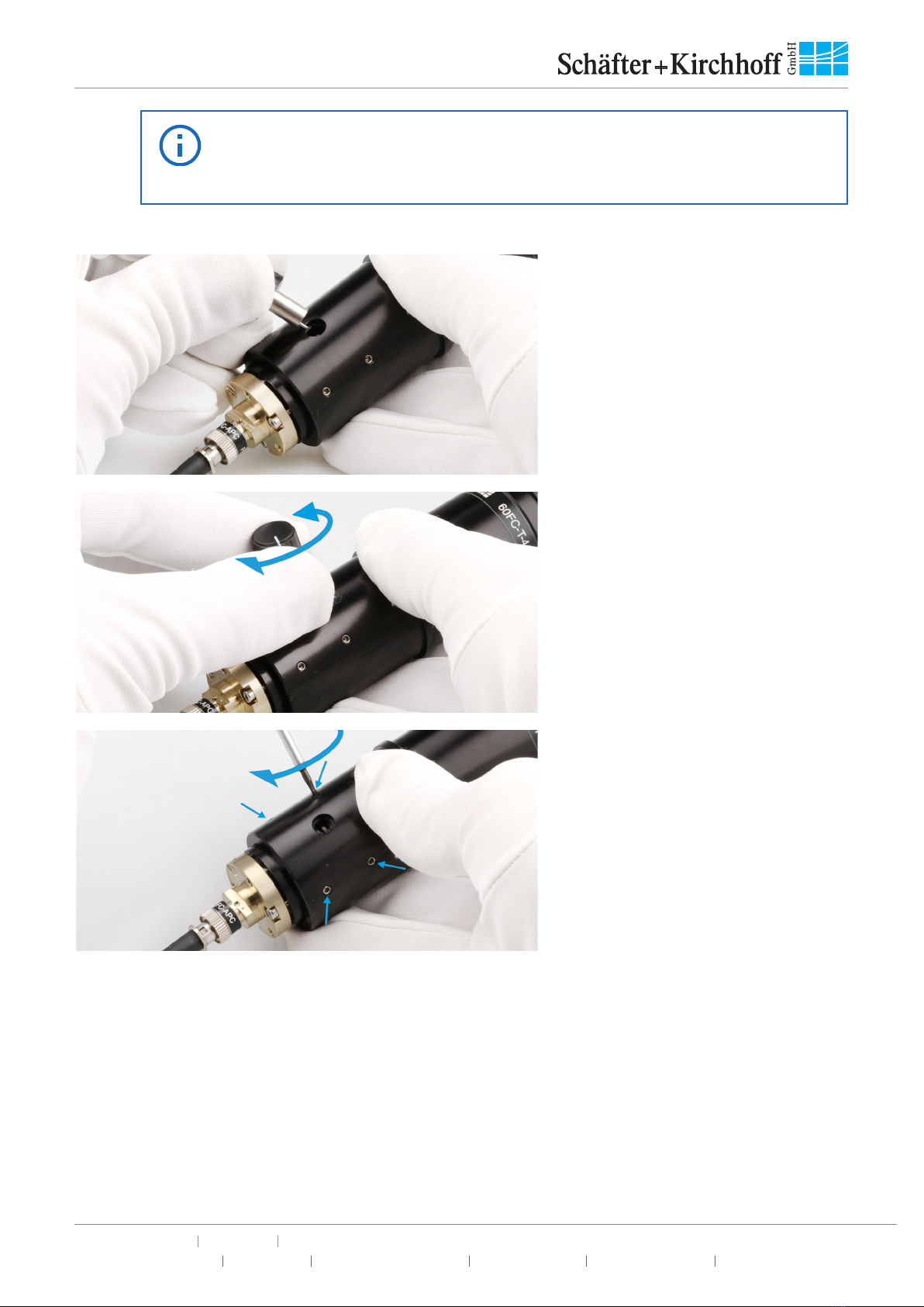
Figure 9:
Loosen the clamp screws fixing the
lens position by means of a screwdriver
type 50HD-15.

Fiber Collimators Series 60FC-T
Adjustment_60FC-T 18.12.2020 © Schäfter+Kirchhoff GmbH
Schäfter+Kirchhoff GmbH Kieler Str. 212 22525 Hamburg, Germany +49 40 85 39 97-0 [email protected] www.sukhamburg.com
5
The number of clamp screws (two or four) depends on the individual type of
fiber collimator. For the exact position of these clamp screws please refer to
the technical drawing of the individual fiber collimator, respectively.
Notice:
Figure 10:
Insert the eccentric key type 55EX-5
into the large hole.
Figure 11:
Now, adjust the focus setting by
rotating the eccentric key. Use the
shearing interferometer or adjust the
collimation by minimizing the size of the
laser spot on the target about half the
Rayleigh length zRaway.
Figure 12:
Finally, fix the clamp screws in order to
lock the collimation setting.

Fiber Collimators Series 60FC-T
Adjustment_60FC-T 18.12.2020 © Schäfter+Kirchhoff GmbH
Schäfter+Kirchhoff GmbH Kieler Str. 212 22525 Hamburg, Germany +49 40 85 39 97-0 [email protected] www.sukhamburg.com
6
3. Tilt Adjustment
The fiber collimators of series 60FC-T have an integrated tilt alignment mechanism.
With this mechanism you can adjust the optical axis to the mechanical axis of the fiber collimator.
This mechanism is not suitable for adjusting the beam pointing of the fiber
collimator in your setup. If you want to adjust the beam pointing, use an
external alignment device such as an adjustable mirror mount.
Notice:
For adjusting the optical axis with respect to the mechanical axis perform the following steps:
Figure 13:
Loosen the three locking screws (grub
screws) by 2 - 3 turns. Use the hex
screwdriver 50HD-15.
Figure 14:
Now, adjust the optical axis by
means of the three adjustment screws
(hex with head). Again, use the hex
screwdriver 50HD-15.
Refer to the laser instruction manual for all instructions regarding laser
safety!
• Do not stare directly into the laser beam (which can cause permanent
damage to the eyes).
• Do not stare at the reflected beam from reflective objects.
• Do not point the laser beam to other individuals.
Caution!
There are two options for rating the alignment:
• Observe the collimated radiation on a screen placed in a large distance from the fiber collimator.
The distance that is most sensitive for this method again is about half the Rayleigh range zR, see
Chapter 2.
Rotate the fiber collimator along its mechanical axis.

Fiber Collimators Series 60FC-T
Adjustment_60FC-T 18.12.2020 © Schäfter+Kirchhoff GmbH
Schäfter+Kirchhoff GmbH Kieler Str. 212 22525 Hamburg, Germany +49 40 85 39 97-0 [email protected] www.sukhamburg.com
7
The alignment of the optical axis is best when the position of the spot on the screen does not alter.
• A second option can be used only when the fiber collimator has a clear aperture that is small
with respect to the fiber NA. Then the collimated beam is truncated by the aperture of the fiber
collimator at a lower level of the Gaussian intensity distribution:
Observe the collimated radiation on a screen placed in front of the fiber collimator (for laser safety
or in case of invisible radiation use a camera for this purpose).
The alignment of the optical axis is best when the beam truncation seen on the screen is axially
symmetric.
Figure 15:
Finally, lock the three grub screws.
Use a torque of max. 40 Ncm.

Fiber Collimators Series 60FC-T
Adjustment_60FC-T 18.12.2020 © Schäfter+Kirchhoff GmbH
Schäfter+Kirchhoff GmbH Kieler Str. 212 22525 Hamburg, Germany +49 40 85 39 97-0 [email protected] www.sukhamburg.com
8
4. Adjustment Tools
For assembling and adjusting the fiber collimators series 60FC-T you need the following tools:
Figure 16:
Screw driver type 9D-12, hex key
50HD-15, and eccentric key type 55EX-5.
Copyright
• © Unless expressly authorized, forwarding and duplicating of the document and the utilization
and communication of its contents are not permitted. Violations will entail an obligation to pay
compensation.
• All rights in the event of granting of patents or registration of a utility model.
• Schäfter+Kirchhoff GmbH and the Schäfter+Kirchhoff logo are registered trademarks.
• The specifications are subject to change; the manual is not covered by an update service.
• The system shown on the photos and drawings of this manual may differ in detail from the
system delivered.
Date of issue: 18.12.2020
Schäfter+Kirchhoff GmbH
Kieler Straße 212, 22525 Hamburg, Germany
Phone: +49 40 85 39 97-0
Fax: +49 40 85 39 97-79
Email: info@sukhamburg.de
Web: http://www.sukhamburg.com
This manual suits for next models
1
Table of contents
Other Schäfter+Kirchhoff Industrial Equipment manuals

Schäfter+Kirchhoff
Schäfter+Kirchhoff 60FC-A19.5 Series User manual

Schäfter+Kirchhoff
Schäfter+Kirchhoff 60FC Series User manual

Schäfter+Kirchhoff
Schäfter+Kirchhoff 60SMS Series User manual

Schäfter+Kirchhoff
Schäfter+Kirchhoff 60FC-LSA Series User manual

Schäfter+Kirchhoff
Schäfter+Kirchhoff 60FC-A19.5 Series User manual

Schäfter+Kirchhoff
Schäfter+Kirchhoff 60FC-K Series User manual

Schäfter+Kirchhoff
Schäfter+Kirchhoff 60FC-SF Series User manual

Schäfter+Kirchhoff
Schäfter+Kirchhoff 60FC-F Series User manual

Schäfter+Kirchhoff
Schäfter+Kirchhoff 60FC-Q Series User manual