cascade corporation D Series Operating manual

Cascade is a Registered Trademark of Cascade Corporation
cascade
corporation
ERVICE MANUAL SUPPLEMENT
S
Tipping Carton Clamps
D-Series
Manual Number 6905873
NOTE: This manual covers tipping components only. Refer to D-Series
Carton Clamp Service Manual, part number 228156, for periodic
maintenance, troubleshooting and service to carton clamp components
including arms, carton clamp cylinders and frame.

CONTENTS
i6905873
Page
INTRODUCTION, Section 1
Introduction 1
Special Definitions 1
PERIODIC MAINTENANCE, Section 2
Daily Inspection 2
1000-Hour Maintenance 2
TROUBLESHOOTING, Section 3
General Procedures 3
Truck System Requirements 3
Tools Required 3
Troubleshooting Chart 4
Plumbing 5
Hosing Diagram – Non-Sideshifting 5
Hydraulic Schematic – Non-Sideshifting 6
Hosing Diagram – Cartridge Type Solenoid/Radio Frequenct (RF) Control 7
Hydraulic Schematic – Cartridge Type Solenoid/Radio Frequenct (RF) Control 8
Hosing Diagram – Solenoid 9
Hydraulic Schematic – Solenoid 10
Tipping Function 11
Supply Circuit Test 11
Tipping Circuit Test 11
Electrical Circuit 12
SERVICE, Section 4
Attachment Removal 13
Arms 14
Clamp Cylinders 14
Clamp Valve 14
Base Unit 14
Back Mounting Frame 15
Removal and Installation 15
Bushing Service 16
Tipping Cylinder 17
Removal and Installation 17
Counterbalance Valve Cartridge Service 18
Cylinder Bushing Service 19
Cylinder Disassembly 20
Cylinder Inspection 20
Cylinder Reassembly 21
Valves 22
Counterbalance Valve Service 22
Cartridge Type Solenoid Valve or Radio Frequency Valve 23
Solenoid Valve Coil Service 25
SPECIFICATIONS, Section 5
Hydraulics 26
Auxiliary Valve Functions 26
Truck Carriage 27
Torque Values 28

INTRODUCTION
6905873 1
CATALOG NO.
15D-CCU-2A-12345
SERIAL NO.
PTL012345678
+
7
@
123
+
A2-Z
Cascade Corporation • www.cascorp.com • Icons & Patents: www.cascorp.com/support 6095754
15D-CCU-2A-12345
PTL012345678
CC0163.eps
1.1 Introduction
This manual provides the Periodic Maintenance, Troubleshooting,
Service and Specifications for Cascade D-Series Tipping Carton
Clamps.
In any communication about the attachment, refer to the product
catalog and serial numbers stamped on the nameplate, as shown.
If the nameplate is missing, the numbers can be found stamped
on the frame where the plate was mounted.
IMPORTANT: Cascade D-Series Tipping Carton Clamps are
custom built and size of connecting supply fittings on the
attachment will vary. Consult Cascade if fitting size and type can
not be determined.
NOTE: Specifications are shown in both US and (Metric) units.
All fasteners have a torque value range of ±10% of stated value.
1. 2 Special Definitions
The statements shown appear throughout this manual
where special emphasis is required. Read all WARNINGS
and CAUTIONS before proceeding with any work.
Statements labeled IMPORTANT and NOTE are provided
as additional information of special significance or to make
your job easier.
WARNING - A statement preceded by
WARNING is information that should be
acted upon to prevent bodily injury. A
WARNING is always inside a ruled box.
CAUTION - A statement preceded by CAUTION is
information that should be acted upon to prevent
machine damage.
IMPORTANT - A statement preceded by IMPORTANT is
information that possesses special significance.
NOTE - A statement preceded by NOTE is information that
is handy to know and may make your job easier.
Nameplate

6905873
PERIODIC MAINTENANCE
2
CC0164.eps
2.1 Daily Inspection
Prior to each shift of truck operation, complete the following
procedures:
• Check for loose or missing bolts, worn or damaged
hoses and hydraulic leaks.
• Check decals and nameplate for legibility.
2.2 1000-Hour Maintenance
After each 1000 hours of truck operation, in addition to the
daily inspection, perform the following procedures:
• Check lower mounting hooks for engagement. Hooks
should be tight against lower carriage. If adjustment is
necessary, refer to Section 4.1, Step 3.
• Tighten lower hook capscrews to 120 ft.-lbs. (165 Nm).
• Inspect all tipping pivot bushings and pins for wear.
Replace, as needed.
• Tighten tipping eye pin or retainers capscrews to:
Retainer Capscrews – 14 ft.-lbs. (19 Nm)
Eye Pin Capscrew – 28 ft.-lbs. (38 Nm)
WARNING: After completing any service
procedure, always test the attachment
through five complete cycles. First test
the attachment empty, then test with a load
to make sure the attachment operates
correctly before returning to the job.
OR
OR
Side View
IMPORTANT: This section covers periodic maintenance
for tipping components only. In addition to the periodic
maintenance below, perform the periodic maintenance
found in D-Series Carton Clamp Service Manual, Part No.
228156.
CC0166.eps
Eye Pin
Capscrew
Eye Pin
Capscrew
Tipping Cylinders
Lower Mounting Hooks
Back (Driver's) View
Retainer
Capscrews
Retainer
Capscrews

6905873
TROUBLESHOOTING
3
3.1 General Procedures
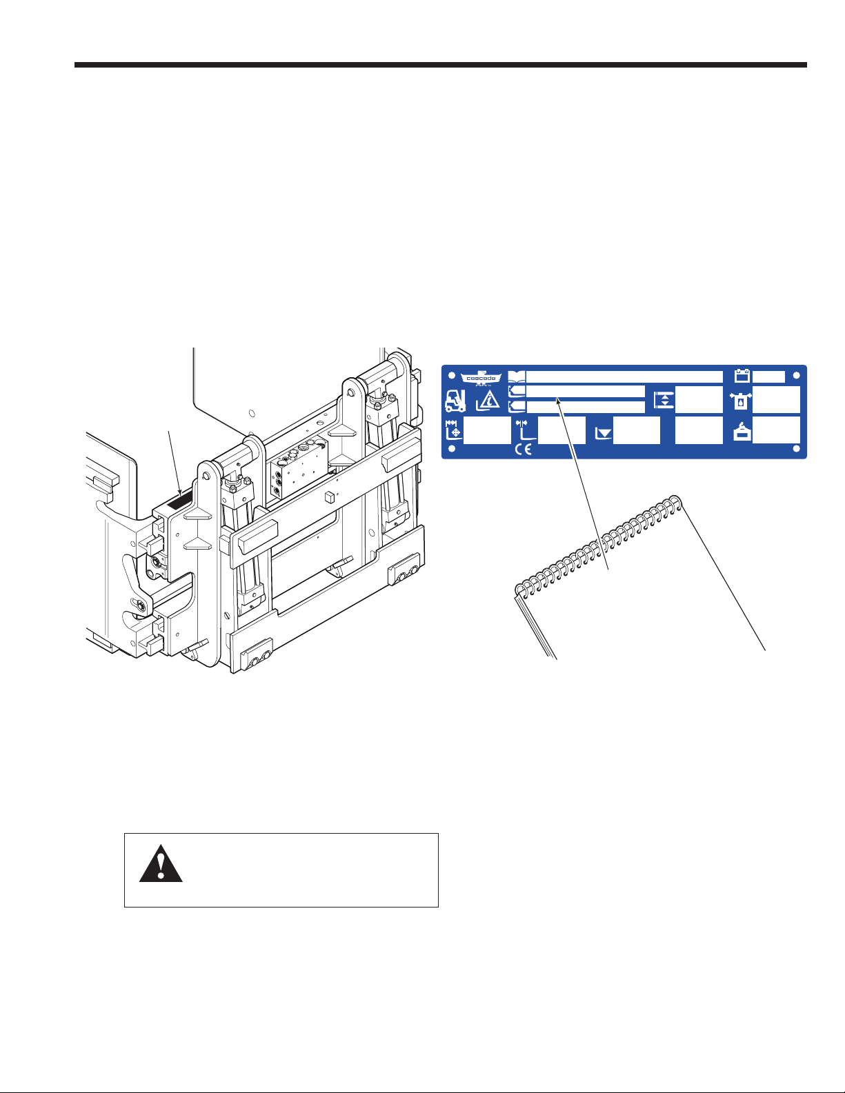
IMPORTANT: Troubleshooting the SIDESHIFT or CLAMP
circuits can be found in D-Series Carton Clamp Service
Manual 228156.
3.1-1 Truck System Requirements
• Truck hydraulic pressure should be within the range
shown in Specifications, Section 5.1. Pressure to the
attachment must not exceed 2300 psi (160 bar).
• Hydraulic flow should be within the volume range as
shown in Specifications, Section 5.1.
• Hydraulic fluid supplied to the attachment must meet the
requirements as shown in Specifications, Section 5.1.
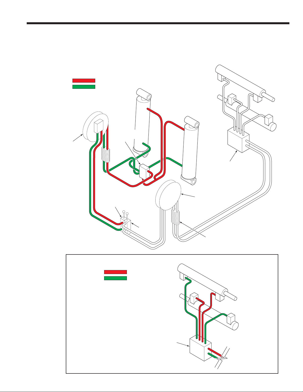
3.1-2 Tools Required
In addition to a normal selection of hand tools, the following
will be required:
• Inline Flow Meter Kit:
20 GPM (75 L/min.) - Cascade Part No. 671477.
• Pressure Gauge Kit:
5000 psi (345 bar) - Cascade Part No. 671212. Two kits
are required.
OR
Wireless Pressure Monitor Kit:
Pressure transducers monitor the hydraulic pressure
and wirelessly transmit the data to the receiver display.
• Assorted fittings and hoses to adapt the gauge and flow
meter to the components being tested.
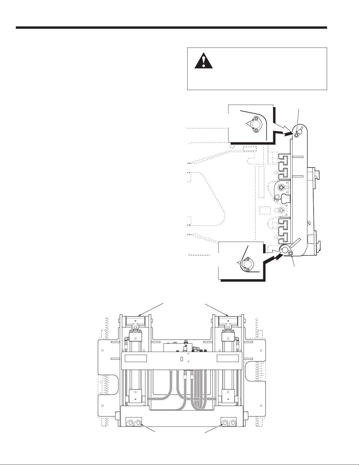
WARNING: Before servicing any
hydraulic component, relieve pressure
in the system. Turn the truck off and
move the truck auxiliary control valves
several times in both directions.
After completing any service procedure, test the
attachment through several cycles. First test
the attachment empty to bleed any air trapped
in the system to the truck tank. Then test the
attachment with a load to be sure it operates
correctly before returning to the job.
Stay clear of the load while testing. Do not raise
the load more than 4 in. (10 cm) off the floor while
testing.
Pressure
Gauge ▲
No. 6 and No. 8
JIC Swivel Tee
No. 4-6 Pipe/JIC ▲
No. 6-6 Hose ▲
(2) No. 6-8 JIC Reducer
Flow Meter
No. 4, No. 6 ▲
and No. 8
JIC/O-Ring
No. 6-8 JIC
Reducer
(2) No. 8-12 JIC/
O-Ring
Diagnostic Quick-Disconnects
Male Straight Thread
O-Ring Coupler:
No. 4 (Part No. 212282) ▲
No. 5 (Part No. 210378)
No. 6 (Part No. 678592)
Female JIC Thread Coupler:
No. 4 (Part No. 210385) ▲
No. 6 (Part No. 678591)
▲Included in Diagnostics Kit 394382.
GA0013.eps
GA0014.eps
AC0127.eps
AC1983.eps
Receiver/Display
Transmitter
Pressure
Transducer
Alarm
(if equipped)
Flow Meter Kits:
671476 – 37 L/min (10 GPM)
671477 – 75 L/min (20 GPM)
Pressure Gauge Kit:
671212
Wireless Pressure Monitor Kits
6803614 – 12V Kit
6815672 – 12V Kit, includes alarm
6803617 – 24V-48V Kit
6815675 – 24V-48V Kit, includes alarm

TROUBLESHOOTING
69058734
3.1-3 Troubleshooting Chart
Determine All The Facts
It is important that all the facts regarding the problem
are gathered before beginning service procedures.
The first step is to talk to the equipment operator.
Ask for a complete description of the malfunction.
The following guidelines can then be used as a
starting point to begin troubleshooting procedures:
Tipping Circuit
• Attachment does not tip forward or back.
To correct this problem, see Section 3.3.

6905873
TROUBLESHOOTING
5
CC0167.eps
3.2 Plumbing
3.2-1 Hosing Diagram – Non-Sideshifting
TIP BACK
PRESSURE
RETURN
NOTE: For TIP FORWARD reverse the
colors shown.
2-Port Hose Reel or
Internal Hose Reel
Tipping
Cylinders
2-Port Hose Reel or
Internal Hose Reel
Hose Terminal
Arm Cylinders
Arm Cylinders
Carton Clamp Valve
Carton Clamp Valve
TIP
Truck
Auxiliary
Valve
CLAMP
Truck
Auxiliary
Valve
CLAMP
PRESSURE
RETURN
NOTE: For OPEN reverse the
colors shown.
To CLAMP
Hose Terminal
Counterbalance
Valve

TROUBLESHOOTING
69058736
OP,
LH
CL,
RH
OP,
RH
OP
CL
CL,
LH
3
1
2
CC0168.eps
3.2-2 Hydraulic Schematic – Non-Sideshifting
Arm Cylinders
Counterbalance
Valve
Carton Clamp Valve
Tipping Cylinders
2-Port Hose Reel or
Internal Hose Reel
2-Port Hose Reel or
Internal Hose Reel
TIP
Truck
Auxiliary
Valve
CLAMP
Truck
Auxiliary
Valve
Truck Pump
Truck Relief
Valve
Truck Tank

6905873
TROUBLESHOOTING
7
CC0169.eps
3.2-3 Hosing Diagram –
Cartridge Type Solenoid Valve/
Radio Frequency (RF) Control
TIP BACK
PRESSURE
RETURN
NOTE: For TIP FORWARD reverse the
colors shown.
SIDESHIFT LEFT
PRESSURE
RETURN
NOTE: For SIDESHIFT
RIGHT reverse the
colors shown.
CLAMP
PRESSURE
RETURN
NOTE: For OPEN, reverse
the colors shown.
Tipping
Cylinders
Arm Cylinders
Arm Cylinders Arm Cylinders
2-Port Hose Reel or
Internal Hose Reel
2-Port
Hose Reel
or Internal
Hose Reel
To Hose
Terminal
To Hose
Terminal
TIP and SIDESHIFT
Truck Auxiliary Valve
CLAMP
Truck Auxiliary
Valve
Counterbalance
Valve
Cartridge Type
Solenoid Valve or
RF Control Valve
To Solenoid Valve or
RF Valve
To Solenoid Valve or
RF Control Valve
Carton Clamp Valve
Carton Clamp Valve Carton Clamp Valve
Hose Terminal

TROUBLESHOOTING
69058738
OP,
LH
CL,
RH
OP,
RH
OP
CL
SSR
SSL
CL,
LH
3
1
2
C3
C2
C1 C4
PT
CC0170.eps
3.2-4 Hydraulic Schematic –
Cartridge Type Solenoid Valve/
Radio Frequency (RF) Control
Arm Cylinders
Counterbalance
Valve
Carton Clamp Valve
Cartridge Type
Solenoid Valve or
RF Control Valve
Tipping Cylinders
2-Port Hose Reel or
Internal Hose Reel
2-Port Hose Reel or
Internal Hose Reel
Truck Pump
Truck Tank
TIP and SIDESHIFT
Truck Auxiliary Valve
CLAMP
Truck
Auxiliary
Valve
Truck Relief
Valve

6905873
TROUBLESHOOTING
9
CC0171.eps
3.2-5 Hosing Diagram – Solenoid
TIP BACK
PRESSURE
RETURN
NOTE: For TIP FORWARD reverse the
colors shown.
SIDESHIFT LEFT
PRESSURE
RETURN
NOTE: For SIDESHIFT
RIGHT reverse the
colors shown.
CLAMP
PRESSURE
RETURN
NOTE: For OPEN, reverse
the colors shown.
Tipping
Cylinders
Arm Cylinders
Arm Cylinders Arm Cylinders
2-Port Hose Reel or
Internal Hose Reel
2-Port
Hose Reel
or Internal
Hose Reel
To Hose
Terminal
To Hose
Terminal
To Solenoid
Valve
To Solenoid
Valve
TIP and SIDESHIFT
Truck Auxiliary Valve
CLAMP Truck
Auxiliary Valve
Counterbalance Valve
Solenoid Valve
Carton Clamp Valve
Hose Terminal
Carton Clamp Valve Carton Clamp Valve

TROUBLESHOOTING
690587310
OP,
LH
CL,
RH
OP,
RH
OP
CL
SSR
SSL
CL,
LH
3
1
2
T
1234
P
CC0172.eps
3.2-6 Hydraulic Schematic – Solenoid
Arm Cylinders
Counterbalance
Valve
Carton Clamp Valve
Solenoid
Valve
Tipping Cylinders
2-Port Hose Reel or
Internal Hose Reel
2-Port Hose Reel or
Internal Hose Reel
Truck Pump
Truck Tank
TIP and SIDESHIFT
Truck Auxiliary Valve
CLAMP
Truck Auxiliary Valve
Truck Relief
Valve

6905873
TROUBLESHOOTING
11
CC0173.eps
3.3 Tipping Function
There are five potential problem areas that can affect the
TIP function:
• Incorrect load handling. Refer to Operator’s Guide,
Cascade part no. 210173, for suggested handling
procedures.
• Incorrect hydraulic pressure or flow from the lift truck.
• External leaks.
• Solenoid Equipped – Defective solenoid coil or valve.
• Worn or defective cartridge valves or cylinder seals.
3.3-2 Tipping Circuit Test
1 Solenoid equipped –Press the solenoid button. Listen
for a 'click' at the solenoid valve. If no sound is heard,
check the fuse, wiring and coil. Refer to Section 3.4.
IMPORTANT: Solenoid operated valves must be
plumed so that the solenoid is energized during the
TIP function.
2 Install a pressure gauge to the cylinder rod flange.
3 Tilt the attachment FORWARD until the tipping cylinders
are bottomed out and build up pressure. Note the
gauge reading.
4 Release the lever and watch the pressure gauge:
• If the pressure drop is less than 150 psi (10 bar)
initially, and additional drop does not exceed 30 psi
(2 bar) per minute, the problem is not hydraulic.
Refer to the five potential problems at the beginning
of Section 3.3.
• If the pressure drop is more than 150 psi (10 bar)
initially, and additional drop exceeds 30 psi (2 bar)
per minute, the counterbalance cartridge may be
faulty. Replace the cartridge. Refer to Section 4.7-1.
5 Tilt the attachment BACK and hold the lever in this
position for a few seconds. If the pressure still drops,
after replacing counterbalance valve cartridge, one of
the cylinders is faulty and must be serviced. Refer to
Section 4.6.
3.3-1 Supply Circuit Test
1 Check the pressure delivered by the truck at the
carriage hose terminal. Pressure must be within the
range shown in Specifications, Section 5.1. Pressure to
the attachment must not exceed 2300 psi (160 bar).
2 Check the flow volume at the carriage hose terminal.
Flow must be within the range shown in Specifications,
Section 5.1.
3 Tilt the attachment and hold the lever in the FORWARD
position for 2 seconds. Release the lever. Check for
external leaks at fittings, hoses and valve.
WARNING: Before removing hydraulic lines,
relieve pressure in the hydraulic system.
Turn the truck off and open the truck
auxiliary control valves several times in both
directions.
Pressure
Gauge

TROUBLESHOOTING
690587312
RC0736.eps
3.4 Electrical Circuit
(Solenoid-equipped attachments)
Use the schematic shown and follow the steps below.
1 Check the control knob circuit fuse. Replace as
necessary.
2 Check for loose electrical connections at the truck
ignition switch, control knob button, solenoid coil
terminals and diode.
3 Remove the diode from the solenoid coil terminal. Test
with an ohmmeter for high resistance in one direction
and no resistance in the other direction. If there is no
resistance in both directions, replace the diode.
NOTE: When replacing the diode, the banded end
must be connected to the coil and wiring as shown.
4 Use a voltmeter to determine if correct voltage is
present at the electrical leads when the button is
pressed.
• If there is no voltage at the solenoid, troubleshoot the
electrical circuit for shorts or open circuits.
• If there is insufficient voltage to the solenoid, check
the circuit for excessive voltage drop.
• If there is sufficient voltage to the solenoid, test for
coil continuity. Continue to Step 5.
5 Test for coil continuity by placing an ohmmeter test lead
on each solenoid coil terminal (ohmmeter on Rx1 scale).
• If there is an ohmmeter reading, and the coil matches
the values below for the truck voltage, the coil is
good.
• If the coil is good, but the solenoid does not 'click'
when the control knob button is depressed, the
solenoid cartridge may be jammed. Refer to Section
4.7-2.
• If there is no ohmmeter reading, the coil is defective
and should be replaced. Refer to Section 4.7-2.
7.5 Amp
Fuse
Push
Button
White
Black
Coil
Diode
Diode
IMPORTANT: Banded
end must connect to
positive (+) side of
circuit.
Control Knob
with Push Button
12V: 2.4–2.8 Ohm
24V: 9.5–11 Ohm
36V: 24-28 Ohm
48V: 40-46 Ohm
Push button attached
to control lever with
heat shrink tubing
Solenoid
Coil
Solenoid
Valve
Cable

6905873 13
SERVICE
CC0175.eps
CC0176.eps
CC0174.eps
ADJUST
RC0368.eps
Carriage Bar
LH lower
Hook
3BOLT-ON HOOKS
4.1 Attachment Removal
1 Position the attachment's arm to the width of the frame.
WARNING: Before removing hydraulic
lines, relieve pressure in the hydraulic
system. Turn the truck off and open the
truck auxiliary control valves several times
in both directions.
2 Disconnect and plug the hydraulic supply hoses to the
attachment. Tag hoses for reassembly.
3 Disconnect the lower hooks. Remove the capscrews
and mounting hooks. For reassembly, tap hooks tight
against carriage bar and tightened capscrews to
120 ft.-lbs. (165 Nm).
4 Set the attachment on a pallet. Tilt the mast forward
and lower the carriage to remove the attachment from
the truck.
5 For installation, reverse the above procedures with the
following exceptions:
• Refer to Installation Instructions 6050379, for
complete installation procedure.
1
4
3
Tip Forward
or
Sideshift Left Tip Forward
Clamp Clamp
Open
Open
Tip Back
or
Sideshift Right
Tip Back

6905873
SERVICE
14
NOTE: Manuals are available at www.cascorp.com under
the support tab, "Technical Support Manuals" link.
4.2 Arms
To remove and service arms, contact pads, arm bearings,
refer to D-Series Carton Clamp Service Manual 228156.
4.3 Arm Cylinders
To remove and service arm cylinders, refer to D-Series
Carton Clamp Service Manual 228156.
4.4 Carton Clamp Valve
To remove and service clamp valve, refer to D-Series
Carton Clamp Service Manual 228156.
4.5 Base Unit
To remove and service the base unit, refer to D-Series
Carton Clamp Service Manual 228156.
CC0177.eps
Arms
Contact Pads
Arm Bearings
Arm Cylinders
Carton
Clamp
Valve
Base Unit

6905873 15
SERVICE
CC0178.eps
Retainer and
Capscrews
Retainer
and Capscrews
Shims
Pivot Pin
Capscrew
Eye Pin and
Capscrew
Pivot Pin
Pivot Pin
Cylinder
Base End
Pivot Pin
Cylinder Base
End Pivot Pin
4.6 Back Mounting Frame
4.6-1 Removal and Installation
1 Remove the attachment from the lift truck as described
in Section 4.1.
WARNING: Before removing any hoses,
relieve pressure in the hydraulic system.
With the truck off, open the truck supply
auxiliary control valve(s) several times in
both directions.
2 Disconnect and plug supply hoses from the valve
mounted on the back mounting frame. Disconnect and
plug hoses connecting the supply valve to the clamp/
sideshift valve. Tag hoses for reassembly.
3 Remove cylinder base end pivot pins. Take note
of the location and number of shims, if equipped.
For reassembly, install shims (if equipped) and tighten
capscrews to:
Retainer Capscrews – 14 ft.-lbs. (19 Nm)
Pivot Pin Capscrew – 28 ft.-lbs. (38 Nm)
4 Remove back mounting frame pivot pins and spacers.
For reassembly, tighten capscrews to:
Retainer Capscrews – 14 ft.-lbs. (19 Nm)
Eye Pin Capscrew – 28 ft.-lbs. (38 Nm)
5 Attach an overhead hoist to back mounting frame (or
frames) and take up the slack with chains or straps.
Lift away back mounting frame (or frames).
6 For reassembly, reverse the above procedures with the
following exceptions:
• Install new bushings in back mounting frame.
• Replace pivot pins if wear is detected.
WARNING: Verify that the overhead
hoist and chains or straps are rated for
the weight of the attachment. Refer to
nameplate for attachment weight.
3
44
Back Mounting Frame
Frame
OR
OR
Back (Driver's) View Shown
Back Mounting Frame
(Front View Shown)

6905873
SERVICE
16
CC0179.eps
4.6-2 Bushing Service
1 Remove the back mounting frame (or frames) as
described in Section 4.5-1.
2 Remove the pivot bushings from back mounting frame
using a bushing driver.
NOTE: Bushing drivers can be machined using the
dimensions shown below.
3 Install new bushings. Replace with the same number of
bushings removed.
CAUTION: Bushings may be damaged if installed
without a proper bushing driver.
Bushing Driver Dimensions
A
Bushing ID
B
Driver OD
2.000 in.
(50.8 mm)
2.188 in.
(55.6 mm)
RC0362.eps
BA
10.0 in.
(245 mm)
1.75 in.
(45 mm)
One-Piece Back Mounting Frame
LH Back Mounting Frame
Bushings
Bushing
Spacer

6905873 17
SERVICE
CC0180.eps
4.7 Tipping Cylinder
4.7-1 Removal and Installation
1 Remove the attachment from the lift truck as described
in Section 4.1.
2 Disconnect and plug hoses from the cylinder flange or
cylinder ports. Tag hoses for reassembly.
3 Remove cylinder base end pivot pins. Take note
of the location and number of shims, if equipped.
For reassembly, install shims (if equipped) tighten
capscrews to:
Retainer Capscrews – 14 ft.-lbs. (19 Nm)
Pivot Pin Capscrew – 28 ft.-lbs. (38 Nm)
4 Remove upper frame pivot pins and spacers. For
reassembly, tighten capscrews to:
Retainer Capscrews – 14 ft.-lbs. (19 Nm)
Eye Pin Capscrew – 28 ft.-lbs. (38 Nm)
4 To service the cylinder:
• If the cylinder has external shell tie
rods, contact Cascade for service
options.
• If the cylinder has a Cascade part
number stamped on the shell,
continue to the following section for
service, as described.
WARNING: Before removing any hoses,
relieve pressure in the hydraulic system.
With the truck off, open the truck auxiliary
control valve(s) several times in both
directions.
2
4
Tipping
Cylinder
If required, remove the
back mounting frame
3
Retainer and
Capscrews
Retainer and
Capscrews
Eye Pin and
Capscrew
Shims
Pivot Pin
Capscrew
Cylinder
Base End
Pivot Pin
OR
OR
Back Mounting Frame
(Front View Shown)

6905873
SERVICE
18
4.7-2 Counterbalance Valve
Cartridge Service (if equipped)
1 Position the cylinders to gain access to the cylinder
counterbalance valve.
2 Remove counterbalance valve cartridge from cylinder
flange.
3 Remove O-rings and back-up rings. Clean the
counterbalance valve cartridge with solvent.
4 Install new O-rings and back-up rings, as shown.
5 Lubricate the counterbalance valve cartridge with
hydraulic oil prior to reassembly.
WARNING: Before removing any hoses,
relieve pressure in the hydraulic system.
With the truck off, open the truck
auxiliary control valve(s) several times in
both directions.
CC0181.eps
PP1518.eps
O-Rings
Back-Up Rings
Tipping
Cylinder
Flange
Counterbalance
Valve Cartridge
Counterbalance Valve Cartridge
Other manuals for D Series
1
Table of contents
Other cascade corporation Industrial Equipment manuals