Schaerer 7300 Building instructions

Service and
Parts Manual
Modular Surgery
Table
FOR USE BY SMI
TRAINED TECHNICIANS
ONLY
SF-1586 Part No. 504-0023-00 Rev. E(5/04)
7300
SMI
7300
CA802000
Schaerer Mayfield USA, Inc.


TABLE OF CONTENTS
Section/Paragraph Page Section/Paragraph Page
4.13 LateralTiltOrifice(s)
Removal / Installation ............................. 4-16
4.14 Lateral Tilt Pilot Operated Check Valve
Removal / Installation ............................. 4-18
4.15 Lateral Tilt Position Sensor
Removal / Installation ............................. 4-20
4.16 SeatCylinder
Removal / Installation ............................. 4-21
4.17 SeatCylinderOrifice(s)
Removal / Installation ............................. 4-26
4.18 Seat Cylinder Pilot Operated Check Valve
Removal / Installation ............................. 4-27
4.19 Seat Position Sensor
Removal / Installation ............................. 4-28
4.20 ColumnCylinder
Removal / Installation ............................. 4-31
4.21 ColumnPilot Operated Check Valve
Removal / Installation ............................. 4-34
4.22 Typical L.H. and R.H. Control Valve Solenoids
Removal / Installation ............................. 4-35
4.23 TypicalBase Mounted Control ValveSolenoids
Removal / Installation ............................. 4-37
4.24 DischargeFilterReplacement .................... 4-39
4.25 MainFloorLockor Outrigger
FloorLockCylinder
Removal / Installation ............................. 4-41
4.26 MotorOrMotorPump
Removal / Installation ............................. 4-42
4.27 PumpUnit
Removal / Installation ............................. 4-44
4.28 Motor Pump Output Check Valve
Removal / Installation ............................. 4-47
4.29 Motor Pump Pressure Relief Valve
Removal / Installation ............................. 4-48
4.30 OutriggerPressureReliefValve
Removal / Installation ............................. 4-50
4.31 MainControllerBoard
Removal / Installation ............................. 4-53
4.32 Charging/PowerDriverBoard
Removal / Installation ............................. 4-55
4.33 EmergencyOverridePanel
Removal / Installation ............................. 4-57
4.34 DistributionBoard
Removal / Installation ............................. 4-58
4.35 RFI Filter
Removal / Installation ............................. 4-59
(*) Indicates that there has been a serial number break for the illustration
and that there are additional point page(s) following the original page.
IMPORTANTINSTRUCTIONS
GeneralSafety Instructions........................................ iv
Warnings.................................................................... iv
WarrantyInstructions ................................................. iv
SECTIONI GENERAL INFORMATION
1.1 ScopeofManual ......................................... 1-1
1.2 Howto Use Manual ..................................... 1-1
1.3 Descriptionof7300ModularSurgery
Table ....................................................... 1-1
1.4 Specifications ............................................. 1-7
1.5 PartsReplacementOrdering ....................... 1-8
1.6 Special Tools .............................................. 1-9
SECTIONII TESTINGANDTROUBLESHOOTING
2.1 OperationalTest.......................................... 2-1
2.2 TroubleshootingProcedures ........................ 2-6
SECTIONIII SCHEDULED MAINTENANCE
3.1 ScheduledMaintenance .............................. 3-1
SECTION IV MAINTENANCE/SERVICE
INSTRUCTIONS
4.1 Introduction ................................................. 4-1
4.2 Checking Oil Level / Adding Oil To
Reservoir .................................................. 4-1
4.3 CalibrationOfReturnToLevel/Neutral
Position .................................................... 4-2
4.4 HandControlButtonBoard
Removal / Installation ............................... 4-4
4.5 HandControlBoard
Removal / Installation ............................... 4-4
4.6 SeatCylindersSynchronization
Procedure ................................................. 4-5
4.7 ColumnCylinderSlaveLineVolume
Adjustment ............................................... 4-7
4.8 TrendelenburgCylinder
Removal / Installation ............................... 4-9
4.9 TrendelenburgPilotOperatedCheckValve
Removal / Installation ............................. 4-11
4.10 TrendelenburgCylinderOrifice(s)
Removal / Installation ............................. 4-13
4.11 TrendelenburgPositionSensor
Removal / Installation ............................. 4-14
4.12 LateralTiltCylinder
Removal / Installation ............................. 4-15
©SchaererMayfieldUSA,Inc.2004 Page iPrintedinU.S.A.

Lateral Tilt Cylinder Assembly...................... 6-9
UpperHoseConnections............................ 6-10
L.H.SideComponents ............................... 6-11
L.H. Control Valve Assembly ..................... 6-12
L.H. Seat Cylinder Assembly ..................... 6-13
R.H.SideComponents............................... 6-14
Emergency OverridePanelAssembly ........ 6-15
R.H. Control Valve Assembly..................... 6-16
R.H. Seat Cylinder Assembly..................... 6-17
ColumnAssemblyComponents ................. 6-18
ColumnAssembly ...................................... 6-19
TrendelenburgCylinderAssembly ............. 6-20
ColumnCylinderAssembly ........................ 6-21
HandControlAssembly.............................. 6-22
BaseCoverComponents ........................... 6-23
Base Hydraulic / Electrical
Components............................................ 6-24
ElectricalControl BoxComponents ............ 6-25
BaseHydraulicPlumbing ........................... 6-26
Base Control Valve Assembly.................... 6-27
Hydraulic Pump/Motor Components ......... 6-28
HydraulicMotorComponents ..................... 6-29
HydraulicPumpComponents ..................... 6-30
FloorLockComponents ............................. 6-31
MainFloorLockCylinderComponents ....... 6-32
OutriggerFloorLockCylinder
Components............................................ 6-33
CasterComponents ................................... 6-34
PowerDriverBoardComponents................ 6-35
BatteryComponents .................................. 6-36
10210 Perineal Post Assembly .................. 6-37
10322Cross Arm SupportAssembly ......... 6-38
10360Safety Strap .................................... 6-39
10395Lottes Anklet ................................... 6-40
10508Well LegSupportAssembly............. 6-41
10509EquipmentCart................................ 6-42
10620DrapeStandAssembly .................... 6-43
10821RemovableSiderail .......................... 6-44
10823LegTransferBoard .......................... 6-45
10824HorizontalPernealPost ................... 6-46
10825TibiaExtender ................................. 6-47
10830WellLegSupport(SiderailMount).... 6-48
10836OffsetAdapterMount ...................... 6-49
13100/13200MontrealLateral
Position Device....................................... 6-50
4.36 Transformer
Removal / Installation ............................. 4-61
4.37 LinePower Pilot Lamp
Removal / Installation ............................. 4-63
4.38 PlugReceptacle
Removal / Installation ............................. 4-63
4.39 Batteries
Removal / Installation ............................. 4-64
4.40 PrimaryThermostat
Removal / Installation ............................. 4-65
4.41 SecondaryThermostat
Removal / Installation ............................. 4-66
4.42 Floor Lock Status Switch
Removal / Installation ............................. 4-66
4.43 HeadSection GasSpring
Removal / Installation / Adjustment ........ 4-68
4.44 FootControlInterfaceBoard
Removal / Installation ............................. 4-69
4.45 Typical Latch Mechanism
Removal / Installation ............................. 4-70
4.46 Typical Floor Lock Check Valve
Removal / Installation ............................. 4-71
4.47 ArticulatingLegTransferBoard
Adjustments............................................ 4-73
4.48 Bell Footpiece Traction Crank Assembly
Disassembly / Assembly ........................ 4-75
SECTION V SCHEMATICS AND DIAGRAMS
5.1 Electrical Schematics / Wiring Diagrams..... 5-1
5.2 HydraulicFlowDiagram................................ 5-4
5.3 HandControlMessages ............................... 5-5
5.4 ErrorCodeChart .......................................... 5-6
SECTION VI PARTS LIST
6.1 Introduction ................................................. 6-1
6.2 DescriptionofColumns ............................... 6-1
6.3 TorqueSpecificationsAndImportant
Assembly Notes ....................................... 6-1
Pictorial Index ............................................. 6-2
Accessories ................................................. 6-3
LabelsAndDecals ....................................... 6-4
CushionsandTableTops............................. 6-5
CoversandShields ...................................... 6-6
Head Section Assembly............................... 6-7
BridgeComponents...................................... 6-8
TABLE OF CONTENTS - CONTINUED
(*) Indicates that there has been a serial number break for the illustration
and that there are additional point page(s) following the original page.
Section/Paragraph Page Section/Paragraph Page
Page iiPrintedinU.S.A.
©SchaererMayfieldUSA,Inc.2004

TABLE OF CONTENTS - CONTINUED
Section/Paragraph PageSection/Paragraph Page
22111PinandWireHolder ......................... 6-51
22119 Traction BowAssembly ................... 6-52
22314 Traction Cuff Assembly ................... 6-53
70542BierhoffLegHolder .......................... 6-54
70556SiderailExtensionSet ..................... 6-55
71070SiderailSocket ................................ 6-56
71071 I.V. Arm Board Assembly ................ 6-57
71073SiderailClamp ................................. 6-58
71074ConventionalEtherScreen .............. 6-59
71075FootRest......................................... 6-60
71077SiderailExtender Set ....................... 6-61
71078A/PCassetteHolder ........................ 6-62
71079LithotomyLegHolder ....................... 6-63
71080UniversalEtherScreen .................... 6-64
71082LateralCassetteHolder ................... 6-65
71083CrossArmSupport .......................... 6-66
71084 / 71085 / 71093 I.V. Arm Board
Cushion .................................................. 6-67
71088NeuroHeadrestAdapter................... 6-68
71090LateralSupportSet.......................... 6-69
71092Infant Arm & Hand Table ................. 6-70
71094TableSideExtenders ...................... 6-71
71097Tri Clamp2 ...................................... 6-72
71098FlexguardStirrupSet ....................... 6-73
71099GuardianStirrupSet ........................ 6-74
71100LegPrepStand................................ 6-75
71101SnaplockArmBoard........................ 6-76
71102/71103 Snaplock Arm
BoardCushion ........................................ 6-77
71104ShoulderBraceSet.......................... 6-78
71105 Universal Patient Brace /
71113CircularHeadCushion ..................... 6-79
71106/71107UroCatchBags................... 6-80
71108WingedAnesthesiaScreen.............. 6-81
71110Footswitch ....................................... 6-82
71111 Split Leg Set - 71118 / 71119 Split
Leg Pad Set............................................ 6-83
71112 Foot Extension Assembly /
71114FootExtensionCushion................... 6-84
71116 Conductive Safety Strap /
20715NonconductiveSafetyStrap ............ 6-85
71120SideExtenderShelf......................... 6-86
71125Image Amplification Extension ....... 6-87
71129X-RayArmBoard............................. 6-88
71130I.A.Board(36-inch).......................... 6-89
(*) Indicates that there has been a serial number break for the illustration
and that there are additional point page(s) following the original page.
73001 Pelvic Base w/ Cushion ................... 6-90
73002LegTransferBoardw/ Cushion ........ 6-91
73003DrainPan......................................... 6-92
73004I.A.Extentionw/Cushion(55-inch).. 6-93
73005X-RayTopSet ................................. 6-94
73006 Back Section ................................... 6-95
73007 Ortho Pelvic Base /
73023/ 73024 Board w/ Cushion............ 6-96
73008AbductorBar ................................... 6-97
73009AbductorBarClamp ........................ 6-98
73010TractionUnit .................................... 6-99
73011TractionUnitExtention .................. 6-100
73012PoplitealSupport ........................... 6-101
73013LateralWellLegHolder .................. 6-102
73014ShoulderArthroscopicAttachment. 6-103
ShoulderArthroscopicLumbar
SupportAssembly ................................ 6-104
ShoulderArthroscopicHeadRest............. 6-105
73015ArticulatingBracket ....................... 6-106
73016DraperyKit .................................... 6-107
73019 Back Section X-Ray Top ............... 6-108
73020LegTransferFrame ....................... 6-109
73021Yellofin LegHolderSystem.... NotShown
73022ClearVisionDrapes ............... NotShown
10531 Bell Footpiece Traction Assy......... 6-110
73025OrthopedicCart ............................. 6-111
73026GeneralSurgeryCart ..................... 6-112
COMMENTS ............................................................ 7-1
Page iiiPrintedinU.S.A.©SchaererMayfieldUSA,Inc.2004

General Safety Instructions
Safety First: The primary concern of
Schaerer Mayfield USA is that this surgerytableis
maintained with the safety of the patient and staff in
mind. Toassure that services and repairs are completed
safely and correctly, proceed as follows:
(1) Readthisentiremanualbeforeperformingany
services or repairs on this surgery table.
(2) Be sure you understand the instructions con-
tained in this manual before attempting to
service or repair this surgery table.
Warnings
ThroughoutthismanualareNote,Caution,andDanger
paragraphsthatcallattentiontoparticularprocedures.
These items are used as follows:
NOTE
A note is used to amplify an operating procedure,
practiceorcondition.
CAUTION
A CAUTION is used for an operating
procedure, practice, or condition which, if
not correctly followed, could result in equipment
damage.
DANGER
A DANGER is used for an operating
procedure,practice,orcondition
which, if not correctly followed, could result in
loss of life or serious personal injury.
IMPORTANT INSTRUCTIONS
WarrantyInstructions
RefertotheSMI “Limited Warranty” printed on the
back cover of the Installation and Operation Manual for
warrantyinformation. Failuretofollowtheguidelines
listed below will void the warranty and / or render the
7300ModularSurgeryTableunsafeforoperation.
• In the event of a malfunction, do not attempt to
operatethesurgerytable until necessary repairs have
beenmade.
• Do not attempt to disassemble surgery table, replace
malfunctioningordamagedcomponents,orperform
adjustments unless you are one of SMI’s
authorizedservice technicians.
• Donotsubstitutepartsofanothermanufacturerwhen
replacinginoperativeordamagedcomponents. Use
onlySMIreplacementparts.
Page ivPrintedinU.S.A.
©SchaererMayfieldUSA,Inc.2004

SECTION I
GENERAL INFORMATION
SECTION I
GENERAL INFORMATION
1.1 Scope of Manual
This manual contains detailed troubleshooting, sched-
uled maintenance, maintenance, and service instruc-
tions for 7300 Modular Surgery Table. This manual is
intended to be used by SMI’s authorized service
technicians.
1.2 How to Use Manual
A. Manual Use When Performing Scheduled Mainte-
nance.
(1) Perform inspections and services listed in
Scheduled Maintenance Chart (Refer to
para 3.1).
(2) If a component is discovered to be faulty or out
of adjustment, replace or adjust component in
accordance with maintenance/service instruc-
tions (Refer to para 4.1).
B. Manual Use When Unit Is Malfunctioning And
Cause Is Unknown.
(1) Perform an operational test on unit (Refer to
para 2.1).
(2) Perform troubleshooting procedures listed in
Troubleshooting Guide (Refer to para 2.2).
(3) If a component is discovered to be faulty or out
of adjustment, replace or adjust component in
accordance with maintenance/service instruc-
tions (Refer to para 4.1).
C. Manual Use When Damaged Component Is Known.
(1) Replace or adjust component in accordance
with maintenance/service instructions (Refer to
para 4.1).
1.3 Description Of 7300 Modular Surgery
Table
A. General Description (See Figure 1-1, Sheets 1
and 2).
The 7300 Modular Surgery Table is designed for use as
a general surgery table on which virtually any surgical
procedure can be accomplished. 7300 was designed
for maximum C-arm access and X-ray visibility.
Major serviceable components of the surgery table are:
1. Motor pump which includes two motors, two pump
units, two motor pump pressure relief valves, two
primary thermostats, two secondary thermostats, and a
motor pump output check valve, and a discharge filter,
2. Trendelenburg (UP and DOWN) solenoid valves,
Trendelenburg cylinder pilot operated check valves,
and Trendelenburg cylinder, trendelenburg position
sensor.
3. Seat (UP and DOWN) solenoid valves, seat cylinder
pilot operated check valves, seat cylinders and, seat
position sensor.
4. Lateral tilt (LEFT and RIGHT) solenoid valves,
lateral tilt cylinder pilot operated check valves, lateral tilt
cylinder, and lateral tilt position sensor.
5. Column (UP and DOWN) solenoid valves, column
cylinder pilot operated check valve, column cylinder,
and column assembly which includes slides.
6. Main and Outrigger Floor Lock solenoid valves,
three main floor lock cylinders, two outrigger floor lock
cylinders, outrigger pressure relief valve, main and
outrigger floor lock status switches.
7. Head section with two gas cylinders.
8. Main Controller Board which includes a 10 amp
fuse.
9. Charging / Power Driver Board which includes a 40
amp fuse.
10. RFI filter.
11. Transformer.
12. Four batteries.
13. Hand control which includes button board and
hand control board.
14. Foot control which includes foot switch pad and
foot control interface board.
15. Emergency override board.
16. Distribution board.
17. Plug Receptacle which includes two 5 amp fuses,
and line power pilot lamp.
Page 1-1Printed in U.S.A.
©SchaererMayfieldUSA,Inc.2004

SECTION I
GENERAL INFORMATION
Figure 1-1. Major Components (Sheet 1 of 2)
Page 1-2Printed in U.S.A.©SchaererMayfieldUSA,Inc.2004

SECTION I
GENERAL INFORMATION
Figure 1-1. Major Components (Sheet 2 of 2)
Page 1-3Printed in U.S.A.©SchaererMayfieldUSA,Inc.2004

SECTION I
GENERAL INFORMATION
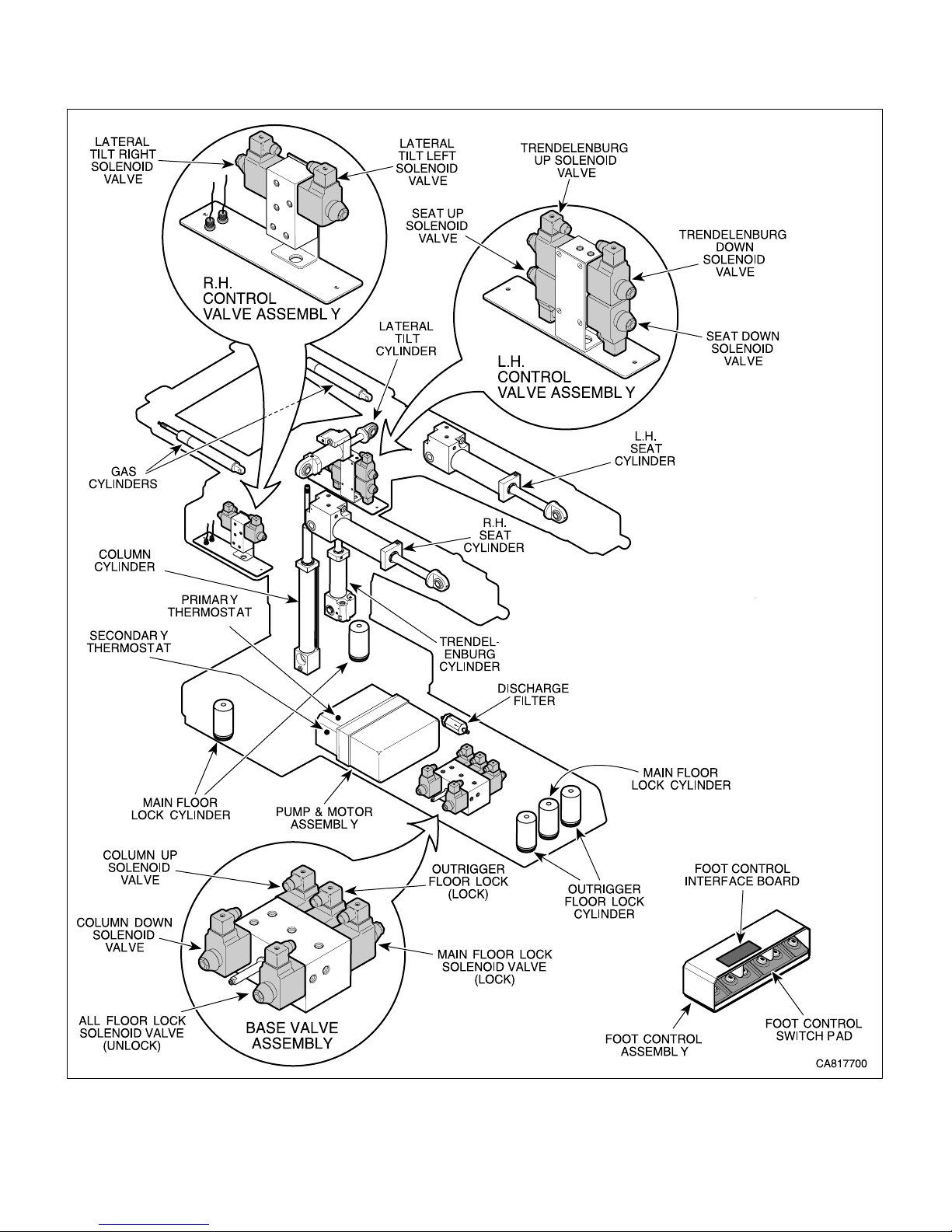
B. Theory of Operation. See Figures 5-1, Sheets 1
and 2, and Figure 5-2 for electrical schematic /
wiring diagram. See Figure 5-3 for hydraulic
schematic.
Electrical Theory Of Operation
When power cord is plugged into power cord recep-
tacle, line voltage (approximately 115 VAC) is supplied
to table. Line voltage is applied across an RFI filter.
RFI filter reduces line conducted RFI / EMI that is
present on incoming power line. Across RFI filter
output is a line power pilot lamp which illuminates to
indicate power is present at output of RFI filter.
Transformer primary lines are also connected across
RFI filter output. Transformer steps line voltage down
to 32.5 VAC ± 2 VAC. The 32.5 VAC from output of
transformer is applied to charging / power driver board.
Charging / power driver board uses a DC rectifying
circuit to convert 32.5 VAC to approximately 27.8 VDC.
Charging / power driver board regulates charging rate
of four batteries by regulating rate at which 27.8 VDC is
applied to batteries. Charging / power driver board also
supplies 27.5 VDC to main controller board to power it.
Transformer has thermal fuses connected in each
primary winding and they are embedded between the
primary and secondary windings. If transformer over-
heats, normally closed (N.C.) thermal fuses open,
disconnecting power to transformer.
Transformer is primarily used to supply power to
charging / power driver board, so board can charge
batteries and supply power to rest of table.
Charging / power driver board regulates charge rate
of batteries when batteries are being charged. This
means that a full load is not continuously being placed
on transformer, which is important because transformer
is not sized to draw a full current load continuously. If
batteries are low and a function is selected, power to
drive motor pump(s) is drawn from batteries first and
then from transformer as necessary. If batteries are too
low or a function is selected for too long, continuous
current draw thru transformer will overheat transformer
very quickly, causing thermal fuses to blow.
CAUTION
It is important that a table with a low bat-
tery charge be operated only in case of
emergency and for a very short time period (less
than a minute).
Logic Theory Of Operation
When ENABLE button is pressed, a 5 VDC signal is
sent to main controller board, activating it. Main
controller board performs a self diagnostic check on
itself. If self diagnostic check fails, error code E11
(Internal RAM / Register Failure) is displayed on hand
control.
Main controller board and charging / power driver board
uses status circuits to check functionality of following
electrical components: motors, charging / power driver
board, valve spool solenoids, main controller board,
position sensors, foot control switch pad, and hand
control button board.
A status circuit, on charging / power driver board,
monitors amount of current draw thru motor pump
windings, when a function has been selected. If current
draw exceeds a predetermined value, main controller
board stops all functions and displays error code E02
(Overcurrent - Motor Pump #1) or E03 (Overcurrent -
Motor Pump #2), which indicates a failure of a motor
pump.
If current draw falls below a predetermined value, main
controller board stops all functions and displays error
code E04, which indicates failure of charging / power
driver board.
A status circuit, on main controller board, monitors
enable circuitry for each valve spool solenoid and
detects if a valve spool solenoid or enable circuitry of
main controller board is functioning correctly. If not,
main controller board stops all functions and displays
error code E05 (Valve Drive Failure), which indicates
failure of either a valve spool solenoid or main controller
board.
Another status circuit, on main controller board, moni-
tors voltage input from position sensors. If voltage
value exceeds or falls below a predetermined range,
main controller board stops all functions and displays
appropriate error code: E07 (Trendelenburg Position
Sensor Failure), E08 (Tilt Position Sensor Failure), E09
(Seat Position Sensor Failure). An error code indicates
failure of either a position sensor, main controller board,
or wiring.
Main controller board also monitors main floor lock
status switch, outrigger floor lock status switch, motor
pump #1 primary thermostat, and motor pump # 2
primary thermostat. When hand control is ENABLED,
main controller board checks if normally open (N.C.)
main floor lock status switch and outrigger floor lock
status switch is untripped. If main controller does not
detect that
both
status switches are untripped, it
energizes main floor lock valve spool and motor pump,
causing main floor locks to extend. After eight seconds,
main controller de-energizes main floor lock valve spool
Page 1-4Printed in U.S.A.©SchaererMayfieldUSA,Inc.2004

SECTION I
GENERAL INFORMATION
Hydraulic System Theory Of Operation
When a function is selected using hand control or foot
control, motor pump(s) begins to run and selected
function's valve spool shifts.
Hydraulic oil flows thru a strainer in reservoir and into
pump chamber. Pump pumps oil thru an internal check
valve, and a discharge filter. Oil is now in supply line,
ready to power selected function's cylinder(s). Motor
pump internal check valve allows oil to flow thru to the
supply line, but closes when motor pump stops running,
preventing oil from back flowing into motor pump, which
prevents gravity drain out of supply line and back into
motor pump. Discharge filter removes any contami-
nants from oil before oil reaches any hydraulic compo-
nents. This prevents reduced life expectancy of
hydraulic components such as seals and o-rings and
prevents clogging of valves and check valves.
There is a 250 BAR (3625 PSI) pressure relief valve on
each motor pump. If pressure reaches or exceeds this
pressure, valve opens dumping oil back into reservoir.
Oil is now in supply line, ready to power selected
function's cylinder(s).
Trendelenburg and Lateral Tilt
If
Trendelenburg
or
Lateral Tilt Left
button on hand
control was selected (in normal table orientation), motor
pump is energized and valve spool for that function
moves to an up function position (oil will now flow in
new oil flow path that has been created; this path is
shown by straight flow symbols on hydraulic schematic)
and oil flows thru a check valve (A) and into the base of
cylinder, extending cylinder. Check valve (A) prevents
oil from escaping from cylinder after valve spool is de-
energized, keeping cylinder from drifting. Oil also flows
thru a pilot line (represented by a dashed line on
hydraulic schematic) and extends a pilot piston. Pilot
piston forces open check valve (B) on retracting side of
cylinder, allowing oil to escape from top side of cylin-
der, thru valve spool and into the oil return line.
If
Reverse Trendelenburg
or
Lateral Tilt Right
button on
hand control was selected (in normal table orientation),
motor pump is energized and valve spool for that
function moves to a down function position (oil will now
flow in new oil flow path that has been created; this path
is shown by crossed flow symbols on the hydraulic
schematic) and oil flows thru a check valve (B) and into
top of cylinder, retracting cylinder. Check valve (B)
prevents oil from escaping from cylinder after valve
spool is de-energized, keeping cylinder from drifting.
Oil also flows thru a pilot line (represented by a dashed
line on hydraulic schematic) and extends a pilot piston.
and motor pump, and then energizes outrigger floor
lock valve spool and motor pump, causing outrigger
floor locks to extend. After six seconds, main controller
de-energizes outrigger floor lock valve spool and motor
pump. At this time main controller checks status of
status switches again. If main controller does not
detect that
both
status switches are untripped, it stops
all functions and displays E01 (Floor Lock Status
Switch Is Not Responding).
Also, when hand control is ENABLED, main controller
board checks if normally closed (N.C.) motor pump
primary thermostats are closed. If main controller
board detects an open circuit, it stops all functions and
displays error code E13 (Overheat - Motor Pump #1) or
E14 (Overheat - Motor Pump #2), which indicates that
motor pump has overheated, opening its primary
thermostat.
Also, when hand control is ENABLED, main controller
board checks status of each set of switches in hand
control; there are two normally open (N.O.) switches for
each function, one for solenoid valve and one for motor.
If only one of the set of two switches is detected as
being pressed, main controller board detects this and
displays error code E15 (Hand Control Switch Failure).
This indicates that one switch is stuck in closed posi-
tion. Also, if a function button is pressed and then error
code E15 displays, this indicates that only one of two
switches is working properly. This safety feature
prevents unintended table movement due to a switch
malfunction.
Also, when a function is selected using foot control,
main controller board checks status of each set of
switches in the foot control pad; there are two normally
open (N.O.) switches for each function. If there is a set
of switches for which only one of two switches is
detected as being pressed, the main controller board
detects this and displays error code E06 (Foot Switch
Failure) on hand control. This indicates that one of two
switches is stuck in closed position or not working
properly. This safety feature prevents unintended table
movement due to a switch malfunction.
Motor pumps also have secondary thermostats which
provide backup protection if primary thermostats fail. If
a motor pump overheats and its primary thermostat
does not shut off motor pump, normally open (N.O.)
secondary thermostat closes, directly shorting current
past motor windings to ground, causing 40 amp fuse on
charging / power driver board to blow, which stops
motor pump.
Page 1-5Printed in U.S.A.©SchaererMayfieldUSA,Inc.2004

SECTION I
GENERAL INFORMATION
Pilot piston forces open check valve (A) on base of
cylinder, allowing oil to flow from base of cylinder, thru
valve spool, and into oil return line.
Seat Functions
If
SEAT UP
button on hand control is selected (in
normal table orientation), motor pump is energized and
valve spool for that function moves to an up function
position (oil will now flow in new oil flow path that has
been created; this path is shown by straight flow
symbols on hydraulic schematic) and oil flows thru a
check valve (A) and into base of left cylinder (master
cylinder), extending cylinder. Check valve (A) prevents
oil from escaping from cylinder after valve spool is de-
energized, keeping cylinder from drifting. Oil also flows
thru two pilot lines (represented by dashed lines on
hydraulic schematic) and extends two pilot pistons (B
and D). One pilot piston forces open a check valve (B)
which allows oil to flow out of top side of left cylinder
thru another check valve (C) and into base of right
cylinder (slave cylinder), extending cylinder. Other pilot
piston forces open check valve (D) on top side of right
cylinder (slave cylinder), allowing oil to flow from top
side of cylinder, flow thru valve spool and into oil return
line.
If
SEAT DOWN
button on hand control is selected (in
normal table orientation), motor pump is energized and
valve spool for that function moves to a down function
position (oil will now flow in new oil flow path that has
been created; this path is shown by crossed flow
symbols on hydraulic schematic) and oil flows thru a
check valve (D) and into top of right cylinder (slave
cylinder), retracting cylinder. Check valve (D) prevents
oil from escaping from right cylinder after valve spool is
de-energized, keeping cylinder from drifting. Oil also
flows thru two pilot lines (represented by dashed lines
on hydraulic schematic) and extends two pilot pistons.
One pilot piston forces open a check valve (C) which
allows oil to flow out of base of right cylinder thru
another check valve (B) and into top side of left cylinder
(master cylinder), retracting cylinder. Other pilot piston
forces open check valve (A) on base of left cylinder
(master cylinder), allowing oil to flow out of base of
cylinder, thru valve spool, and into oil return line.
Column Functions
If
TABLE UP
button on hand control is selected, motor
pump energizes and valve spool for that function moves
to an up function position (oil will now flow in new oil
flow path that has been created; this path is shown by
straight flow symbols on hydraulic schematic) and oil
flows thru a check valve (A) and into base of column
cylinder, extending cylinder. Check valve (A) prevents
oil from escaping from column cylinder after valve spool
is de-energized, keeping cylinder from drifting. Oil flows
out of top side of column cylinder as necessary, thru
valve spool, and into return line.
If
TABLE DOWN
button on hand control is selected,
motor pump energizes and valve spool for that function
moves to a down function position (oil will now flow in
new oil flow path that has been created; this path is
shown by crossed flow symbols on hydraulic sche-
matic) and oil flows to top side of base cylinder, retract-
ing cylinder. Oil also flows thru a pilot line (represented
by a dashed line on hydraulic schematic) and extends a
pilot piston. Pilot piston forces open check valve (A) on
base of cylinder, allowing oil to flow out of base of
cylinder, thru valve spool, and into oil return line.
Floor Lock Functions
If
ENABLE / LOCK
button on hand control is selected,
motor pump energizes and valve spool for main floor
lock cylinders moves to an up function position (oil will
now flow in new oil flow path that has been created; this
path is shown by straight flow symbols on hydraulic
schematic) and oil flows thru a check valve (A) and into
base of three main floor lock cylinders, extending
cylinders. Check valve (A) prevents oil from escaping
from three main floor lock cylinders after valve spool is
de-energized, keeping cylinders from drifting.
After approximately 10 seconds, main controller board
de-energizes motor pump and main floor lock spool and
then reenergizes motor pump and energizes outrigger
floor lock valve spool to an up function position (oil will
now flow in new oil flow path that has been created; this
path is shown by straight flow symbols on hydraulic
schematic) and oil flows thru two check valves (B and
C) and into the base of two outrigger floor lock cylin-
ders, extending cylinders. As soon as pressure in
outrigger floor lock cylinders reaches 10 BARS (145
PSI), outrigger pressure relief valve opens, dumping oil
back to return line. Outrigger cylinders were designed
to add stability to table on an uneven floor.
Three main floor lock cylinders lift table off of casters;
then the two outrigger floor lock cylinders extend with
enough power to stabilize table
without
lifting
table
further.
Check valves (B and C) prevent oil from escaping from
two outrigger floor lock cylinders after valve spool is de-
energized, keeping cylinders from drifting.
If
UNLOCK & ENABLE
buttons on hand control is
selected for three seconds, motor pump energizes and
main floor lock valve spool moves to a down function
position (oil will now flow in new oil flow path that has
been created; this path is shown by crossed flow
Page 1-6Printed in U.S.A.©SchaererMayfieldUSA,Inc.2004

SECTION I
GENERAL INFORMATION
symbols on hydraulic schematic). Oil flows thru three
pilot lines (represented by dashed lines on hydraulic
schematic) and extends three pilot pistons, which
forces open three check valves; check valves A, B, and
C. With all three check valves open, oil flows out of
base of three main floor lock cylinders and two outrigger
floor lock cylinders, causing them to retract. There is a
strong spring in each floor lock cylinder which helps
retract cylinder.
Seat Slave Line Valve
On the seat functions, there is a manually operated two
way-valve (slave line valve) which is used to add or
remove oil from closed loop (slave line) to synchronize
stroke of left (master) and right (slave) cylinders.
Column Slave Line Valve
There is a manually operated two-way valve (slave line
valve) on column function, which is used to add or
remove oil from middle stage of column cylinder (if
there is too much oil in second stage, column cylinder
will "jump" downward and make a noise when column
down function is selected. If there is not enough oil in
second stage, full height potential of column cylinder
will not be reached).
Orifices
Orifices are internal to Trendelenburg, Lateral Tilt, and
Seat, cylinders to meter flow of oil into cylinders,
thereby regulating speed of cylinders.
1.4 SPECIFICATIONS
Factual data for the 7300 Modular Surgery Table is
provided in Table 1-1.
Table 1-1. Specifications
Description Data
Weight
Normal (w/ head & pelvic sections & upholstery)...........
........................................................... 660 lb. (299 kg)
With Shipping Carton.......................... 764 lb. (347 kg)
Shipping Carton........ 58 in. "L" x 30 in. "W" x 40 in. "H"
(147 cm x 76 cm x 102 cm)
Dimensions: (w/ Head, Back, Pelvic & Leg Transfer
Board.)
Table Top Length ............................. 75.6 in. (192 cm)
Table Top Width ...................................... 20.5 (52 cm)
Overall Width......................................... 24 in. (61 cm)
Overall Length ..................................... 78 in. (198 cm)
Table Positioning:
Table Top Height (Adjustable) .......... 27.7 (± 0.2) in. to
43.9 (± 0.2) in.
(70 to 112 cm)
Trendelenburg ......................................0° to 28° (±1°)
Reverse Trendelenburg....................... 0° to -28° (±1°)
Lateral Tilt................ 0° to -18° (±1°) in either direction
Seat Section .......... + 75° (±1°) to -40° (±1°) in relation
to back section
Coordinating Flex (Normal Position):
Trendelenburg ................+20° (±5°) above horizontal
Seat Section ......-40° (±5°) in relation to back section
Coordinating Reflex (Normal Position):
Trendelenburg ................. -28° (±5°) below horizontal
Seat Section .....+60° (±5°) in relation to back section
Head Section:
Mounted on Head End...........+30° (±3°) to -30° (±3°)
Mounted on Foot End ............+30° (±3°) to -75° (±5°)
Page 1-7Printed in U.S.A.©SchaererMayfieldUSA,Inc.2004

SECTION I
GENERAL INFORMATION
Table Speed (Table in normal orientation, full battery
charge, ambient oil temp.):
Extend Column Fully .................. 16.0 to 21.0 seconds
Retract Column Fully.................. 16.0 to 21.0 seconds
Reverse Trend. to Trend. ........... 20.5 to 24.5 seconds
Trend. to Reverse Trend. ........... 16.0 to 20.0 seconds
Lat. Tilt R to Lat. Tilt L .................. 9.5 to 12.5 seconds
Lat. Tilt L to Lat. Tilt R ................ 10.0 to 13.0 seconds
Seat Down to Seat Up ................ 18.0 to 21.0 seconds
Seat Up to Seat Down ................ 18.5 to 21.5 seconds
Weight Capacity (maximum):
Normal Table Orientation ..................500 lbs. (227 kg)
Reverse Table Orientation..............400 lbs. (181.4 kg)
Head Section.........................................40 lbs. (18 kg)
Overweight Operation ................ Patient Positioning is
restricted. To learn of limita-
tions, contact the Surgical
Table Product Manager at
1-800-643-6275
Hydraulic System Oil ................ ISO Viscosity Grade 32
Premium Hydraulic Fluid
Reservoir Capacity ..................... 2.1 Quarts (2.0 Liters)
System Capacity ........................ 3.7 Quarts (3.5 Liters)
Battery Charging Time.............................. 8 to 12 hours
Motor Pump Pressure
Relief Valve ...............Opens At 250 BARS (3625 PSI)
Outrigger Pressure
Relief Valve ...................Opens At 10 BARS (145 PSI)
ElectricalRequirements:
115 VAC Unit........................... 110 - 120 VAC, 60 HZ,
2 amp, single phase
Battery Power Output ............ 24 VDC, 18 amp-hours
1.5 Parts Replacement Ordering
If a part replacement is required, order the part directly
from the factory as follows:
(1) Refer to Figure 1-2 to determine the location of
the model number and serial number of the unit
and record this data.
(2) Refer to the Parts List to determine the item
numbers of the parts, part numbers of the
parts, descriptions of the parts, and quantities
of parts needed and record this data (Refer to
para 6.1).
NOTE
Ask the Purchasing Department of the company that
owns the unit for this information. Otherwise, this
information may be obtained from the dealer that
sold the unit.
(3) Determine the installation date of the unit and
record this data.
Please have the Model and
Serial Number when contacting SMI
(4)Call SMI with recorded information and ask
for Technical Services Department. Use phone
number 1-800 643-6275
Figure 1-2. Model Number / Serial
Number Location
Page 1-8Printed in U.S.A.
SMI 7100
MODEL
NUMBER
SERIAL
NUMBER
SMI
7100-001
115 VAC
2 AMP 60 HZ
TDWXXXXX
MODEL
INPUT
RATING
SERIAL NO.
CA7681
©SchaererMayfieldUSA,Inc.2004

SECTION I
GENERAL INFORMATION
Page 1-9Printed in U.S.A.
1.6 Special Tools
Table 1-2 lists all of the special tools needed to repair
the unit, how to obtain the special tools, and the pur-
pose of each special tool.
Table 1-2 is on the following page.
Table 1-2. Special Tools List
Description of Special Tool Manufacturer's
Name / Address / Phone Manufacturer's
Part Number Purpose of Special Tool
Multimeter Commercially Available Any Type Used to perform continuity and voltage checks.
Pin Extractor (has
interchangable bits - M3x0.5,
M4x0.7, M5x0.8, M6x1.0,
1/4-20, 10-24, and 5/16-18)
Schaerer Mayfield USA
4900 Charlemar
Drive Cincinnati, Ohio 45227
(800) 755-6381
M05390 Used to pull pins which secure cylinders, handles,
etc. in place. Can also be used to remove caster
fork.
Spanner Wrench - locking nut Schaerer Mayfield USA
4900 Charlemar
Drive Cincinnati, Ohio 45227
(800) 755-6381
M07235 Used to remove locking nut which secures top of
column cylinder in column.
Spanner Wrench - brass pivot
puck Schaerer Mayfield USA
4900 Charlemar
Drive Cincinnati, Ohio 45227
(800) 755-6381
M07236 Used to remove brass pivot puck which secures
top of column cylinder in column.
Retaining Bolt Schaerer Mayfield USA
4900 Charlemar
Drive Cincinnati, Ohio 45227
(800) 755-6381
M07407 Used to hold rod of column cylinder stationary,
while special tools, M07235 and M07236 are
used.
Spanner Wrench - retainer cap Schaerer Mayfield USA
4900 Charlemar
Drive Cincinnati, Ohio 45227
(800) 755-6381
M07161 Used to remove retainer cap which secures
latching mechansim in place.
Pressure Relief Valve Test
Harness Schaerer Mayfield USA
4900 Charlemar
Drive Cincinnati, Ohio 45227
(800) 755-6381
M07443 Used to adjust crack settings of motor pump
pressure relief valves and outrigger pressure relief
valve.
Blanking Plug Kit Schaerer Mayfield USA
4900 Charlemar
Drive Cincinnati, Ohio 45227
(800) 755-6381
502-0176-00 Used to cap the end of hydraulic lines to allow
pressure checks to be made.
Soldering Iron Commercially Available Any Type Used to connect wires to terminals with solder.
60 / 40 Solder Commercially Available Any Type Type of solder which should be used when
soldering wires on surgery table.
Internal retaining ring pliers Commercially Available Any Type Used to remove snap rings which secure bearings
in base of cylinders.
Torque Wrench Commercially Available Any Type Used to tighten hardware to specified torque
values.
Transport Tool Schaerer Mayfield USA
4900 Charlemar
Drive Cincinnati, Ohio 45227
(800) 755-6381
502-0169-00 A dolly type tool which is used to transport Model
7100 or 7300 surgical tables around.
Tipping Tool Schaerer Mayfield USA
4900 Charlemar
Drive Cincinnati, Ohio 45227
(800) 755-6381
502-0168-00 Used to tip over Model 7100 or 7300 surgical
tables to access base of table for servicing.
©SchaererMayfieldUSA,Inc.2004

SECTION I
GENERAL INFORMATION
Page 1-10Printed in U.S.A.
©SchaererMayfieldUSA,Inc.2004

SECTION II
TESTING AND TROUBLESHOOTING
2.1 Operational Test
In order to effectively diagnose malfunctions of the 7300
Modular Surgical Table, it may be necessary to perform
an operational test as follows:
DANGER
Refertothe OperatorManualfor
completeinstructionsonoperatingthe
surgical table. Failure to do so could result in
personalinjury.
Power must be supplied to the unit to measure
the voltage at the Test Points. Do not touch any
bare wires or terminals while making these
voltage checks. Failure to do so may result in
electrical shock which could result in serious
personal injury or death.
NOTE
The Operational Test, for the most part, only de-
scribes what should happen when the surgical table is
operated. If the surgical table does something other
thandescribed, a problemhasbeendiscovered.
RefertotheTroubleshootingGuideto determinethe
cause of the problem and its correction.
(1) Plugpowercordintotable'splugreceptacle.
See Figure 2-1, Sheets 1 and 2.
(2) Observe. Theline power pilot lampshould
illuminate.
(3) Unplugthepowercord.
(4) Press ENABLE button on hand control.
(5) Observe. Thehand control display should
illuminate and display the current table position
and battery charge level (XX POSITION and
BATT LEVEL XX. After 10 seconds, the hand
control display should extinguish.
(6) Press and hold UNLOCK & ENABLE buttons on
handcontrolfor three seconds.
(7) Observe. Themotor pump should run andthe
table should lower (floor lock cylinders should
retract) until table is on its casters. The hand
controldisplayshouldreadUNLOCKING
FLOORandthenONWHEELS.
SECTION II
TESTING ANDTROUBLESHOOTING
(8) Movethe surgerytablearound.
(9) Observe. The casters should swivel freely and
the table should roll easily on the casters. The
tableshouldnotwobble.
(10) Press ENABLE button on hand control.
(11) Observe. Themotor pump should run andthe
main floor lock cylinders should extend. After
eight seconds, the motor pump should stop
running. Thenthemotor pump should begin
runningagainandtheoutriggerfloorlock
cylinders should extend. After six seconds, the
motorpumpshould stop running. The hand
controldisplayshouldreadLOCKINGFLOOR
while the floor lock cylinders are extending.
(12) Insert pins of Head Section into sockets on
column end of table. Rotate latch handles to
locked position (to move latch handles to locked
position, rotate them away from you) and then
pull and push on head sections.
(13) Observe. When the latch handles are rotated to
the locked position, the section being installed
should now be held securely in place. No side-
to-sideorin-and-outmovementshouldbe
possible.
(14) Press the ENABLE and REVERSE POSITION
buttonsonhandcontrol.
(15) Observe. Thehandcontroldisplayshouldread
REVERSE POSITION.
(16) Press the FLEX button and then REFLEX
button.
(17) Observe. Handcontroldisplay should indicate
these positions are "disabled" and cannot be
used when table is in REVERSE POSITION.
(18) Press the ENABLE and NORMAL POSITION
buttonsonhandcontrol.
(19) Observe. Thehandcontroldisplayshouldread
NORMALPOSITION.
©SchaererMayfieldUSA,Inc.2004 Page2-1 PrintedinU.S.A.

SECTION II
TESTING AND TROUBLESHOOTING
Figure 2-1. Operational Test (Sheet 1 of 2)
Page2-2PrintedinU.S.A.
CA819700
SMI 7300
LEVEL UNLOCK
ENABLE
LOCK DISABLE
7100
SMI
EMERGENCY
OVERRIDE
PANEL
FOOT
CONTROL
HAND
CONTROL
LATCH
HANDLE
SEAT SECTION
(PELVIC BASE)
BACK
SECTION
FLOOR
LOCK
CYLINDERS
SMI
7300
POWER
CORD
LINE POWER
PILOT LAMP
PLUG
RECEPTACLE
TRENDEL-
ENBURG
REVERSE
TRENDEL-
ENBURG
TABLE
UP
TABLE
DOWN
LATERAL
TILT
RIGHT
LATERAL
TILT
LEFT
RELEASE
HANDLE
HEAD
SECTION
A
B
C
LOCKED
POSITION
AUTO
CAPTURE
POSITION
UNLOCKED
POSITION
LATCH HANDLE
POSITIONS
(TYP. 2 PLACES)
©SchaererMayfieldUSA,Inc.2004

SECTION II
TESTING AND TROUBLESHOOTING
Figure 2-1. Operational Test (Sheet 2 of 2)
(20) Press the ENABLE button and then press the
TABLE UP, TABLE DOWN,
TRENDELENBURG,REVERSE
TRENDELENBURG,LATERALTILTLEFT,
LATERAL TILT RIGHT, SEAT UP, SEAT
DOWN,FLEX, and REFLEX buttons,running
each function thru its full range of motion, and
checking its speed and range of motion perfor-
mance.
(21) Observe. Thetableperformanceshouldmeet
the following specifications:
RangeOfMotion:
TableTopHeight(Adjustable) ........... 27.7 (± 0.2) in. to
43.9 (± 0.2) in.
(70 to 112 cm)
Trendelenburg ....................................... 0° to 28° (±1°)
ReverseTrendelenburg ......................... 0° to-28°(±1°)
Lateral Tilt................. 0° to -18° (±1°) in either direction
Seat Section ........... + 25° (±1°) to -40° (±1°) in relation
to back section
CoordinatingFlex(NormalPosition):
Trendelenburg ..................+20°(±5°)abovehorizontal
CoordinatingReflex(NormalPosition):
Trendelenburg ................... -12°(±5°)belowhorizontal
Table Speed (Table in normal orientation, full battery
charge,ambientoil temp.):
ExtendColumn Fully................... 16.0 to 21.0 seconds
RetractColumnFully .................. 16.0 to 21.0 seconds
ReverseTrend.toTrend. ............ 20.5 to 24.5 seconds
Trend.toReverseTrend. ............ 16.0 to 20.0 seconds
Lat. Tilt R to Lat. Tilt L .................. 9.5 to 12.5 seconds
Lat. Tilt L to Lat. Tilt R ................ 10.0 to 13.0 seconds
Seat Down to Seat Up ................ 18.0 to 21.0 seconds
Seat Up to Seat Down ................ 18.5 to 21.5 seconds
Page2-3PrintedinU.S.A.
CA819800
BUTTONS
NORMAL
POSITION
REVERSE
POSITION
TREND REV TREND
HEIGHT UP HEIGHT DOWN
TILT L TILT R
SEAT UP SEAT DOWN
FLEX REFLEX
ENABLE DISABLE
LOCK
UNLOCKLEVEL
SMI
7300
SMI
7300
DISABLE
SYSTEM
OVERRIDE
UNLOCKLOCK
LATERAL
TILT LEFT
SEAT
UP
REVERSE
TRENDELENBURG
LATERAL
TILT RIGHT
SEAT
DOWN
UNLOCK
TABLE
DOWN
TABLE
UP
DISABLE
SYSTEM
OVERRIDE
LEVEL
(RETURN TO)
TRENDELENBURG
ENABLE
TRENDELENBURG
LATERAL
TILT LEFT
SEAT
UP
REVERSE
POSITION
REVERSE
TRENDELENBURG
LATERAL
TILT RIGHT
SEAT
DOWN
NORMAL
POSITION
REFLEX
UNLOCK
LEVEL
(RETURN TO)
FLEX
TABLE
DOWN
TABLE
UP
DISABLE
HAND
CONTROL
DISPLAY
©SchaererMayfieldUSA,Inc.2004

SECTION II
TESTING AND TROUBLESHOOTING
(22) Press the ENABLE button and then press the
LEVEL button until the table reaches its level
position. Using a protractor, check the table top
to ensure it is level within ±2°.
(23) Observe. The table top should move to a level
position within ±2° as follows: The lateral tilt
function should level out first; then a sequence
ofthe Seat, andTrendelenburgfunctionsshould
move, with each function moving no more than
10° at a time.
(24) Squeezethereleasehandle on the head section
and move the head section thru its full range of
motion.
(25) The head section should move smoothly and
should not take excessive force. The head
section should meet the following range of
motion specifications:
HeadSection:
Mounted on Head End ........... +30° (±3°)to-30° (±3°)
Mounted on Foot End ............ +30°(±3°)to-75°(±5°)
(26) Move head section to level position and then
place approximately 40 lbs. (18 kgs) at Point C
(head section). Observe head section for two to
threeminutes.
(27) Observe. The head section should not drift.
(28) Place approximately 400 lbs. (181.4 kg) of
weight on table top as follows: 28 lbs. (12.7 kg)
at Point C (head section), 152 lbs. (69 kg) at
Point B (back section), and 168 lbs. (76.2 kg) at
Point A (seat section).
(29) Press ENABLE button and then press TABLE
UP and TABLE DOWN buttons to run column
function up and down several times.
(30) Observe. Columnfunction should move upand
down steadily and smoothly. No binding
conditionshouldbe evident, especially when
column is lowering. There should be no exces-
sive side-to-side play in column assembly.
(31) Removeweightfrom table top.
(32) Press and hold the SYSTEM OVERRIDE button
while pressing the function buttons, one at a
time,onthe emergency override panel.
(33) Observe. Each function should move as
depicted by the illustration on its button.
(34) Press each function button on the foot control.
Then place the table top in REVERSE position.
Then press each function button on the foot
controlagain.
(35) Each function should move as depicted when
table top is in NORMAL position. The table
should not operate, using the foot control, when
the table top is in REVERSE position.
(36) Plugpowercordintotable'spowerreceptacle.
DANGER
Electricalpower mustbe connected to
perform the following steps. Do not
touch any bare wires or terminals. Failure to do
so could cause an electrical shock which could
result in serious personal injury or death.
(37) See Figure 2-2 for this step. Check for 32.5
VAC ± 2 VAC across Test Points C and D and
across Test Points D and E.
(38) Observe. There should be 32.5 VAC ±2 VAC
across
both
sets of test points.
(39) See Figure 2-2 for this step. Check for 27.7
VAC ± 2 VAC across Test Points F and G and
across Test Points H and J. Check for 27.8
VAC ±2 VAC across Test Points K and L.
(40) Observe. Theproper voltages shouldbe
present across
each
set of test points.
Page2-4PrintedinU.S.A.
©SchaererMayfieldUSA,Inc.2004
Other manuals for 7300
1
Table of contents
Other Schaerer Medical Equipment manuals
Popular Medical Equipment manuals by other brands

Aesculap
Aesculap ELAN 4 Instructions for use/Technical description

Enabling Devices
Enabling Devices 1684 user guide

Bioness
Bioness NESS L300 Clinicians Guide

Hico Medical Systems
Hico Medical Systems HICO-VARIOTHERM 550 Instructions for use

Zeiss
Zeiss opmi lumera 700 user manual

Carestream HEALTH
Carestream HEALTH DRX-1 System Hardware user's guide

gbo
gbo Stereodynator Service manual

SUMED
SUMED Integrity Quick setup guide

OYMotion Technologies
OYMotion Technologies OHand2CH OYM-OH-A001LS-B001 user guide

NeuroMetrix
NeuroMetrix NC-stat DPNCheck reference guide

DTF
DTF PURENEB CLASSIC AEROLIGHT Instructions for use

CORIN
CORIN OPS Product overview and surgical technique