Darfon PVI5000 User manual

Installation and Operating
Manual

2
1. Introduction
1.1 General
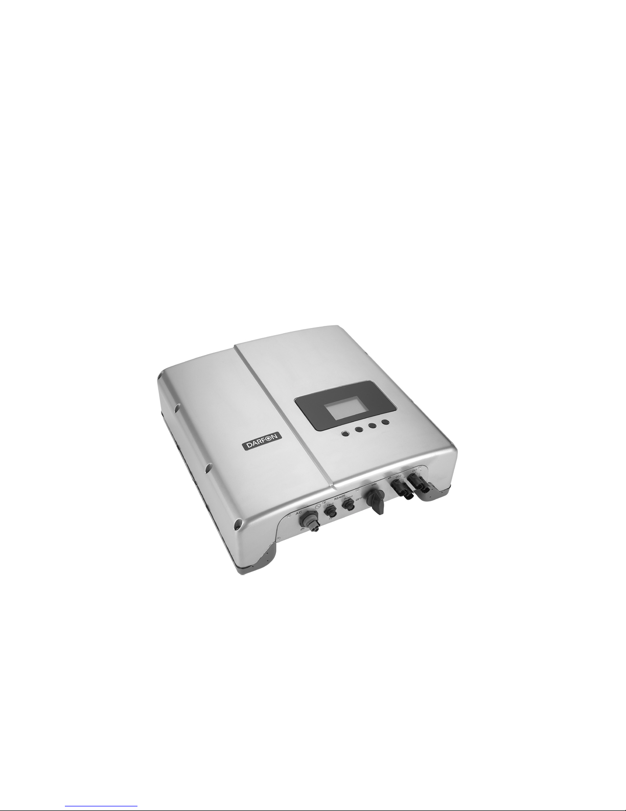
Thank you for choosing Darfon PVI5000 inverters as your power
conversion devices in the solar power system. This document
contains important information for the installation and settings of
this product. Therefore, before you start the installation and settings,
it is highly recommended to read this manual carefully.
The use of string PV concept significantly reduces the cabling costs
on a photovoltaic system. The use of just two parallel strings of PV
modules in series has proven advantageous by delivering a high
operating voltage to the solar inverter.
This advantage is primarily reflected in a higher efficiency of the
inverter. Careful optimization of the overall inverter system’s cost
and efficiency lead to the choice of a 550V DC maximum system
voltage for the PVI5000 for use with 1 kW to 5.3 kWPV arrays per
inverter.
The PVI5000 inverter is designed to cover solar electric power into
utility grade electricity that can be used by home or local power
company.
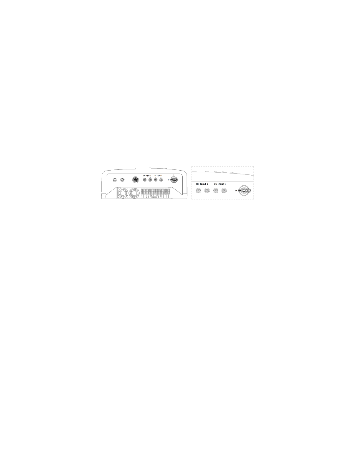
PVI5000 inverter is designed to support two (2) PV strings and
operate automatically without any configuration once it is installed
and commissioned according to the technical specifications. When
at least one of the DC input voltages generated by the photovoltaic
module goes above the initial voltage setting and under the pre-set
threshold value, the embedded controller is then waked up and
goes through the checking mode and then stay at CNTing mode
because the pre-set threshold value is not reached yet. At this time,
the PVI5000 inverter would not feed the AC power to the mains
utility; instead, it keeps watching the input DC voltage. Once the
input DC voltage goes up above the pre-set threshold value and all

3
other conditions necessary for grid connection are checked and
fulfilled for a certain period of time, the PVI5000 inverter goes into
the Grid with MPPT mode that turns the AC relays on and begins
feeding the AC voltage into the grid steadily. When all of the input
DC voltages fall below the initial voltage setting which is 100Vdc,
the PVI5000 inverter will then shut itself down. The PVI5000
inverter will be waked up automatically when one or more of the
input DC voltages go up above the initial voltage setting.
Maximum power point tracking
The PVI5000 inverter use Darfon proprietary maximum power point
(MPPT) tracking technology to get the maximum amount of energy
form the solar array, which helps your arrays to have maximum
output at all times.

4
1.2 Specification Table
Model Name PVI 5000
Grid Side (AC output)
AC Nominal Voltage / Range
220-240 V / 180-280 V
AC Grid Frequency 50 / 60 Hz
Nominal Output Power 4600 W
Maximum Output Power 5000 W
Maximum Output Current 22 A
Waveform True sine
Power Factor > 0.99
THD < 3%
Phase Single
PV Side (DC input)
Maximum DC Power 5300 W
Maximum Input Voltage 550 VDC
MPP Voltage Range 130 V ~ 440 V
Peak Power Tracking Voltage
205 V ~ 440 V
Maximum DC Input Current 2 x 13 A
Number of MPP Tracker 2
Efficiency
Max. Efficiency > 96.5 %
Euro. Efficiency > 95.5 %
Consumption:
Operating(standby) / Night < 20 W / < 0.5 W

5
Model Name PV 5000
General Specification
Dimensions (W x H x D)
in mm 470 * 490 * 170
Weight / Shipping Weight 28 kg
Cooling Fan Controlled
Ambient Temperature Range
-20°C to 60°C
Protection Degree IP65
Topology Transformer-less
Others
DC Connection Tyco(Std.)/MC3(Opt.)/MC4(Opt.)
DC Switch Yes
AC Connection Plug-connector
Display Graphic LCD
Interface RS485/RS422
Certifications
EN 61000-6-2, EN 61000-6-3,
EN 61000-3-11,EN 61000-3-12,
VDE0126-1-1, IEC62109

6
1.3 Installing Accessories
Operating Manual x1
AC Connector x1
DC Connector (female) x2
DC Connector (male) x2
RS485/RS422 Connector x2
Bracket x1

7
2.Safety
2.1 Safety Notification
The PVI5000 inverters may contain high voltages and the risk of
electrical shock, even when no external voltage is present. Only the
trained qualified electrical personnel are allowed to perform the
electrical installation, wiring, opening, repair, and modification of the
PVI5000 inverters.
The temperature of the heat sinks outside of the device can reach
over 70°C in normal operation. There is risk of burn injury when
these parts are touched.
Before using this unit please read these operating instructions
carefully. Take special care to follow the warnings indicated in the
unit itself as well as the safety suggestion list below. Failure to
comply with these precautions or with specific warnings elsewhere
in this manual violates safety standards of design, manufacture,
and intended use of the device. The manufacturer assumes no
liability for the customer’s failure to comply with these requirements.

8
2.2 Safety Symbols
To reduce the risk of injury and to ensure the continued safe
operation of this product, the following safety instructions and
warnings are marked in this manual.
Warning, risk of electric shock
The lighting flash with arrowhead symbol,
within an equilateral triangle, is intended to
alert the user to the presence of dangerous
voltage with in the product’s enclosure that may
be constitute a risk of injury or death to users
and / or installers.
!
Caution (refer to accompanying documents)
The exclamation point within an equilateral
triangle is intent to alert the user to the
presence of important information to prevent
damage to this product.

9
2.3 Wiring the Inverter
The following three sections describe the connections of wirings for
the DC, AC, and communication ports. The PVI5000 has two (2)
pairs of DC connection terminals, string A and B. The DC
connection terminals are used to connect to PV strings through
circuit breakers. Each pair of the DC connection terminals shall be
connected to one PV string with the maximum rating value of
voltage and current. The AC connection terminal used to connect to
the main utility through a circuit breaker that shall be closed to the
distribution panel. The inverter has two (2) RS422/RS485
connectors, are used for external communication to a remote
computer or terminal.
Fig. 3.3.1 Wiring compartment bottom view

10
2.3.1 DC Cable Connection
The PVI5000 is designed to support two independent PV strings,
string A and B.
Each PV string shall provide a DC input voltage with maximum
power of 3000 W and maximum current of 12 A. The are two (2)
terminals, labeled as “+” and “-”, DC voltage input located on the
bottom of the inverter used for the DC cable connections.
Fig. 3.3.2.1 DC terminals for DC cable connection
Connect the Positive (+) wire from the #1 PV string to the PV1
(+) terminal. Double check the wire is in the proper location
and tight it with screw.
Connect the Negative (-) wire from the #1 PV sting to the PV (-)
terminal. Double check the wire is in the proper location and
tight it with screw.
Repeat for the #2 PV string, if there is one. Double check the
wire is in the proper location and tight it with screw.

11
!
CAUTION!
The DC voltage must be less than 550 V in any
condition.
WARNING!
Route the DC connection cables to the
PVI5000 inverters away from any possible
hazards that could damage the cables.
WARNING!
Allow at least 5 minutes for PVI5000 inverter
to discharge energy completely, since the
hazardous voltage will remand on the device
after disconnecting all PV DC input.
2.3.2 Communication Cable Connection
The PVI5000 inverter supports one common data interface
standards, RS485/RS422 that will be used to communicate to the
remote computer or terminal.

12
2.4 Operation Feature
(1)Independent / parallel mode automatic detection:
PVI5000 can provide two inputs in connection with PV
arrays, and it can detect automatically the connection type
of PV arrays; that is parallel or independent mode.
Through this convenient method, we give more flexible
connections of PV arrays for system installers. It lets the
system installers match the PV arrays with more
appropriate and optimum solutions and get more power
efficiency.
(2)Independent / parallel MPPT mode:
We provide two kinds of MPPT mode for PVI5000.They
are individually called parallel mode and independent
mode. While PVI5000 detect the connection type of PV
arrays is parallel mode, PVI5000 has one set of MPPT.
MPPT built in program can make the PV arrays achieve
the optimum power efficiency. In contrast, if PVI5000
detect the connection type of PV arrays is two individual
inputs, there will be two sets of MPPT making both of two
individually PV arrays attain the optimum power efficiency.
(3)Graphic display:
There is different from the traditional character displays,
and we adopt the graphic display as the measure of
showing messages for PVI5000. By the graphic display,
the users can understand the current operation status,
history information, power in accumulation and so on.
More details are referred to Chapter 4.4, and there will be
more contents and descriptions about it.
(4)Wide input voltage range:
PVI5000 can have the ability of wide input voltage range,
and it gets the system installers one good avenue to have
more economical and efficient combinations of PV arrays.
There will be good effects when PVI5000 matches well
with good selection of PV arrays combination

13

14
2.5 Technical Specifications
Model Name PVI 5000
Grid Side (AC output)
AC Nominal Voltage /
Range 220-240 V / 180-280 V
AC Grid Frequency 50/60 Hz
Nominal Output Power 4600 W
Maximum Output Power
5000 W
Maximum Output Current
22 A
Waveform True sine
Power Factor > 0.99
THD < 3 %
Phase Single
PV Side (DC input)
Maximum DC Power 5300 W
Maximum Input Voltage 550 VDC
MPP Voltage Range 130 V ~ 440 V
Peak Power Tracking
Voltage 205 V ~ 440 V
Maximum DC Input
Current 2 x 13 A
Number of MPP Tracker
2

15
Efficiency
Max. Efficiency > 96.5 %
Euro. Efficiency > 95.5 %
Consumption:
Operating(standby)/Night < 20 W / < 0.5 W
General Specification
Dimensions (W x H x D) in mm
430 * 495 * 166
Weight / Shipping Weight 28 kg
Cooling Fan Controlled
Ambient Temperature Rang -20°C to 60°C
Protection Degree IP65
Topology Transformer-less
Others
DC Connection Tyco(Std.)/MC3(Opt.)/MC4(Opt.)
DC Switch Yes
AC Connection Plug-connector
Display Graphic LCD
Interface RS485/RS422
Certifications
EN 61000-6-2, EN 61000-6-3,
EN 61000-3-11,EN 61000-3-12,
VDE0126-1-1, IEC62109

16
Manufactured by:
DARFON ELECTRONICS CORP.
167 Shan-ying Road, Gueishan,
Taoyuan 333, Taiwan, (R.O.C.)
Table of contents
Other Darfon Inverter manuals

Darfon
Darfon G640 User manual

Darfon
Darfon MIG240UL00 User manual

Darfon
Darfon G320 User manual

Darfon
Darfon H5001 User manual

Darfon
Darfon MIG300 User manual

Darfon
Darfon HB51 User manual

Darfon
Darfon H5001 User manual

Darfon
Darfon H5000 User manual

Darfon
Darfon H5001 User manual

Darfon
Darfon MIG240 User manual
Popular Inverter manuals by other brands

JED
JED 103 Installation and operation manual

Defort
Defort DCI-600 user manual

Volpi Tecno Energia
Volpi Tecno Energia PAGURO 4 SY owner's manual

Oilon
Oilon ECO Inverter+ 7 Installation and commissioning

SunSynk
SunSynk SUNSYNK-29.9K-SG01HP3-EU-BM3 Installer manual

Soltech
Soltech SOLPORT 15W installation manual