Quantum Harvest 2500 Series User manual

Quantum Harvest Model 2550-60 TSW
quantumharvest.net
Owner's Manual
Faraday
Enclosures
Portable Solar
Power Stations
®
®


Introduction
Congratulations on your purchase of a Quantum Harvest EMP protected* portable solar
power station! hese units have been carefully designed and hand-crafted to provide many
years of trouble-free operation. In the unlikely event of malfunction, we offer a 1 year warranty
on the batteries (if provided by us.); 3 years on the charge controllers; 5 years on everything
else. For warranty details, see page 34.
o obtain maximum performance and long life from your new power station, it is
important to gain a basic understanding of how such units operate and their limitations. he
heart of the unit, and it's main component, is the battery bank. his is where the energy from
the solar panels or the included 120 volt AC battery charger is stored for later use. he
particular batteries I have selected are state of the art deep-cycle Absorbed Glass Mat (AGM)
medical-grade batteries, designed for powered wheel chairs. hese batteries are maintenance
free and can be stored and used in any position. Since they do not give off gases as they charge,
there is no danger of fire and they never need to have water added.
o obtain maximum life from these, or any other batteries, it is important to try to avoid
deep cycling, that is, drawing them down flat before allowing them to recharge. Sometimes this
cannot be avoided, but if at all possible, strive to avoid doing so.
Another important component is the inverter. his is the device that converts the low
voltage DC current from the batteries into the high voltage AC current that we are familiar
with. (All Quantum Harvest power stations also have 12 volt DC receptacles and USB charging
sockets for the appropriate devices, in addition to standard 120 volt AC house current.) he
inverter is protected internally from overheating and low battery voltage, and externally from
over-current draw by a 300 ampere ANL type fuse. he Model 2550 will sustain a continuous
2000 watts of current, and will briefly provide up to 4000 surge watts, to start motors and other
inductive loads. he inverter relies on air flow around and through the unit to cool it, therefore
it is imperative that the inverter not be used with the enclosure door closed.
1

*A quick note on EMP
An EMP, or Electro-Magnetic Pulse is a devastating phenomenon that, while harmless to living
things, absolutely destroys anything electronic. t consists of extremely powerful electromagnetic fields
building and collapsing hundreds of thousands of times per second. This induces potentially huge
electric currents in anything that conducts electricity, causing components connected to said conductor
to burn out. An EMP can be caused by either a deliberate, high-altitude nuclear warhead detonation,
or can be caused naturally by a solar event called a Coronal Mass Ejection, or CME.
All Quantum Harvest power units are built into a specially designed enclosure, more
properly called a Faraday Cage, named after Michael Faraday, an early pioneer in
electromagnetic research. The purpose of a Faraday cage is to intercept and divert
electromagnetic energy away from the box's interior, thus protecting the contents.
The principles involved are fairly simple, but the proper execution is critical. n order
for the enclosure to be useful, it must have a door, but any opening larger than a square
centimeter or so allows too much energy to penetrate the interior, thus defeating the purpose of
the Faraday cage.
The solution to this conundrum is to gasket the door with a special type of conductive
gasket, mated to a copper or silver strip that is electrically bonded to the main box. The key is
to have very low electrical resistance between the door and the enclosure, with no gaps. This is
not as easy as it sounds, and requires special materials designed specifically for this
application.
My experience with Faraday apparatus comes from 8 years experience with very
powerful industrial machines called RF welders. These machines use extremely powerful and
focused bursts of electromagnetic energy to weld and form plastic parts. These machines
basically create a local EMP every time they fire, and it is critical that stray energy be confined
and dissipated safely to avoid damage to other sensitive electrical machinery.
==========================================================
Table of ontents
Specifications.......................................................................................Page 3
Note on Batteries.................................................................................Page 4
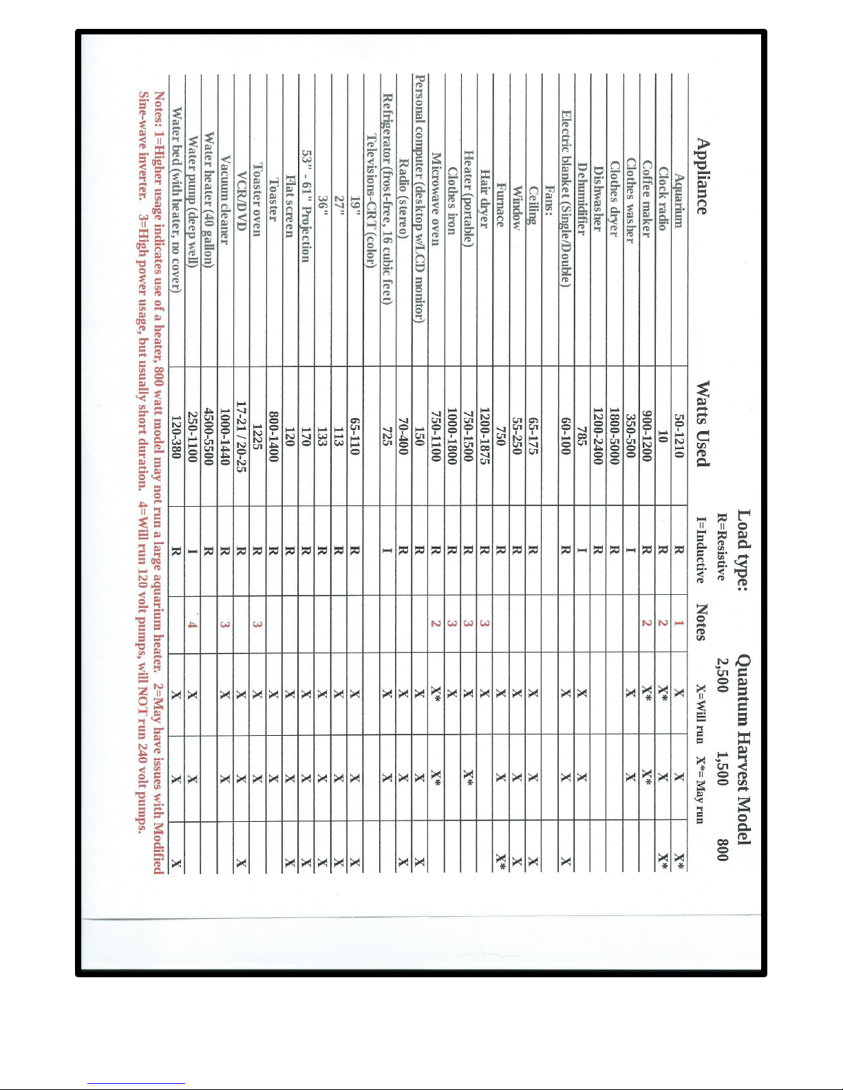
Section 1............ apacities and recommended usages.....................Page 5-6
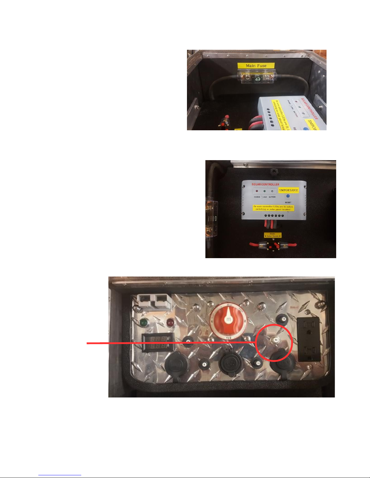
Section 2............ ontrols/ ircuit Protection Devices.......................Page 7-9
Section 3.............External Ports and onnectors..............................Page 10
Section 4............Operation and Routine Maintenance.....................Pages 11-13
Section 5.............Using Booster ables..............................................Pages 14-16
Section 6.............Maintenance and Repair........................................Pages 17-38
Section 6A.............Power Board...............................................Pages 17-19
Section 6B............ ontrol Panel...............................................Page 21
Section 6 .............Batteries......................................................Pages 22-38
ontact Information...........................................................................Page 39
Warranty Information........................................................................Page 40
Addendum A................Wiring Schematic.........................................Page 41
Addendum B.................Replacing solar panel diodes......................Page 42-43
2

Base Unit Specifications
Over-all Dimensions: 55.5”L x 19.5”W x 27.5”H
abinet Dimensions: 48.5”L x 15”W x 16”H
Assembled Weight: 450 lbs.
Inverter: Samlex America 2000 watt rue Sine-wave
Battery Bank: 12 - UB12350 AGM Deep-cycle batteries, 35 Amp/hours
each.
Battery Bank apacity: 420 Amp/hours, 5040 Watt/hours
A harger: NOCO Genius G7200 7.2 Amp Smart Battery Charger
Solar harger/ ontroller: Instapark PWM 60 60 Amp Solar Power Charge
Controller.
3

In this manual, the following symbols are used to
highlight important facts:
Denotes circumstances where failure to follow the procedures
outlined in the manual may result in property damage.
Denotes circumstances where failure to follow the procedures
outlined in the manual may result in personal injury or death.
Always remember that electricity is utterly devoid of mercy and
never grants second chances!
Note on Batteries
Quantum Harvest power stations are designed to use batteries that
measure 7.68” Long, by 5.16” Wide by 7.13” High. he particular battery
model we use is the UB12350 12V 35AH model. Other models of similar
dimensions and specifications will also work.
* aution* Although the low voltage at the battery terminals
means that electrical shock or electrocution is impossible,
nonetheless, batteries store an enormous amount of potential energy,
that if accidentally released by a short-circuit, can melt metal tools, start
fires and cause personal injury. Eye protection MUST BE WORN
whenever working with batteries of this size, and extreme care must be
exercised at all times. Anything electrical is unforgiving of mistakes.
!Warning! Note that although the voltage at the battery
terminals is insufficient to shock a person, the current coming
from the inverter receptacles is 120 volt house current, and that
is indeed capable of inflicting a severe, potentially fatal shock.
Always be sure that extension cords are not frayed or worn, and that all
equipment plugged into the inverter is in a safe condition.
4

Section 1: apacities and recommended usages
his 2,000 watt model is a custom version of our best-selling 2500 Series solar power
stations and with it's premium, commercial grade Samlex inverter with proven soft-start
technology, will reliably start and power anything within it's capability, even fussy items that
will not run with cheaper, modified sine-wave inverters. It will run full-size refrigerators and
freezers, table saws and chop saws, as well as any hand-held tools, such as drills, grinders and
circular saws, etc. It will also, of course, power smaller items such as Vs, cell phones,laptops,
tablets, etc.
It is NO recommended to power large resistive loads like central air-conditioners,water
heaters and electric space heaters, as well as large electric motors, such as industrial air
compressors, etc.
Used within it's limits, this unit will provide many years of trouble-free service, and be a
joy to own and use. But like most things, if you push it beyond it's limits, you will be plagued
by expensive repairs and poor performance.
his machine contains a battery bank of twelve, 35 amp/hour batteries, for a total
capacity of 420 amp/hrs. How much real power is that? If we multiply the 420 amp/hours by
the nominal voltage (12 volts), we get a capacity of 5,040 watt/hours (watts = volts times
amps). his machine will run a full-sized refrigerator or freezer for several days, even without
the solar panels hooked up.
On the next page is a partial list of common electrical appliances and their approximate loads,
provided in part by the good folks at: http://www.energy.gov
5

6

Section 2: ontrols/ ircuit Protection Devices
here is one main fuse, a 300 ampere ANL type
fuse, shown to the right, located
on the end of the unit. here is one spare fuse
included in the spare parts kit. o replace the
fuse,
first, be sure the main
switch is turned off, then squeeze the clear
plastic cover at the bottom to release the
catches, and remove it, then, using a 9/16”
wrench, remove the two nuts. Lift the fuse out and place the new one over the studs; reapply
the nuts, being careful to not over-tighten, then snap the plastic cover back in place.
Below and Right; here are 2, 60 amp circuit
breakers that protect the solar charge controller from
excessive array current or a possible back-feed from
the battery bank. One is on the control panel and
requires no intervention, and the other is below the
charge controller, and is used to connect/disconnect
the solar panel array(s). o disconnect the array, press
the small red button in the center of the breaker. o
reconnect, press the small red lever down until it
latches in place.
Controller-to-battery
breaker (60 amp)
7

Detail of Main Panel ircuit Breakers
20 amp for 12
volt D outlets
5 amp for USB
socket
20 amp for 120 volt A outlet 10 amp for A harger
Detail of Main ontrol Panel
Anderson connector for Volt/ harging amps meter 120 volt A Outlet
booster cables
Booster cable
polarity indicator
LEDs
12 Volt D
outlets
USB charger ports
(2)
Main Switch; 4 positions available.
Off position isolates the inverter and control panel from the batteries.
Position #1 is the normal use position in which the unit draws from the internal battery bank.
Position #1&2 is the position used when using the booster cables, or an external battery bank,
and allows the unit to run from both the internal battery bank and the vehicle's charging system,
or the external battery bank.
Position #2 is not normally used, and allows the load to be run directly from an automobile's
charging system or external battery bank, bypassing the internal battery bank.
8

Detail of A harger
Mode switch
Mode indicator LEDs Battery bank state-of-charge LEDs
(Push to select mode of (Should show 12 V AGM, if not, (Shows current state of charge, these LEDs
charging and battery bank press mode switch until correct only operate when the
voltage. Should be set to LED is lit.) AC charger is plugged into a wall socket.)
12V AGM)
Detail of Solar harger/ ontroller
!IMPORTANT! Before connecting solar panels, be sure the solar
charge controller is powered on by switching on the main switch
and be sure the lights on the controller are lit, and only then
switch on the array breaker beside the charge controller!
9

Section 3: External Ports and onnectors
The external ports/connectors for
attaching the power cord for the A
charger and the solar panels are
located on the front right side of the
unit, when facing the control panel.
Solar Panel Ports
Raise the metal cover and plug the cord
from the solar panel assemblies directly
into the ports. Note that the plugs are
keyed, and will only go in one way!
A harger port (Below)
Insert the plug into the socket with the silver tab on top, and turned slightly to the left. Push it in
fully and gently twist it clockwise until it latches.
o remove, use your thumb to pull the silver tab toward you, then twist the plug counter-
clockwise and pull it out of the socket. (Please note that the actual color of the AC connectors on the
Model 2500 Series is gray, but the operation is the same.)
10

Section 4: Operation and Maintenance
WARNING! The base unit is NOT water-proof, and must be
stored and used in a dry location. Wind-driven rain will ruin
the inverter, and worse, set up conditions where people or pets
may be electrocuted. The solar panel assemblies may, however be safely
used outdoors in any weather, so long as care is taken to prevent wind
and falling objects like tree limbs, etc. from causing damage.
Also, please take note that in addition to the above very real
danger, the warranty does not cover water or other weather-related
damage to any of the components!
o use the unit, unplug the AC charger cord if it is connected, then wheel the unit to a
convenient location. Open the cabinet door and turn the main switch clockwise to position #1
and then switch the inverter start button to the on position. Connect any loads to the appropriate
receptacles. Be sure to keep the door open and unobstructed so as to allow adequate airflow for
inverter cooling.
Note that it is not necessary to have the solar panels connected in order to use the power
station, but if they are not connected (and in direct sunlight), you will only have what power is
in the batteries. here is no easy way to tell exactly how much charge remains in the batteries,
so the best measure we have is to watch the battery bank voltage, which is shown on the
inverter's digital display.
o use the 12 VDC outlets or the USB charger, the main switch on the control panel
must be switched on.
Please note that the voltage readings, to be accurate, must be read under
a no-load condition. The voltage will be much lower when the batteries are
under load.
!IMPORTANT! Before connecting solar panels, be sure the solar
charge controller is powered on by switching on the right breaker
and be sure the lights on the controller are lit, and only then
switch on the array breaker!
11

o use the mobile solar panel assembly, wheel it to a location with a good Southern exposure to
the sun, and if using the 200 or 300 watt multiple panel models, retract the wheel assemblies as
shown in the pictures below, release the latch and unfold the panels, then loosen the knobs and
position the support struts such that the panels face the sun at approximately a 45 degree angle,
and re-tighten the knobs. Uncoil as much cable as needed to reach the base unit, and plug it in.
Procedure is the same for the 100 watt single-panel model except that the wheels must be
locked with the brake knobs to prevent rolling.
The solar panel assembly has been built to be as sturdy as possible, but
remember that the panels themselves are made of a low-iron glass, that
while quite robust, is nonetheless glass, and WILL BREAK if the panels are
dropped or fall onto a hard surface or object. The warranty DOES NOT
cover broken solar panels!! Take care in setting up the panels so that the wind
will not blow them over, and that they do not tip over. It is recommended that
they be guyed in place in potentially windy situations.
On the multi-panel models; it is vital that the wheel assemblies be
retracted to allow the panels to sit directly on the ground/floor when the
panels are being used and also when they are being stored, otherwise the
wheels will allow the unit to roll forward and collapse, falling onto the backs
of the panels, possibly resulting in breakage! The single-panel model must
likewise have the wheels locked in the same situations for the same reasons.
The only time the wheels are lowered/unlocked is when the units are being
moved!
Wheel locked in position Wheel unlocked. It must be 100 watt single-panel
for moving cart. o unlock, in this position whenever cart wheel brake
pull out the knob above the the cart is not being moved. assembly.
Wheel and turn it 90° to lock it in the outward position, then tip the wheel strut back as shown.
12

o the right, detail of 200 watt unit with wheels
unlocked; support struts extended and strut locking
knobs tightened. At this point, just uncoil whatever
cable is needed, and plug it into the base unit.
When you are finished with the unit, unplug the solar panel assembly(s), coil the cable on the
brackets and stow the assembly in a safe place. Switch off the inverter, then turn the main
switch to the off position. Close the cabinet door, and wheel the unit to a safe, indoor location.
Plug the AC charger cord into a wall socket and plug the other end into the appropriate socket
on the right side of the base unit. Open the cabinet door and verify that the AC charger is on,
and that the left-most 24 volt AGM LED is lit. If it is not, press the mode button until it is.
Also, at least one of the charge indicator LEDs should be lit. Close and latch the cabinet door.
Note that the main switch should be OFF. he AC charger will automatically maintain the
batteries at the optimum voltage as long as it is plugged in. here is no need for further
intervention.
Please note that the A charger will charge the batteries even if the
main switch is off, but in order to charge the batteries with a solar panel, or to
use the inverter or other power outlets, the main switch MUST be switched to
position #1!
he only other maintenance needed besides keeping the batteries charged is to keep the
faces of the solar panels clean to improve their efficiency.
13

Section 5 : Using the Included Booster ables
magine: t's dark, the power has been out for 2 days and the meat in the freezer
is thawing fast....the wife is freaking out, the sun hasn't been seen in 3 days, and the
power station has been running the fridge and furnace, and is at less than 25% charge.
What do you do now.........?
All 12 volt Quantum Harvest solar power stations allow the user to use an automobile's
electrical system to recharge the power station's batteries in an emergency. I realize that idling a
100+ horsepower engine solely to run the alternator is not very fuel efficient, but compared to
losing the contents of a full freezer, or having the pipes freeze for lack of heat, a few gallons of
gasoline seems a pretty small price!
he Model 2550, due to the size of the battery bank, and the fact that the batteries are
behind a panel, is furnished with a set of heavy cables that conveniently mate with a
corresponding terminal on the control panel. his model also has a unique system to help
prevent crossed polarity, which, again, due to the size of the battery bank, may result in damage
to the vehicle's charging system. Below, you will see the steps necessary to use these features.
Failure to strictly adhere to the following steps may result
in the vehicle's battery exploding, potentially causing
severe injuries to the skin and eyes, and could also result in
very costly damage to your vehicle's electrical system. Eye and hand
protection is mandatory. As I have stated before, batteries, even
relatively flat ones, store enormous amounts of energy that can melt
tools, cause fires, and cause grave personal injuries. Don't be a statistic!
This is why I designed a polarity check system!
A classic example of the “mystery battery
syndrome”! hich is positive? hich is
negative? Not to worry; see below.....
Step1: Be sure the main switch is either in the off
position! The Polarity heck system is defeated if the main
switch is in either the 1&2 or the #2 position!!
14

!WARNING! Every year, people die needlessly
from carbon monoxide poisoning by running
engines or heaters or such inside their homes.
Don't be a statistic! DO NOT run the vehicle's engine inside a
garage with the doors closed!
(Model 2505 shown, but process for Model 2550 is the same)
Step 2: Position the power station a comfortable distance from the vehicle, then, first, plug
the cables into the power station, then affix the clamps to the vehicles battery.
Step 3: Check for correct cable to battery polarity by looking at the LEDs on the control
panel; See below.
Green LED lit indicates polarity is correct. Red LED lit indicates polarity
Turn main switch to position “1 & 2” and is IN ORRE T! DO NOT
charge batteries. (Note that the vehicle's MOVE THE MAIN SWIT H!
engine must be running to actually charge Reverse the clamps positions on
batteries!) the battery.
15

Step 4: After confirming the green LED is illuminated, thus ensuring the correct cable to
battery polarity, turn the main switch to position “1 & 2”, and allow the batteries to charge. It is
very important to be sure the vehicle's engine remains running, otherwise you will just end up
with a flat battery in your car, and very, very, slightly charged batteries in the power station!
Be absolutely sure that the green LED is lit before
moving the main switch to the top #1&2 position! If
the switch is moved to this or the #2 position when the red LED
is lit, there will be a dead short between the power station and
the car's electrical system. This will almost certainly do a great
deal of very dramatic and costly damage to both the car and the
power station!
It is perfectly OK to run the inverter to power other loads while the
car is charging the batteries, although it will slow the charging process.
It will probably be necessary to use an extension cord from the power
station, so be sure the cord is of heavy enough construction to carry the
load, is not frayed, and is placed to minimize the tripping hazard.
16

Section 6 : Maintenance & Repair
All Quantum Harvest power stations feature a modular construction that allows
faulty components to be easily removed and returned to us for repair, without the
necessity of having to crate up the entire heavy unit and paying the costly shipping
charges for a 300+ lb. machine.
The power station consists of, in addition to the casing and batteries, two such
removable modules; the power head, which contains the control panel, the inverter, and
the bulk of the wiring, and the charger board, which contains both the solar controller
and the A charger.
(Tools required: 9/16” wrench for main fuse, 13mm or 1/2” wrench for
inverter cable studs, 2, 10mm wrenches for battery
removal/reinstallation, #2 or #3 Phillips screwdriver for control panel
removal/reinstallation.)
Step 1: Before any repair or maintenance
action is started, remove the main fuse!
Be sure the main switch is turned off, then squeeze the clear plastic cover at the bottom
to release the catches, and remove it, then, using a 9/16” wrench, remove the two nuts,
lock-washers, and flat washers. Remove the main fuse. Reinstallation is the reverse. When
reinstalling, be sure a flat washer is placed over the cable end, then the fuse, then another
flat washer, lock-washer, and then the nut. Be careful not to over-tighten the nut and
crack the plastic fuse housing.
17

Section 6A: Removal/Re-installation of the Power board
Step 1: Remove main fuse! (P-14)
Step 2:
Remove these
four knobs.
Step 3, Right: Remove the plastic
covers, nuts, lock washers, and
cables from the studs on the back
of the inverter.
18
This manual suits for next models
2
Table of contents
Other Quantum Harvest Inverter manuals
Popular Inverter manuals by other brands

Goodwe
Goodwe A-BP Series user manual

True blue power
True blue power TI1200 Installation manual and operating instructions

Mitsubishi Electric
Mitsubishi Electric FR-HEL-N280K instruction manual

Makita
Makita G SERIES Instructions for use

PrimeVOLT
PrimeVOLT PV 7KTL-D1P user manual

SamplexPower
SamplexPower SA-1500-112 user manual