Schauer MV0805 Guide
Instruction 1905072708 Rev A - 1 -
Schauer
Celebrating 100 Years in 2007
Japlar Group, Inc
Charging Systems Manufacturer Since 1949
4500 Alpine Avenue
Cincinnati, Ohio 45242
1-800-899-8658
Multi-Volt Charging System, 1.30 – 10.0 VDC, 5 ADC
Installation, Operation and Service Manual
IMPORTANT: IT IS NECESSARY TO READ AND UNDERSTAND THIS ENTIRE MANUAL PRIOR TO
INSTALLATION, OPERATION OR SERVICING OF THE BATTERY CHARGER. FAILURE TO DO SO MAY
RESULT IN DAMAGE TO THE CHARGER, ASSOCIATED EQUIPMENT AND/OR PERSONAL INJURY.
ONLY TRAINED QUALIFIED PERSONNEL SHOULD SET-UP OR USE THIS EQUIPMENT.
THROUGHOUT THIS MANUAL YOU WILL NOTICE SYMBOLS INSERTED TO CAUTION OR WARN OF
POTENTIAL HAZARDS AND VITAL INFORMATION. PLEASE PAY CLOSE ATTENTION TO THESE SYMBOLS
TO MINIMIZE DAMAGE OR INJURY RISKS DURING SET-UP, OPERATION AND SERVICING.
THIS SYMBOL INDICATES A POTENTIAL RISK OF PROCEEDING WITHOUT CAUTION.
THIS SYMBOL INDICATES IMMEDIATE ATTENTION IS REQUIRED BEFORE CONTINUING.
SAFETY INSTRUCTIONS
Read this manual and be familiar with the charger front
panel controls before attempting setup. Be familiar with
the batteries and any associated equipment being
connected to the charger.
Use caution when working around batteries as they
produce hydrogen gas when operating. Never smoke,
use open flames or cause a spark near the area.
Read and understand the battery manufacturer’s
instructions for safety and proper application.
Be sure that all AC and DC power is disconnected from
this equipment prior to servicing. This battery charger
is not equipped with an AC power switch. Japlar does
NOT recommend disconnecting AC power by removing
the input fuses on the charger. AC power should be
turned off at the point of supply from the power source.
This battery charger is designed for indoor use and
should not be exposed to rain, snow or liquids. Damage
due to water contamination is not covered under warranty.
DO NOT disassemble the charger whether energized or
de-energized. Improper re-assembly of the charger may
result in damage to the battery charger or batteries.
DO NOT make any adjustments to the control circuit board
that are not referenced in this instruction as an optional
adjustment for set-up or operation. Doing so may result
in equipment damage.
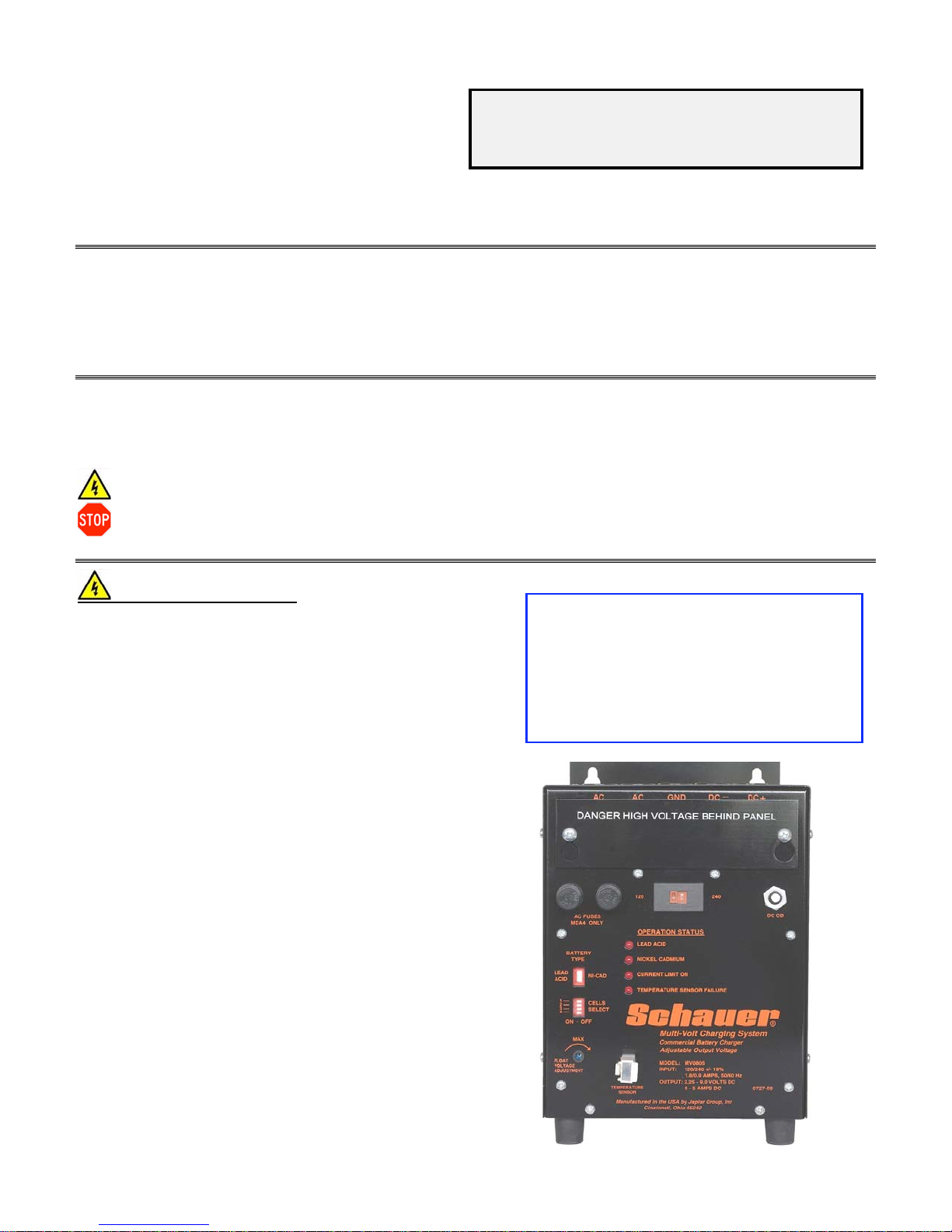
MODEL MV0805 BATTERY CHARGER
Schauer
PART NUMBER 0727-08
The enclosure for this model is powder
coat enamel painted steel. The mounting
bracket is made into the top of the rear
panel for permanent mounting. Electrical
connections are made through the cover
behind the electrical cover plate as
shown below and on page 2.

Instruction 1905072708 Rev A - 1 -
CHARGER THEORY OF OPERATION
This battery charger is powered by 120 or 240 volts AC, switch-selectable on the front panel. It is designed to
operate at 50 or 60 Hertz. The input circuit is protected with two 4 amp MDA type fuses. Surge suppression is
provided across the input terminals. The AC input provides voltage to the power transformer primary winding. The
transformer secondary provides an output voltage suitable for charging the batteries and is also electrically isolated
from the primary windings. The control board operates two high current SCR modules providing the AC to DC
rectification. The transformer output is filtered through a DC capacitor to provide a maximum of 500 millivolts AC
RMS at full rated output current. The filter capacitor is connected to a DC shunt that provides current sensing to the
control board for factory preset current limiting of the charger output. Although not recommended this output
current limit is customer adjustable. A Current Limit LED is located on the front panel to indicate a current limiting
condition.
The charger output is interrupted by a manual reset 20 amp circuit breaker providing over-current protection. The
batteries and wiring should be checked before resetting the circuit breaker if it trips. Surge suppression is provided
on the input and output terminals of the charger.
The battery charger is designed to operate as a constant current and constant voltage charger. When the
batteries are in a discharged state the control powers the SCRs to conduct in a constant current mode. As the
batteries become charged, the output current decreases. Once the battery voltage has reached the float voltage
setting the charger then performs as a constant voltage charger maintaining a float voltage that is customer-
adjustable within a limited range (see page 4 for adjustment range of each cell selection.
The control circuitry is designed to compensate charging voltage based on battery temperature changes with the
use of a temperature sensor plug (supplied) or an optional remote temperature sensor cable (12 or 25 ft.) attached
to the batteries for monitoring. This feature protects ONLY lead-acid batteries from over or under charging due to
temperature changes. An LED is located on the front panel to indicate improper operation of the temperature
compensation device. If no sensing device is connected or if the device is defective the TEMPERATURE SENSOR
FAILURE LED turns on. High and low voltage limits are designed into this circuit for extreme temperature
conditions.
Other set-up and operation controls (shown below) are selecting battery type, lead-acid or nickel-cadmium,
number of cells, float voltage adjustment and an LED for indication when the charger is operating in a Current
Limiting condition. Example, for an 8 VDC Lead-Acid system set the switch to Lead Acid and turn on cells 4.
Connections through the cover bushings to ” studs.
Charger set-up controls

Instruction 1905072708 Rev A - 1 -
Unpacking Battery Charger
Packed with each charger is a temperature sensor plug and two MOV assemblies. These may already be
installed when received. Inspect the charger for any damage during transit and report it immediately to the carrier.
DO NOT INSTALL THE CHARGER IF THERE IS EVIDENCE OF ANY SHIPMENT DAMAGE.
Battery Charger Installation
Location of the charger installation requires air flow for convection cooling of the equipment. There should be a
minimum space of 2” on the sides and 3” above the top of the charger for free air flow. Mounting keyhole brackets,
on a 5.25” centerline, are provided at the top of the charger rear panel. Proper gage wiring must be used to avoid
voltage drops across the DC wiring to the batteries.
DO NOT PLACE ANYTHING ON TOP OF THE CHARGER WHEN OPERATING. DAMAGE TO THE
CHARGER OR BATTERIES MAY OCCUR.
The two MOV assemblies are installed at the time of AC input power line connection. Connections are made to
the terminal board behind the electrical cover plate (see page 2 photo). The 320 volt MOV (longer lead wires) is
attached to the AC terminals of the input terminals. The 150 volt MOV (shorter lead wires) is attached to the
Ground terminal and the AC terminal next to it. Set the voltage selector switch on the front panel to the desired
input voltage (120 or 240). In either application the MOV installation remains the same. Connect the power source
wires to the AC input terminals making sure to provide a solid ground wire connected to the terminal marked GND.
The DC output portion of the charger should not be connected to batteries until all control switches and adjustments
have been made on the front panel. IF THE BATTERIES ARE CONNECTED AT THIS TIME A SPARK WILL
OCCUR DUE TO CHARGING OF THE FILTER CAPACITOR INSIDE THE CHARGER.
MAKE SURE ALL MOV AND INPUT POWER LINES ARE CONNECTED PROPERLY BEFORE
THE CHARGER IS ENERGIZED. CHARGER MUST BE SOLIDLY GROUNDED!
Battery Charger Control Set-up
1. Select the battery type Lead-Acid or Nickel-Cadmium.
2. Select the number of cells, 1 - 4 cells (ON to the left, OFF to the right).
3. Do not connect the temperature sensor plug or cable at this time.
4. Connect a digital DC Voltmeter to the charger DC output terminals.
5. Turn ON the AC main power supply to the charger.
6. After allowing the charger output voltage to stabilize, set the FLOAT VOLTAGE ADJUST potentiometer to the
desired float voltage. Recommended voltages at 77°F (25°C) are as follows;
Lead Acid Flooded = 2.20 volts/cell
Lead Acid Sealed = 2.25 volts/cell
Nickel Cadmium = 1.47 volts/cell all +/- .03 volts/cell
Always refer to the battery manufacturer’s recommendations for charging voltages.
7. Turn OFF the AC main power supply to the charger.
8. Connect the temperature sensor plug or cable to the front panel.
9. The batteries may now be connected to the DC output positive and negative terminals.
CAUTION: POLARITY OF THE DC CONNECTIONS MUST BE CORRECT.
Battery Charger Maintenance
The charger should be kept clean, dry and the electrical connections checked periodically for proper torque (30
inch/pounds). Surge suppressors (MOVs) should be inspected for damage to ensure continued protection. Verify
LEDs are functional. No other routine maintenance is required for this equipment.
Special Application
With the DC output being filtered through a high current electrolytic capacitor, there are also applications when
this charger can be used as a DC power supply. Contact the factory for further information.

Instruction 1905072708 Rev A - 1 -
Troubleshooting and Servicing
If the battery charger seems to be operating improperly begin with the basic steps below.
Symptom Possible Cause
No charger LED operation on the front panel Check AC input power supply line and charger fuses
Check for proper wiring at the connection terminal board
Charger LEDs operate but low or no DC output Verify proper DC connections and torque
Check DC circuit breaker and push to reset if required*
Charger in current limit – check batteries and cables
TEMPERATURE SENSOR FAILURE LED is ON Temperature sensor not connected or is defective
The charger stays in current limit at all times. Due to the size of the batteries in some applications it is
possible for the unit to remain in current limit for extended
periods of time. It depends on battery discharge level. Be
certain the charger is sized properly for the batteries used.
If the problem is not solved using the steps above bench testing is recommended rather than field
troubleshooting. Contact the factory for additional technical service. Please have the model number, part number
and date code (on base of charger) from the front panel information available prior to contacting the factory.
* The charger has a 20 amp DC circuit breaker. If it trips, be sure to check all wiring and the batteries before
resetting the circuit breaker.
Battery Charger Specifications
AC Input Voltage 120/240 VAC +/- 15%, 50/60 Hertz
AC Input Current 1.8/0.9 AAC +/- 5% @ 5 ADC Full Load
AC Input Regulation Range +/- 15% (102-138 @ 120 input, 204-276 @ 240 input)
AC Input Fuses 4 Amp MDA type only
Efficiency Rating 65 % @ 10.0 VDC, 5 ADC Output
No-Load Excitation Losses 8 Watts, 500 Milliamps @ 120 VAC 60 Hz Input
DC Output Voltage Range 1.30 – 10.0 VDC filtered output
DC Output Float Adjust Range Lead-Acid or NiCad +/- 10% of nominal setting
L/A Temperature Compensation Offset is 3mV per °F per cell when the sensor plug or cable is used
DC Output Current Limit 5.5 ADC +/- 3%
DC Output AC Ripple Less than 500 millivolts AC RMS @ 5 ADC at the DC output terminals
Physical Dimensions 7.125” Width x 9.0” Depth (including Temp Sensor) x 10.625” Height
Charger Weight 12.8 pounds
Approximate Output Voltage Per Cell Selection (at 1 ADC Output Load)
Battery Type Cells Minimum Adjustment Maximum Adjustment
Lead Acid 1 2.00 2.50
Lead Acid 2 4.02 5.02
Lead Acid 3 6.05 7.55
Lead Acid 4 8.07 10.08
Ni-Cad 1 1.30 1.62
Ni-Cad 2 2.61 3.27
Ni-Cad 3 3.94 4.92
Ni-Cad 4 5.25 6.57
These adjustment ranges may vary slightly from unit to unit due to resistor tolerances on the control board.

Instruction 1905072708 Rev A - 1 -
Replacement Parts List
Japlar Part Number Qty Req'd Description
4001026103 1 Power Transformer Assembly
3578V8 1 Electronic Control Board
0907000011 6 Control Board Mounting Stand-offs
651578 2 Front Panel Fuseholder
651323 2 AC Input Fuses 4 amp MDA type only
0505000044 1 DC Circuit Breaker 20 amp
3316010320 1 320 Volt AC MOV Assembly (longer lead wires) MOV1
3316010150 1 150 Volt AC MOV Assembly (shorter lead wires) MOV2
2076 1 DC Output MOV Assembly
3566-0 1 Temperature Sensor Plug
3308433508 1 Heatsink Assembly (including SCRs and wires)
3589 1 10 Amp 50 mV Current Shunt
600422 1 Output Filter Capacitor
619400 1 R1 Bleeder Resistor Assembly
3566-25 Optional 25 Feet Temperature Sensor Cable
3566-12 Optional 12 Feet Temperature Sensor Cable
Use only original equipment replacement parts in this battery charger as substitutions may have an adverse effect
on proper operation and reliability. Contact the
Japlar Group
sales department for parts orders.
For additional technical information contact the engineering department at 513-791-3030 extension 144.

Instruction 1905072708 Rev A - 1 -
Schematic for Reference
Table of contents
Other Schauer Batteries Charger manuals


